Note: Descriptions are shown in the official language in which they were submitted.
1 ~1 8 1 ~
-- 1
The present invention relates to a method for
transferring heat to molten metal contained in a reac-
tion vessel, and also to an apparatus which has a reac-
tion vessel and in which heat can be transferred to
molten metal contained in the reaction vessel. More
particularly, the invention relates to a method and an
apparatus wherein heat can be transferred to molten
metal contained in a reaction vessel in which CO gas
is generated and can be combusted.
Recently, various proposals have been made with
regard to a method for transferring heat to molten metal
contained in a reaction vessel, in which CO gas generat-
ed therein can be combusted.
Some converters are equipped with a lance, for
post-combustion, having nozzle holes in the lower end
thereof, through which oxygen gas is blown out. CO gas
generated from molten metal is post-combusted by oxygen
gas blown out through the nozzle holes, and the heat
produced thereby, as heat value necessary for the oper-
ation, is transferred through a layer of molten slagfloating on top of the molten metal.
In the above-mentioned conventional method, amount
of the CO gas generated is considerable, and the as-
~ cending speed thereof is, also, ~ast. As a result, the
time for performing heat exchange between the hightemperature post-combusted gas and foaming molten slag
is undesirably shortened. Thus, this results in the
1 3 1 ~ 1 3~
-- 2
efficiency in transferring heat to molten metal being
low.
Japanese Patent Application Laid Open No. 74390/82,
describes a method wherein:
(a) Fuel is supplied into a reaction vessel with
molten metal already therein;
(b) A gas jet stream is blown onto the surface of
the molten metal whereby the supplied fuel is gasified;
(c) The gasified gas is involved in the gas jet
stream gas and a part of the gasified gas is combusted;
and
(d) The gas generated by the combustion is con-
veyed, together with the heat produced by the gas com
bustion, onto the molten metal so as to transfer the
heat to thereto.
In the above-mentioned method, however, the gaseous
atmosphere above the molten slag is heated to a high
temperature by the combustion of carbon monoxide, but
the molten slag lies between the molten metal and the
heated gaseous atmosphere, and, in addition, contains
air. This produces the disadvantage in that the trans-
fer of heat to the molten metal is not as efficient as
it could be.
- An object of the present invention is to provide a
method for combusting optimizingly gas generated within a
reaction vessel, and for transferring the heat produced
thereby to molten metal contained in the vessel.
1 3 1 ~
-- 3 --
A further object of the present invention is to
provide an apparatus which has a reaction vessel and in
which gas generated within the vessel can be optimiz-
ingly combusted, and the heat produced thereby can be
effectively transferred to mo:Lten metal contained in the
vessel.
Another object of the present invention i5 to pro-
vide a method for decreasing the consumption of carbo-
naceous material used as the reducing agent.
These and other objects and advantages will become
more apparent from the following detailed description
of the invention, taken together with the accompanying
drawings.
According to the present invention, a method is
provided for transferring heat to molten metal contained
in a reaction vessel, which comprises the steps of:
supplying the molten metal into the vessel;
maintaining the pressure of the gaseous atmosphere
within the vessel higher than atmospheric pressure;
blowing in oxygen gas to the molten metal contained
in the vessel; and
blowing oxygen gas in the vessel, thereby to cause
post-combustion.
~ Further, according to the present invention, there
is provided an apparatus for transferring heat to molten
metal, which comprises:
a reaction vessel containing the molten metal;
1 3 1 ~ 1 3~
a regulator, connected with the vessel, for main-
taining and controlling the pressure of gaseous atmos-
phere higher than atmospheric pressure within the
vessel;
a first device for blowing oxygen gas to molten
metal contained in said react;;on vessel; and
at least one second device for blowing oxygen
gas in said reaction vessel, thereby to cause post-
combustion.
This invention can be more fully understood from
the following detailed description when taken in con-
junction with the accompanying drawings, in which:
Fig. 1 is a schematic view illustrating an appara-
tus embodying the present invention;
Fig, 2 is a schematic view illustrating another
example of an apparatus,embodying the present inven-
tion;
Fig. 3 is a schematic view of a further apparatus
embodying the present invention;
Fig. 4 is a schematic cross-sectional plan view
of an apparatus for blowing in oxygen gas for post-
combustion performed, according to the present inven-
tion;
~' Fig. 5 is a schematic sectional side elevation view
~5 of the apparatus shown in Fig. 4; and
Fig. 6 is a graphic representation showing the re-
lationship between oxygen flow-rate for post-combustion
1 3 1 ~
-- s
and heat efficiency.
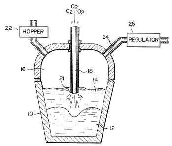
Referring now to Fig. 1 showing schematically an
apparatus having a smelting reduction furnace, wherein
an embodiment of a method according to the present
invention is carried out, reference numerals indicate
as follows:
10, furnace wall;
12, molten metal;
14, molten slag layer;
16, CO-CO2 gaseous atmosphere;
18, top-blow lance;
21, nozzle holes through which post-combustion
oxygen gas is blown out;
22, material feed hopper;
24, outlet opening to the gaseous atmosphere; and
26, pressure regulator for maintaining the pres-
sure of the gaseous atmosphere higher than
atmospheric pressure.
Iron ore and coal are charged through material
feed hopper 22, onto molten metal 12 within the vessel.
Oxygen gas is blown in through top blow lance 18. A
portion of the charged coal is combusted with the oxygen
gas blown in, and CO gas is produced. Another portion
~ dissolves into the molten metal, and the balance remains
in molten slag layer 14.
The iron ore is reduced by carbon contained in
molten metal 12 and molten slag layer 14. The CO gas
1 3 1 8 1 3~
-- 6
produced by the combustion process ascends through the
molten slag layer, and is further combusted with oxygen
gas blown out through noz~le holes 21 set in the lower
end of top blow lance 18, and heat is produces. The
combustion of the CO gas with the blown out oxygen gas
i5, throughout the description and the claims contained
herein, denoted by the term post-combustion. Amount of
oxygen gas for reduction and that of oxygen gas for
post-combustion are separately controlled.
CO-CO2 gaseous atmosphere 16 is kept at higher
than atmospheric pressure, by means of pressure regu-
lator 26 connected to outlet 24 which opens to the
gaseous atmosphere. Since keeping the pressure higher
than atmospheric pressure is maintained, the slower
the post-combusted gas ascends, the longer the post-
combusted gas stays in molten slag layer 14. In ad-
dition, there is a greater chance that the CO gas
ascending through the molten slag layer will mix with
oxygen gas provided for the post-combustion, and will
be combusted therewith.
Thus the decrease of the speed at which the gas
ascends through the molten slag layer lengthens the
time for heat exchange to take place, and, as a result,
improves the heat transfer to the molten slag layer.
Finally, the heat transfer to the molten metal is at-
tained through the molten slag layer. This results in
effective use of thermal energy~
1 ~1 81 3~
-- 7 --
In the foregoing, the embodiment according to the
present invention is applied to a smelting reduction pro-
cess for iron ore. The application thereof, however,
is not limited to the smelting reduction process and can
be applied to steel making for decarburi2ation and de-
phosphorization.
To carry out the embodiment, it is preferable to
keep the pressure of gaseous atmosphere 16 at approxi-
mately 2 to 5 kg/cm2. This range reduces the speed at
which the post-combusted gas ascends, to a half to a
fifth of the conventional rate and also lowers the rate
of ascend of the CO gas generated in the molten metal.
This pressure range does not affect the speed of the
reaction represented by the following formula:
C + -~-2 = CO
If the pressure is less than 2 kgfcm2, it may be
impossible to reduce the rate of ascend of the post-
combusted CO2 gas and the generated CO gas.
On the other hand, a pressure of more than 5 kg/cm2
may undesirably reduce the speed of the reaction, which
is given by the above-mentioned formula. The pressure
of CO-CO2 gaseous atmosphere 16 is controlled by pressure
- regulator 26, more precisely by controlling the opening
of the valve of regulator 26 in accordance with the
pressure measured.
In this embodiment, oxygen gas for post-combustion
- 8 -
is blown in through nozzle holes 21 set in the lower end
of lance 18. Alternatively, the oxygen gas can be blown
in other ways.
Fig. 2 schematically illustrates an example of
another apparatus according to the invention having a
reaction vessel provided with a plurality of side-blow
tuyer0s 20 set in wall 10. Through tuyeres 20, oxygen
gas for post-combustion can be blown into the molten
metal layer. These ~uyeres 20 are sloping downward and
open to the layer of slag contained in the vessel The
quantity of charging material and the quantity of
tapping molten metal are controlled so as to keep the
level of layer 14 constant. Material is charged through
feeding hopper 22. A tapping hole for the molten metal
(not shown) can be cut in the furnace wall in the pub-
licly known manner.
Oxygen gas, for reduction, is blown in molten metal
12, through top blow lance 18. The oxygen gas for post-
combustion is blown into the vessel through tuyeres 20
sloping downward and opening to layer 14 of molten slag.
As a result, the molten slag first moves downward, then
hits against the top of the molten metal, and finally
moves upward, thus circulating within the vessel. The
- oxygen gas reacts with CO gas ascending through layer 14
of molten slag. The reaction heat is transferred to the
molten slag, and is further to molten metal 12, since
the molten s:Lag is circulating.
1 3 ~
Tuyerss 20 are sloping downwards in the apparatus
shown in Fig. 2. They can be inclined upward, in which
case the molten slag can circulate in the same manner.
However, it is preferable that tuyeres 20 be sloping
downwards, since more oxygen gas can be blown into the
molten slag, and the molten slag can circulate more
vigorously.
Furthermore, in place of top-blow lance 1~ shown in
Fig. 2, for blowing in oxygen gas for reduction, bottom-
blow tuyeres 19 shown in Fig. 3 can be employed.
Figs. 4 and 5 show still another apparatus havinga reaction vessel. A plurality of bottom-blow tuyeres
19 are set in the bottom of the vessel, and a plurality
of side-blow tuyeres 20 are provided in furnace wall
10 of the vessel. Side-blow tuyeres 20 are inclined,
in a horizontal plane, at angle ~ to the radius of the
vessel, as is shown in Fig. 4. Some of tuyeres 20 are
sloping downwards, and the others are sloping upwards,
as is illustrated in Fig. 5. Angle ~ can be given as
follows:
0 < ~ < 180/n, where n is the number of tuyeres 20
and is 3 or more, or
0 ~ ~ 45, where n = 2.
- Angle 9 can be changed within the ranges repre-
sented by the foregoing formulas. If angle ~ falls
outside the ranges, the molten slag cannot circulate
sufficiently.
1 3 1 8 1 3~
-- 10 --
In the apparatus of Figs. 4 and 5, all tuyeres 20
are inclined at the same angle to the radius of the
vessel. Instead, some of tuyeres 20 can be inclined at
an angle, whereas the others can be inclined at another
angle.
As has been described, some of tuyeres 20 are
sloping downwards, and the others are sloping upwards.
More specifically, they can be sloping alternately down-
wards and upwards, or, for instance, any two adjacent
tuyeres 20 can be sloping down while the next two are
sloping up.
Side-blow tuyeres 20 are set in furnace wall 10
such that they open to layer 14 of molten slag. Molten
metal 12 is kept moving by the stream of oxygen gas
provided for the reduction thereof, or by the blow
of powders and gas blown thereon during the smelting
reduction process, but the surface level of the molten
metal and the thickness of the molten-slag layer are
constantly controlled. Accordingly, the side-blow
tuyeres can be positioned to open to the molten-slag
layer.
Oxygen gas for reduction is blown in through outer
pipe 25 of bottom-blow tuyeres 19, and fine iron ore and
- powdered coal are blown in through inner pipe 23 of
tuyeres l9. Oxygen gas for post-combustion is blown in
through side-blow tuyeres 20. Layer 14 of molten slag
highly heated by post-combustion is circulated within
1 31 81 3~
the vessel, in both a horizontal plane and a vertical
plane, and transfers the heat to molten metal 12 since
it contacts metal 12.
Example 1
An example of smelting reduction of iron ore will
now be described, using the apparatus shown in Fig. 1,
according to the present invention.
In this example, 50 tons of molten metal 12 was fed
into the melting reduction furnace. The pressure of
gaseous atmosphere 16 was set to 3 kg/cm2 by pressure
regulator 26.
Iron ore and coal were fed through feeding hopper
22. Oxygen gas for reduction was blown in through lance
18, and oxygen gas for post-combustion was blown in
through nozzle holes 21 set in the lower end of the
lance.
The oxygen gas for post-combustion was introduced
into molten slag layer 14 in an amount of 50% of oxygen
flow-rate for post-combustion which is given as follows:
oxygen flow-rate amount of 2 for post-combustion
for post-combustion = amount of CO qenerated
( % ) c ~ ~ ~
x 100
- Rate of molten metal production was 32 tons/hour.
To demonstrate the advantage of the inven-tion,
Controller 1, wherein gaseous atmosphere 16 was set to
atmospheric pressure, was carried out, thereby producing
, 13l~l3l~
- 12 -
molten metal at the rate of 32 tons/hour. The results
are shown in Table 1, along with the results of
Example 1.
Table 1
.. , _ _
Controller 1 Example 1
.. _ . ., . _ .
Iron ore (kg/min.) 840 840
. . .~ .___ .
Coal (kg/min.) 380 312
_. ~ ~
Amount of 2 (Nm3/min.) 275 225
. _._ , . _ . _ . _ _
Oxygen flow-rate for 47 48
p_st-combustion (%)_ _ _ _ _
Heat efficiency (~) 63 80
_
The "heat efficiency" is given:
Heat efficiency = AB
where A represents heat given to molten metal, and B
represents heat produced`when all oxygen gas for post-
combustion is consumed.
In Example 1, as is clearly understood from Table 1,
the consumption of coal and that of oxygen gas were
reduced, compared with Controller 1, since the heat
efficiency of Example 1 was higher than that of
Controller 1.
Example 2
Another example of smelting reduction of iron ore
was carried out, using the apparatus shown in Fig. 1.
The smelting operation was performed with gaseous
1 ~ 1 8 1 ;~
- 13 -
atmosphere 16 being set at a pressure of 3 kg/cm2, and
oxygen gas for post-combustion was introduced in oxygen
flow-rate for post-combustion of 0 to 100%.
Controller 2, wherein gaseous atmosphere 16 was set
to atmospheric pressure, and oxygen gas was introduced
in the same oxygen flow-rate for post-combustion was
performed.
Fig. 6 shows graphically the results of Example 2
and Controller 2. The results of Example 2 and Con-
troller 2 are illustrated respectively by a solid and a
broken line. As these lines show, the heat efficiency
of Example 2 is 15~, on average, higher than that of
Controller 2. Therefore, the transfer of heat to the
molten metal can be achieved efficiently by controlling,
appropriately~ the pressure of gaseous atmosphere 16,
by means of pressure regulator 26 in compliance with the
amount of CO gas generated and with the state of foaming
molten slag layer 14.
Example 3
In this example, two different test operations of
smelting reduction were carried out by changing the
method of blowing in oxygen gas for post-combustion.
The pressure of gaseous atmosphere 16 was set to
~ 3 kg/cm2.
Test oDeration A
..
An apparatus as is shown in Fig. 2 was employ-
ed. Oxygen gas for reduction, and oxygen gas fox
- l4 -
post-combustion, were respectively blown in straight
downwards through lance 18 and at a downward-sloping
angle through six side-blow tuyeres 20.
Test operation B
An apparatus as is shown in Figs. 4 and 5 was em-
ployed. Six side-blow tuyeres 20 were set in furnace
wall 10 at angle ~ of 30~. Three bottom-blow tuyeres
19 were each composed of an inner pipe 23 and an outer
pipe 25 embracing inner pipe 23. Oxygen gas for reduc-
tion, was introduced through outer pipe 25 of each
tuyere 19, and a mïxture of fine iron ore and powdered
coal, was introduced through inner pipe 23. Oxygen gas
for post-combustion was blown in through side-blow
tuyeres 20, so as to circulate the molten slag in both
a horizontal plane and a vertical plane.
The results of the operations A and B are listed,
together with those of Example 1, in Table 2.
1 3 1 8 1 3~
- 15 -
Table 2
. , , _ _
Example 1 Example 3A Example 3B
. . _ _ . . ... _
(kg/min.) 840 840 840
(kg/min.) 312 305 298
._ ~
Amount of 2
(Nm3/min.) 225 220 215
Oxygen flow-rat~ _ __ _ _
for post-combus- 48 49 48
tion (%)
.. _
Heat efficiency 80 86
The results of Examples 3A and 3B proved an im-
provement in the heat efficiency, and a reduction in the
consumption of coal and oxygen needed for reduction, in
comparison ~ith Example 1.