Language selection

Search

Patent 1318163 Summary

Third-party information liability

Some of the information on this Web page has been provided by external sources. The Government of Canada is not responsible for the accuracy, reliability or currency of the information supplied by external sources. Users wishing to rely upon this information should consult directly with the source of the information. Content provided by external sources is not subject to official languages, privacy and accessibility requirements.

Claims and Abstract availability

Any discrepancies in the text and image of the Claims and Abstract are due to differing posting times. Text of the Claims and Abstract are posted:

  • At the time the application is open to public inspection;
  • At the time of issue of the patent (grant).
(12) Patent: (11) CA 1318163
(21) Application Number: 609193
(54) English Title: FENCE DROPPER
(54) French Title: RENFORT DE CLOTURE
Status: Deemed expired
Bibliographic Data
(52) Canadian Patent Classification (CPC):
  • 91/9
(51) International Patent Classification (IPC):
  • E04H 17/02 (2006.01)
  • E04H 17/10 (2006.01)
(72) Inventors :
  • RAYNER, ERNEST (Australia)
(73) Owners :
  • RAYNER, ERNEST (Australia)
(71) Applicants :
(74) Agent: BERESKIN & PARR
(74) Associate agent:
(45) Issued: 1993-05-25
(22) Filed Date: 1989-08-23
Availability of licence: N/A
(25) Language of filing: English

Patent Cooperation Treaty (PCT): No

(30) Application Priority Data:
Application No. Country/Territory Date
PJ0064 Australia 1988-08-26

Abstracts

English Abstract


ABSTRACT
"FENCE DROPPER"

A fence dropper formed from a length of rod or wire
bent to a central generally linear portion having arms
extending at right angles from either end of the central
portion is provided with loops at either end of the central
portion and one or more intermediate loops between the loops
at either end. Each loop is designed to engage a parallel
fence wire when the arm portions are at right angles to the
fence wires, and to restrain the fence wire within an
aperture defined by the loops when the arms are rotated to
lie alongside the top and bottom end wires. Provision is
made to engage the free ends of the arms with the fence
wires when in the parallel configuration.


Claims

Note: Claims are shown in the official language in which they were submitted.

- 6 -

THE EMBODIMENTS OF THE INVENTION IN WHICH AN EXCLUSIVE
PROPERTY OR PRIVILEGE IS CLAIMED ARE DEFINED AS FOLLOWS:
1. A fence dropper formed by bending a length of rod
and adapted to engage at least the top and bottom wires of a
multi-strand wire fence, said fence dropper comprising a
central generally linear portion having loops formed at
either end and arm portions extending from the loops
parallel to one another laterally of the central portion and
terminating at their free ends in wire engagement means,
the loops being shaped to engage the top and bottom wires by
longitudinal movement of the dropper laterally relative to
each wire with the arms orientated at right angles to the
wires, and to provide vertical restraint for each wire when
the central portion of the dropper is rotated about its own
axis until the arms are substantially parallel to the wires.

2. A fence dropper as claimed in claim 1 wherein the
wire engagement means comprise a U-bend at the free end of
each arm, each U-bend having a nose portion and an open end
opening laterally of the respective arm portion and
orientated such that the nose portion leads when the central
portion of the dropper is rotated about its own axis to
engage the top and bottom wires.

3. A fence dropper as claimed in claim 2 wherein the
U-bends are narrowed or necked adjacent their open ends so
that they may be clipped in place over the top and bottom
wires of the fence.

4. A fence dropper as claimed in claim 1 wherein
additional loops similar in configuration to the loops
formed at either end of the central portion are formed at
intermediate locations in the central portion adapted to
support the intermediate wires of a multi-strand fence.

- 7 -
5. A fence dropper as claimed in claim 1 wherein each
said loop comprises interconnected first and second portions
each being bent through an angle greater than 180° and
defining a necked aperture between the first portion and the
adjacent central portion, the neck of each aperture being
sized and orientated such that a fence wire may pass through
the neck into the aperture when the arms are orientated at
right angles to the wires, but so that a fence wire may not
pass through the aperture when the arms are located
generally parallel to the fence wires.

Description

Note: Descriptions are shown in the official language in which they were submitted.


- 2 - 1 3~ 3

~FENCE DROPPER~
This invention relates to a fence dropper devised
particularly to engage and separate the parallel wires of a
multi-strand wire fence.
BACKGROVND OF THE INVENTION
It is well known to provide fence droppers of various
types to separate and support the various strands of a
multi-strand wire fence. Early examples of fence droppers
comprised timber battens into which were nailed a number of
staples each engaged with one strand of the fence. Droppers
of this nature were expensive both to manufacture and to
install and were generally replaced by metal rod or wire
type fence droppers of the type described in Australian
Patent Specification 402869. Fence droppers of the type
described in that patent have a central rod portion with
transverse arms at either end shaped so that the top and
bottom wires of the fence can be engaged with the dropper by
entwining the wires about the lateral arms. Loops are
provided in the intermediate sections of the central portion
adapted to engage and support the intermediate wires of the
fence. Fence droppers of this type have the disadvantage
that tightly strained upper and lower wires in a fence are
often difficult to entwine about the lateral arms requiring
the use of a tool such as a screwdriver to wind the arms
onto the top and bottom wires. This procedure is awkward
and time consuming, and can damage the wires.
SUMMARY OF THE INVENTION
The present invention therefore provides a fence
dropper formed by bending a length of rod and adapted to
engage at least the top and bottom wires of a multi-strand
wire fence, said fence dropper comprising a-central
generally linear portion having loops formed at either end
and arm portions extending from the loops parallel to one
another laterally of the central portion and terminating at
their free ends in wire engagement means; the loops being
shaped to engage the top and bottom wires by longitudinal
movement of the dropper laterally relative to each wire with
the arms orientated at right angles to the wires, and to
024ls/rs

_ 3 _ ~31o~3

provide vertical restraint for each wire when the central
portion of the dropper is rotated about its own a~;s until
the arms are substantially parallel to the wires.
Preferably additional loops similar in configuration to
the loops formed at either end of the central portion are
formed at intermediate locations in the central portion
adapted to support the intermediate wires of a multi-strand
fence.
Preferably the wire engagement means comprise a U-bend
at the free end of each arm, each U-bend having a nose
portion and an open end opening laterally of the respective
arm portion and orientated such that the nose portion leads
when the central portion of ths dropper is rotated about its
own axis to engage the top and bottom wires.
Preferably the U-bends are narrowed or necked adjacent
their open ends so that they may be clipped in place over
the top and bottom wires of the fence.
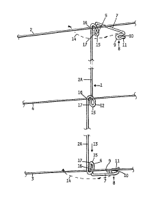
~DESCRIPTION OF THE DRAWINGS
Notwithstanding any other forms that may fall within
its scope, one preferred form of the invention will now be
described by way of example only with reference to the
accompanying drawings in which:
Fig. 1 is an elevation of a portion of a three wire
multi-strand fence showing a ence dropper according to the
invention slideably engaged with the fence wires,
Fig. 2 is a similar view to Fig. 1 showing the fence
dropper rotated through 90 with the arms parallel to the
fence wires, and
Fig. 3 is a similar view to Fig. 2 showing the U-b0nds
at the end of the arms engaged with the top and bottom fence
wires.
DESCRIPTIO~ OF THE PREFERRED ~MBODIMENT
In the preferred ~orm of the invention a fence dropper
1 is formed by bending a length of wire or rod to a shape
that is adaptsd to engage at least the top wire 2 and the
bottom wire 3 of a multi-strand wire fence and preferably
also any intermediate wires typically shown at 4. The fence
dropper comprises a central portion 2A having loops 5 and 6
024ls/rs

~ ~3 ~ 8 ~


formed at either end. The rod forming the fence dropper
e~tends outwardly from the loops in arm portions 7 formed
parallel to one another and laterally of the central portion
2A and terminating at their free ends inwire engagement
means. The engagement means may simply comprise a
downturned portion at the end of the top arm and an upturned
portion at the end of the bottom arm, but in the preferred
form of the invention they comprise U-bends 8 each having a
nose portion 9 and an open end 10 opening laterally of the
arm portions 7. In the preferred form of the invention the
U-bends are further provided with a necked or re-entrant
portion 11 arranged to provide a spring clip action over the
top and bottom wires 2 and 3 as will be described further
below.
The dropper may also be provided with one or more
intermediate loops 12 located in positions on the central
portion 2A correspondin~ to the location of intermediate
fence wires 4.
The loops 5 and 12 are shaped to slideably engage the
fence wires by longitudinal movement of the dropper
laterally across the wires with the arms orientated at right
angles to the wires as shown in Fig. 1. The longitudinal
movement of the dropper is indicated by arrow 13. The lower
wire 3 is then raised and dropped laterally into the lower
loop 6.
The loops are shaped as shown in the drawings so that
when the fence dropper is engaged with the fence wires in
this manner, the dropper may be rotated axially about its
central portion as shown by arrows 14 to bring th~ arms
parallel with the top and bottom wires 2 and 3 as shown in
Fig. 2. The shape of the loops 5, 6 and 1~ are such that
when the dropper is rotated in this manner, the loops
effectively lock around the fence wires preventing either
upward or downward movement of the wires relative to the
dropper. To this end each loop comprises a first portion 15
~ent through greater than 180 and defining a necked
aperture 16 between the first portion and the adjacent
central portion 2A. The wire is shaped to orm a re-entrant
024ls/rs

_ 5 _ ~3~3;~ 3

neck 17 to each aperture 16. It is into this aparture that
the fence wire is engaged with the dropper in the position
shown in Fig. 1, i.e. with the arms 7 at right angles to the
fence wires. When the dropper is rotated about the axis of
its central portion, rotation o the plane of the loops 15
causes the neck 17 of each aperture 16 to close below wires
2 and 4 and above wire 3, effectively restraining the wires
within the apertures 16. Once the fence dropper has been
rotated into this position the U-bends 8 at the ends of the
arms 7 may be engaged with the top and bottom wires 2 and 3
as shown in Fig. 3 by reversing the rotation of the dropper
and entering the top and bottom wires into the open ends 10
of the U-bends. Due to the necked nature of the U-bends as
shown at 11, the wires can be clipped in place within the
U-bends securely locating and engaging the top and bottom
wires in the U-bends and locking the dropper securely into
place on the fence wires.
In this manner a fence dropper is provided which is
both inexpensive and simple to manufacture and which
furthermore is quick and sim-ple to engage with the wires of
a fence without the use of any e~ternal tools. By the
nature of the dropper, its engagement with the fence wires
does not require any deformation of the wires or any
twisting about the arms of the dropper and therefore the use
of fence droppers of this type according to the invention
does not result in any damage to the wires of the fence.


024ls/rs

Representative Drawing
A single figure which represents the drawing illustrating the invention.
Administrative Status

For a clearer understanding of the status of the application/patent presented on this page, the site Disclaimer , as well as the definitions for Patent , Administrative Status , Maintenance Fee  and Payment History  should be consulted.

Administrative Status

Title Date
Forecasted Issue Date 1993-05-25
(22) Filed 1989-08-23
(45) Issued 1993-05-25
Deemed Expired 2003-05-26

Abandonment History

There is no abandonment history.

Payment History

Fee Type Anniversary Year Due Date Amount Paid Paid Date
Application Fee $0.00 1989-08-23
Maintenance Fee - Patent - Old Act 2 1995-05-25 $50.00 1995-05-11
Maintenance Fee - Patent - Old Act 3 1996-05-27 $50.00 1996-05-23
Maintenance Fee - Patent - Old Act 4 1997-05-26 $50.00 1997-05-20
Maintenance Fee - Patent - Old Act 5 1998-05-25 $350.00 1998-06-04
Maintenance Fee - Patent - Old Act 6 1999-05-25 $150.00 1999-05-21
Maintenance Fee - Patent - Old Act 7 2000-05-25 $150.00 2000-05-19
Maintenance Fee - Patent - Old Act 8 2001-05-25 $150.00 2001-04-20
Owners on Record

Note: Records showing the ownership history in alphabetical order.

Current Owners on Record
RAYNER, ERNEST
Past Owners on Record
None
Past Owners that do not appear in the "Owners on Record" listing will appear in other documentation within the application.
Documents

To view selected files, please enter reCAPTCHA code :


To view images, click a link in the Document Description column. To download the documents, select one or more checkboxes in the first column and then click the "Download Selected in PDF format (Zip Archive)" or the "Download Selected as Single PDF" button.

List of published and non-published patent-specific documents on the CPD .

If you have any difficulty accessing content, you can call the Client Service Centre at 1-866-997-1936 or send them an e-mail at CIPO Client Service Centre.


Document
Description 
Date
(yyyy-mm-dd) 
Number of pages   Size of Image (KB) 
Prosecution Correspondence 1992-08-05 2 71
Prosecution Correspondence 1991-09-19 1 34
Examiner Requisition 1992-02-07 1 67
Examiner Requisition 1991-05-23 1 32
PCT Correspondence 1993-03-01 2 80
PCT Correspondence 1989-09-06 1 38
Representative Drawing 2002-02-18 1 6
Description 1993-11-16 4 194
Drawings 1993-11-16 2 38
Claims 1993-11-16 2 58
Abstract 1993-11-16 1 19
Cover Page 1993-11-16 1 12
Fees 1998-06-04 1 32
Fees 1997-05-20 1 79
Fees 1996-05-23 1 40
Fees 1995-05-11 1 42