Note: Descriptions are shown in the official language in which they were submitted.
~ 3 ~
SULFUR SORBENT FEED SYSTEM FOR A FLUIDIZED BED REACTOR
3ack~round of the Invention
This invention relates to a fluidized bed reactor in
which heat is generated by the combustion of fuel in a
fluidized bed, and, more particularly, to a sulfur sorbent
feed system for the reactor.
~ Fluidized be~ reactors, combustors, or gasifiers, are
: well known. In these arrangements, air is passed through
a bed of particulate material, including a fossil fuel
such as coal and an adsorbent for the sulfur generated as
a result of combustion of the coal, to fluidize the bed
and to promote the combustion of the fuel at a relatively
: low temperature. When the heat produced by the fluidized
bed is utilized to convert water to stearn, such as in a
st:eam generator, the fluidized bed system offers an
attractive combination of high heat release, high sulfur
adsorption, low nitrogen oxides emissions and fuel
flexibility.
The most typical fluidized bed combustion system is
commonly referred to as a bubbling fluidized bed in which
a bed of particulate materials is supported by an air
distribution plate, to which combustion-supporting air is
introduced through a plurality of perforations in the
plate, causing the material to expand and take on a
suspended, or fluidized, s~ate. In the vent the reactor
is in the form of a steam generator, the walls of the
reactor are formed by a plurality of heat transfer tubes.
The heat produced by combustion within the fluidized bed
is transferred to a heat exchange medium, such as water,
circulating through the tubes. The heat transfer tubes
are usually connected to a natural water circulation
circuitry, including a steam drum, for separating water
from the steam thus formed which is routed to a turbine to
generate electricity or to a steam user.
In an effort to extend the improvements in combustion
efficiency, pollutant emissions control, and operation
turn-down afforded by the bubbling bed, a fluidized bed
reactor has been developed utilizing a fast, or
circulating, fluldized bed. ~ccording to this technique,
higher fluidized bed densities are attained which is well
below those of a typical bubbling fluidized bed. The
formation of the low density circulating fluidized bed is
due to its small particle size and to a high solids
~3~ ~8l~
throughput, which requires high solids recycle. The
velocity range of a circulating fluidized bed is between
the solids terminal, or free fall, velocity and a velocity
which is a function of the throughput, beyond which the
bed would be converted into a pneumatic transport line.
Although the circulating fluidized bed enjoys several
operational advantages when compared to the bubbling
; fluidized bed it is not without problPms. For example,
the sorbent material introduced into the bed is usually of
only one partlcle size. This limits fuel flexibility and
causes excessive flyash and bed chemistry problems
resulting in sintering and agglomeration. Also, the use
of sorbent material of the same particle size causes
relatively slow start-ups and load change capability since
the solids inventory and the furnace combustor cannot he
adjusted rapidly as demanded by the operational
requirement~.
Summary of the Invention
It is, therefore, an object of the present invention
to provide a sorbent injection system for a fluidized bed
reactor which enables sorbent of varying particle sizes to
be introduced into the reactor.
It is a further object of the present invention to
provide a sorbent feed system of the above type which
permits a greater variety of fuels to be used.
g 4
It is a further object of the present invention to
provide a system of the above type which minimizes the
amount of flyash produced in the reactor.
It is a further object of the present to provide a
sorbent feed system of the above type in which the ratio
of absorbent between the Ded and the upper
furnace~combustor can be varied to improve operational
characteristics.
It is a further object of the present invention to
provide a sorbent feed system of the above type which
permits faster start-ups and load changes.
It is a further object of the present invention to
provide a sorbent feed system of the above type in which ~'
;~ bed chemistry problems are avoided by offsetting the
chemical balance in the bed.
It is a further object of the present invention to
provide a system of the above type in which the solids
inventory in the furnace combustor can be adjusted rapidly
.
as demanded by the operational requirements.
Toward the fulfilIment of these and other objects the
system of the present invention comprises a reactor
containing a bed of solid particulate fuel material and
sulfur sorbent material. Air is introduced into the bed
at a velocity sufficient to fluidize the particulate
material and support the combustion of the fuel. A
~ 31~4
separating section is provided for receiving a mixture of the air, the
gaseous products oE combustion~ and the particulate material entrained
thereby. The separating section separates the particulate material from
the mixture and the separated particulate material i9 returned back to
the bed. Relatively coarse sorbent and relatively flne sorbent material
are introduced into said combustor at two separate locations.
In view of the above, it may be seen that the current invention
provides a fluidi~ed bed reactor of the type having a furnace section, a
bed of solid particulate material including fuel supported in the furnace
section, means for introducing air into the bed at a velocity sufficient
to fluidi~e the particulate material and support the combu~tion of the
fuel, and a separating section. A mixture is created of the air, gaseous
products of the combustion, and the particulate material entrained by the
air and gaseous products of combustion. The mixture is directed to the
separating section, where the particulate material is separated from the
mixture. Means are provided that connect the separating section to the
furnace or returning the separated particulate material back to the
bed~ First and second supply sources respectively supply relatively
coarse sorbent material and relatively fine sorbent material. The
~0 relatively coarse and relatively fine sorbent material are introduced
directly from the first and second supply sources into the furnace
section at two separate locations, respectively. Means also are provided
Eor introducing the relatively coarse sorbent material and the relatively
fine sorbent material directly from the first and second supply sources
to the connecting means that connect the separating section to the
furnace section.
8ll
~ 5a -
_~e~ gs.ription of the Draw~ngs
The above brief description, as well as further objects, features and
advantages of the present invention will be more fully appreciated by
reference to the following detailed description of the presently
preferred, but nonetheless, illustrative embodiments in accordance with
the present invention when taken in conjunction with the accomparlying
drawings wherein:
FIG. 1 is a schematic front view of a fluidized bed reactor; and
FIGS. 2 ~ 3 are schematic plan view~ of two embodiments of the
sorbent injecting ~ystem of the present invention utilized in connection
with the`reactor of FIG. 1.
Description of the Preferred Embodiment
Referring to FIG. 1 of the drawings, the reference numeral 8 refer6
in general to a fluidized bed reactor, in
,.,~,~
, . c_~
L~
the form of a steam generator, which includes a furnace
section 10, a separator 12 and a heat recovery area 14.
An air distributor, or grate, 15 is provided in the lower
portion of the furnace section 10 for reasons that will be
described. The separator 12 is in the form of a cyclone
separator which receives a mixture of air and the products
of combustion from the furnace section 10 along with the
solid particles entrained thereby. The separator 12
operates to separate the solids from the gases, and the
latter are passed to the heat r~covery area 14. The
solids from the separator 10 fall down into a hopper
section 12a of the separator where they are reinjected,
via a recycle conduit 16, to the lower portion of the
furnace section 10. The gases, after passing through the
heat recovery area 14 exit therefrom via an outlet conduit
14a. Since the above mentioned components and techniques
are conventional, they will not be described in any
further detail.
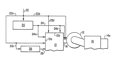
FIG. 2 depicts the components of FIG. 1 shown in
connection with the sorbent feed system of the present
invention. The sorbent feed system includes a pulverizer
20 which receives sorbent from an inlet pipe 22 which is
connected to a source of the sorbent. The crushed sorbent
from the pulverizer 20 is fed, via a conduit 24, to the
recycle conduit 16.
:~31~
A pair of branch conduits 24a and 24b are connected
to the condui~ 24 and, in turn, introducP the sorbent to
the furnace section 10, via a front wall lOa and a side
wall lOb preferably at the lower portion of the furnace
section. The inlet supply conduit 2Z branches into two
conduits 22a and 22b, with the conduit 22a extending to
the front wall lOa o the furnace section 10 and tha
conduit 22b extending to the recycle conduit 16. A branch
conduit 22c extends from the conduit 22a to a coal crusher
26. The sorbent from the branch c:ondui~ 22c is combined
with the coal in the crusher 26 and the mixture introduced
into the furnace section 10 via a conduit 28 and the wall
lOa.
A branch conduit 22d extends from the conduit 22b to
the wall lOb of the furnace section 10 for introducing the
relatively coarse sorbent into the fluidized bed in the
furnace section. Thus, a relatively coarse material is
introduced, via the branch conduit 22a into the furnace
section 10 and, via the conduit 22b, into the recycle
conduit 16. Also, relativ~ly coarse material is passed,
via the branch conduit 22a and the branch conduit 22c into
the coal crusher 26 where it is combined with the fuel
material in the crusher 26 and is passed, via the conduit
28, into the furnace section 10. Sorbent of a relatively
small particle size from the pulverizer 20 is introduced,
i 3 ~
via the conduit 24, into the recycle conduit 16, and, via
the branch conduits 24a and 24~, into ~he furnace section
10 via the walls lOa and lOb, respectively.
The embodiment of FIG. 3 is similar to that of FIG. 1
but utilizes separate sources of relatively fine sorbent
and coarse sorbent which are introduced, via conduits 30
and 32, to the furnace section 10 via the wall lOc, and to
the recycle conduit 16, respectively. A branch conduit
30a extends from the conduit 30 and to the recycle conduit
16, while a branch conduit 30b extends from the conduit
30a to the furnace section 10, via the wall lOc. Also,
branch conduits 32a and 32b extend from the conduit 32
into the furnace section 10 via the walls lOa and lOb.
It is understood t~at the sorbent material, although
generally coarse or fine in accordance with the foregoing,
may have a size distribution within a desirable range.
Also, it is understood that the crusher/pulverizer 20 of
the embodiment o~ FIG. 2 can be adapted to vary the size
distribution within a desirable range which can be
accomplished either on or off-line adjustment to the
operation of the crusher pulverizer.
It is also understood that long term storage silos
and day bins may be provided for the storage of the
sorbent material, and the feed system discussed above may
13 l~
either be gravity, pneumatic or chemical or a combination
of two or more of these techniques.
The sorbent injection system of the present invention
has several advantages. For example, it enables sorbent
of varying particle sizes to be introduced into the
reactor and a greater variety of fuels to be used. Also,
it minimizes the amount of flyash produced in the reactor
and enables the ratio of absorbent between the bed and the
upper furnace/combustor to be varied to improve
operational characteristics. Further, it permits faster
start-ups and load changes, and avoids chemistry problems
by offsetting the chemical balance in the bed. Finally,
it enables the solids inventory in the furnace combustor
to be adjusted rapidly as demanded by the operational
requirements.
A latitude of modification, change and substitution
is intended in the foregoing disclosur~ and in some
instances some features of the invention will be employed
without a corresponding use of other features.
Accordingly, it is appropriate that the appended claims be
construed broadly and in a manner consistent with the
scope of the invention.