Language selection

Search

Patent 1318640 Summary

Third-party information liability

Some of the information on this Web page has been provided by external sources. The Government of Canada is not responsible for the accuracy, reliability or currency of the information supplied by external sources. Users wishing to rely upon this information should consult directly with the source of the information. Content provided by external sources is not subject to official languages, privacy and accessibility requirements.

Claims and Abstract availability

Any discrepancies in the text and image of the Claims and Abstract are due to differing posting times. Text of the Claims and Abstract are posted:

  • At the time the application is open to public inspection;
  • At the time of issue of the patent (grant).
(12) Patent: (11) CA 1318640
(21) Application Number: 1318640
(54) English Title: TEMPORARY CLOSURE FOR USE WITH STORAGE TANKS
(54) French Title: DISPOSITIF DE FERMETURE TEMPORAIRE POUR RESERVOIRS
Status: Term Expired - Post Grant
Bibliographic Data
(51) International Patent Classification (IPC):
  • B65D 39/00 (2006.01)
  • B65D 39/08 (2006.01)
(72) Inventors :
  • FERNANDES, ELSON G. (Canada)
(73) Owners :
  • CLEMMER INDUSTRIES LIMITED
(71) Applicants :
  • CLEMMER INDUSTRIES LIMITED (Canada)
(74) Agent: DARYL W. SCHNURRSCHNURR, DARYL W.
(74) Associate agent:
(45) Issued: 1993-06-01
(22) Filed Date: 1988-10-06
Availability of licence: N/A
Dedicated to the Public: N/A
(25) Language of filing: English

Patent Cooperation Treaty (PCT): No

(30) Application Priority Data: None

Abstracts

English Abstract


ABSTRACT
A temporary closure for containers such as
storage tanks and the like has a cap portion with
arctuate thread supports extending downward from a
lower surface of the cap portion. The outer surface
of the thread supports has screw threads thereon, the
screw threads corresponding to screw threads on an
inner surface of a tank opening. The closure is made
of a one piece plastic material and the thread
supports are flexible enough so that the closure can
be quickly and easily inserted longitudinally into the
tank opening with the screw threads on the closure
overriding the screw threads in the tank opening. The
closure is held in place in the tank opening by the
screw threads and can be removed by turning or by
prying the closure out of the opening with a suitable
tool.


Claims

Note: Claims are shown in the official language in which they were submitted.

The embodiments of the invention in which an exclusive
property or privilege is claimed are defined as
follows:
1. A temporary closure for use with an opening
in storage tanks or the like, said opening having
screw threads located on an inner surface, said
closure comprising a cap portion and being made of a
slightly flexible but rigid material, said cap portion
having an upper and lower surface when said closure is
in an upright position, a plurality of spaced apart
arcuate thread supports extending away from said lower
surface, said supports having screw threads on an
outer surface thereof, said screw threads together
corresponding to screw threads in the tank opening,
said thread supports being arranged to form an
intermittent circle of a size that will fit snugly
within the tank opening with the screw threads of the
tank engaged with the screw threads of the closure,
the upper surface of the cap portion containing means
to rotate the closure, the thread supports being
flexible enough so that the closure can be pushed into
the tank opening in a longitudinal direction until the
lower surface of the cap portion abuts the outer
surface of the tank opening and the screw threads of
the closure are engaged with the screw threads of the
tank, the closure being removable from the tank
opening by rotating the closure in an appropriate
direction.
2. A closure as claimed in Claim 1 wherein the
closure is made of a one-piece plastic material.
3. A closure as claimed in Claim 1 wherein the
thread supports are approximately equal in size to the
spaces between the thread supports.

4. A closure as claimed in any one of Claims 1,
2 or 3 wherein the cap portion has a circular shape
and the lower surface is generally flat with a flange
extending downward from a periphery of the cap
portion, the flange assisting in deflecting water away
from the tank opening.
5. A closure as claimed in Claim 2 wherein the
thread supports have an outer surface that is
substantially perpendicular to the lower surface of
the cap portion and an inner surface that is at an
angle of substantially 2° relative to the outer
surface, the inner surface tapering linearly away from
said outer surface towards the lower surface of said
cap portion.
6. A closure as claimed in any one of Claims 1,
2 or 3 wherein the means to rotate the closure are two
ridges, located 180° apart from one another on an
upper surface of the cap portion, said ridges together
forming a handle so that the closure can be removed
manually.

Description

Note: Descriptions are shown in the official language in which they were submitted.


~3186~0
This invention relates to a temporary
closure ~or use with an opening in containers such as
storage tanks or the like. In particular, the
temporary closure can be placed in a tank opening in a
longitudinal direction but cannot be easily removed
unless it is rotated relative to the tank opening.
Temporary closures for storage tanks are
known. Unfortunately, previous temporary closures do
not tightly close the tank opening; or, they can be
pulled entirely into the tank or forced outwardly from
the opening by pressure changes within the tank; or,
they are cumbersome to install or remove; or, they do
not permit the passage of air into or out of the tank;
or, they do not prevent the entry of free-falling
water into the tank; or, they are too complex or too
expensive to manufacture.
It is an object of the present invention to
provide a temporary closure for containers such as
storage tanks or the like that can be quickly inserted
into a tank opening, but once inserted will not be
removed through pressure changes within the tank.
A temporary closure for use with an opening
in containers such as storage tanks or the like where
the tank opening has interlocking means located on an
inner surface, said closure has a cap portion. The
closure is made of a slightly flexible but rigid
material and the cap portion has an upper and lower
surface when the closure is in an upright position.
The lower surface has interlocking means extending
therefrom, the interlocking means on the closure
corresponding to the interlocking means on the tank
opening. the interlocking means are arranged so that
the interlocking means on the closure engages the
-- 1 --

interlocking means on the tank opening when the
closure is pushed longitudinally into the tank opening
with the cap portion covering the opening. The cap
portion contains means to rotate the closure relative
to the opening, the interlocking means of the closure
becoming disengaged from the interlocking means of the
tank opening when the closure is rotated in an
appropriate direction, relative to the tank, the
closure has one or more air passages to allow air to
pass into or out of the tank through the closure when
the closure is installed in the tank opening.
In drawings which illustrate a preferred
embodiment of the invention:
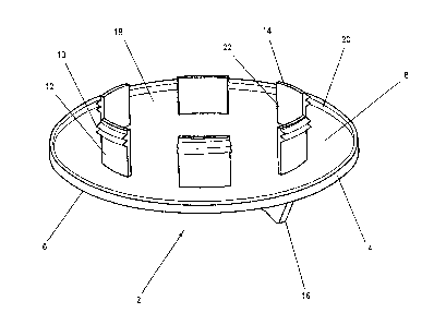
Figure 1 is a perspective view of a lower
surface of a closure with the closure turned up-side-
down;
Figure 2 is a top view of the closure; and
Figure 3 is a sectional side view of the
closure inserted into a bushing in a container.
Referring to the drawings in greater detail,
in Figures 1 and 2, the closure 2 has a cap portion 4
with an upper surface 6 and a lower surface 8 when the
closure is in an upright position. The lower surface
has interlocking means which are shown as screw
2S threads 10 located on an outer surface 12 of threadsupports 14. There are a plurality of spaced-apart
arcuate supports 14 extending away from the lower
surface 8. The supports 14 are arranged to form an
intermittent circle of a size that will fit snugly
within a tank opening ~not shown in Figures 1 and 2).
The upper surface 6 of the cap portion 4 contains
means 16 to rotate the closure 2 relative to the tank.
The means 16 is simply two ridges located 180 apart
-- 2 --

from one another that together ~orrn a handle to allow
the closure to be turned manually.
Preferably, the closure is made of a one
piece plastic material. There are various plastic
resins, for example, polyethylene, that will be
suitable.
Between each of the thread supports 14,
there is a space 18, there being six thread supports
and six spaces, the thread supports being
approximately the same size as the spaces. The cap
portion 4 has a circular shape and the lower surface
is generally flat with a flange 20 extending downward
from a periphery thereof. The flange 20 assists in
deflecting water away from the tank opening (not shown
in Figures 1 and 2).
The outer surface 12 of the thread supports
14 are substantially perpendicular to the lower
surface 8 of the cap portion 4~ An inner surface 22
of the thread supports 14 is situated at an angle of
substantially 2O relative to the outer surface 12, the
inner surface 22 tapering linearly from said outer
surface 12 towards the lower surface 8 of the cap
portion 4.
In F.igure 3, there is shown a tank fitting
24 mounted in a tank 26. The tank fitting 24 has a
threaded inner surface and is circular in shape. A
bushing 28 having threaded inner and outer surfaces
30, 32 respectively is threaded into the fitting 24.
Preferably, the bushing 28 is made of nylon. The
closure 2 is sized to fit within a tank opening 34 as
reduced in size by the fitting 24 in bushing 28. The
closure 2 has thread supports 14 containing
interlocking means, which are shown as screw threads
10 on an outer surface 12 thereof. The screw threads
-- 3 --

1 3 ~
10 of the closure 2 engage screw threads 29 on the
inner surface 30 of the bushing 28. The screw threads
29 can also be referred to as interlocXing means.
The closure 2 can be pushed into the opening
34 in a longitudinal direction. The thread supports
14 are flexible enough to bend slightly so that the
screw threads 10 will override the screw threads 29
until the lower surface 8 of the cap portion 4 abuts a
top surface 36 of the bushing 28. This can be
referred to as an installed position and is shown in
Figure 3. Once the closure 2 is in the installed
position, it is held in place by the engagement of the
screw threads 10 on the closure with the corresponding
screw threads 29 on the bushing. In this installed
position, air can enter and leave the tank 26 through
the air passages or spaces 18 between the thread
supports 14. However, the opening 34 is sufficiently
closed to prevent free-falling water, for example,
rain from entering the tank 26 through the opening 34.
When it is desired to remove the closure 2
from the opening 34, the closure can be manually
turned by applying a rotational force to the ridges
16, thereby turning the closure in an appropriate
direction relative to the tank 26. Usually, the
approprlate direction would be counterclockwise and
the screw threads 10, 29 would move relative to one
another until they became completely disengaged and
the closure 2 could then be completely removed from
the opening 34. Of course, the closure 2 can also be
removed from the opening 34 by prying or pulling with
a force greater than the holding force of the screw
thread 10. For example a suitable tool such as a vice
grips could be affixed to the handle 16 and t~e
closure can be forced longitudinally out of the
-- 4 --

13~&~
opening the screw threads on the closure overriding
the screw threads on the tank opening.
The closure can be designed to ~it within
virtually any size of tank opening. Numerous
variations, within the scope of the attached claims,
will be readily apparent to those skilled in the art.

Representative Drawing
A single figure which represents the drawing illustrating the invention.
Administrative Status

2024-08-01:As part of the Next Generation Patents (NGP) transition, the Canadian Patents Database (CPD) now contains a more detailed Event History, which replicates the Event Log of our new back-office solution.

Please note that "Inactive:" events refers to events no longer in use in our new back-office solution.

For a clearer understanding of the status of the application/patent presented on this page, the site Disclaimer , as well as the definitions for Patent , Event History , Maintenance Fee  and Payment History  should be consulted.

Event History

Description Date
Inactive: Expired (old Act Patent) latest possible expiry date 2010-06-01
Inactive: IPC from MCD 2006-03-11
Inactive: Reversal of will be deemed expired status 2001-07-11
Inactive: Office letter 2001-07-11
Letter Sent 2001-06-01
Inactive: Office letter 2000-06-08
Grant by Issuance 1993-06-01

Abandonment History

There is no abandonment history.

Owners on Record

Note: Records showing the ownership history in alphabetical order.

Current Owners on Record
CLEMMER INDUSTRIES LIMITED
Past Owners on Record
ELSON G. FERNANDES
Past Owners that do not appear in the "Owners on Record" listing will appear in other documentation within the application.
Documents

To view selected files, please enter reCAPTCHA code :


To view images, click a link in the Document Description column. To download the documents, select one or more checkboxes in the first column and then click the "Download Selected in PDF format (Zip Archive)" or the "Download Selected as Single PDF" button.

List of published and non-published patent-specific documents on the CPD .

If you have any difficulty accessing content, you can call the Client Service Centre at 1-866-997-1936 or send them an e-mail at CIPO Client Service Centre.


Document
Description 
Date
(yyyy-mm-dd) 
Number of pages   Size of Image (KB) 
Abstract 1994-02-17 1 19
Drawings 1994-02-17 3 34
Cover Page 1994-02-17 1 11
Claims 1994-02-17 2 59
Descriptions 1994-02-17 5 158
Representative drawing 2001-12-31 1 9
Fees 2003-05-28 1 31
Correspondence 2000-06-08 1 9
Fees 2000-05-30 1 31
Fees 1998-05-25 1 37
Fees 2002-05-29 1 33
Fees 2001-05-18 3 81
Fees 1999-06-01 1 32
Fees 2000-06-16 1 32
Fees 2004-05-31 1 31
Fees 2005-05-13 1 31
Fees 2006-05-24 1 28
Fees 2007-05-18 1 29
Fees 2008-05-14 2 65
Fees 2009-06-01 1 28
Fees 1997-05-20 1 41
Fees 1996-05-13 1 33
Fees 1995-05-18 1 36
Examiner Requisition 1992-02-19 1 54
Prosecution correspondence 1992-02-25 2 40
Prosecution correspondence 1992-10-30 2 52
Examiner Requisition 1992-06-30 1 76
PCT Correspondence 1993-03-16 2 32