Sélection de la langue

Search

Sommaire du brevet 1318640 

Énoncé de désistement de responsabilité concernant l'information provenant de tiers

Une partie des informations de ce site Web a été fournie par des sources externes. Le gouvernement du Canada n'assume aucune responsabilité concernant la précision, l'actualité ou la fiabilité des informations fournies par les sources externes. Les utilisateurs qui désirent employer cette information devraient consulter directement la source des informations. Le contenu fourni par les sources externes n'est pas assujetti aux exigences sur les langues officielles, la protection des renseignements personnels et l'accessibilité.

Disponibilité de l'Abrégé et des Revendications

L'apparition de différences dans le texte et l'image des Revendications et de l'Abrégé dépend du moment auquel le document est publié. Les textes des Revendications et de l'Abrégé sont affichés :

  • lorsque la demande peut être examinée par le public;
  • lorsque le brevet est émis (délivrance).
(12) Brevet: (11) CA 1318640
(21) Numéro de la demande: 1318640
(54) Titre français: DISPOSITIF DE FERMETURE TEMPORAIRE POUR RESERVOIRS
(54) Titre anglais: TEMPORARY CLOSURE FOR USE WITH STORAGE TANKS
Statut: Durée expirée - après l'octroi
Données bibliographiques
(51) Classification internationale des brevets (CIB):
  • B65D 39/00 (2006.01)
  • B65D 39/08 (2006.01)
(72) Inventeurs :
  • FERNANDES, ELSON G. (Canada)
(73) Titulaires :
  • CLEMMER INDUSTRIES LIMITED
(71) Demandeurs :
  • CLEMMER INDUSTRIES LIMITED (Canada)
(74) Agent: DARYL W. SCHNURRSCHNURR, DARYL W.
(74) Co-agent:
(45) Délivré: 1993-06-01
(22) Date de dépôt: 1988-10-06
Licence disponible: S.O.
Cédé au domaine public: S.O.
(25) Langue des documents déposés: Anglais

Traité de coopération en matière de brevets (PCT): Non

(30) Données de priorité de la demande: S.O.

Abrégés

Abrégé anglais


ABSTRACT
A temporary closure for containers such as
storage tanks and the like has a cap portion with
arctuate thread supports extending downward from a
lower surface of the cap portion. The outer surface
of the thread supports has screw threads thereon, the
screw threads corresponding to screw threads on an
inner surface of a tank opening. The closure is made
of a one piece plastic material and the thread
supports are flexible enough so that the closure can
be quickly and easily inserted longitudinally into the
tank opening with the screw threads on the closure
overriding the screw threads in the tank opening. The
closure is held in place in the tank opening by the
screw threads and can be removed by turning or by
prying the closure out of the opening with a suitable
tool.

Revendications

Note : Les revendications sont présentées dans la langue officielle dans laquelle elles ont été soumises.


The embodiments of the invention in which an exclusive
property or privilege is claimed are defined as
follows:
1. A temporary closure for use with an opening
in storage tanks or the like, said opening having
screw threads located on an inner surface, said
closure comprising a cap portion and being made of a
slightly flexible but rigid material, said cap portion
having an upper and lower surface when said closure is
in an upright position, a plurality of spaced apart
arcuate thread supports extending away from said lower
surface, said supports having screw threads on an
outer surface thereof, said screw threads together
corresponding to screw threads in the tank opening,
said thread supports being arranged to form an
intermittent circle of a size that will fit snugly
within the tank opening with the screw threads of the
tank engaged with the screw threads of the closure,
the upper surface of the cap portion containing means
to rotate the closure, the thread supports being
flexible enough so that the closure can be pushed into
the tank opening in a longitudinal direction until the
lower surface of the cap portion abuts the outer
surface of the tank opening and the screw threads of
the closure are engaged with the screw threads of the
tank, the closure being removable from the tank
opening by rotating the closure in an appropriate
direction.
2. A closure as claimed in Claim 1 wherein the
closure is made of a one-piece plastic material.
3. A closure as claimed in Claim 1 wherein the
thread supports are approximately equal in size to the
spaces between the thread supports.

4. A closure as claimed in any one of Claims 1,
2 or 3 wherein the cap portion has a circular shape
and the lower surface is generally flat with a flange
extending downward from a periphery of the cap
portion, the flange assisting in deflecting water away
from the tank opening.
5. A closure as claimed in Claim 2 wherein the
thread supports have an outer surface that is
substantially perpendicular to the lower surface of
the cap portion and an inner surface that is at an
angle of substantially 2° relative to the outer
surface, the inner surface tapering linearly away from
said outer surface towards the lower surface of said
cap portion.
6. A closure as claimed in any one of Claims 1,
2 or 3 wherein the means to rotate the closure are two
ridges, located 180° apart from one another on an
upper surface of the cap portion, said ridges together
forming a handle so that the closure can be removed
manually.

Description

Note : Les descriptions sont présentées dans la langue officielle dans laquelle elles ont été soumises.

~3186~0
This invention relates to a temporary
closure ~or use with an opening in containers such as
storage tanks or the like. In particular, the
temporary closure can be placed in a tank opening in a
longitudinal direction but cannot be easily removed
unless it is rotated relative to the tank opening.
Temporary closures for storage tanks are
known. Unfortunately, previous temporary closures do
not tightly close the tank opening; or, they can be
pulled entirely into the tank or forced outwardly from
the opening by pressure changes within the tank; or,
they are cumbersome to install or remove; or, they do
not permit the passage of air into or out of the tank;
or, they do not prevent the entry of free-falling
water into the tank; or, they are too complex or too
expensive to manufacture.
It is an object of the present invention to
provide a temporary closure for containers such as
storage tanks or the like that can be quickly inserted
into a tank opening, but once inserted will not be
removed through pressure changes within the tank.
A temporary closure for use with an opening
in containers such as storage tanks or the like where
the tank opening has interlocking means located on an
inner surface, said closure has a cap portion. The
closure is made of a slightly flexible but rigid
material and the cap portion has an upper and lower
surface when the closure is in an upright position.
The lower surface has interlocking means extending
therefrom, the interlocking means on the closure
corresponding to the interlocking means on the tank
opening. the interlocking means are arranged so that
the interlocking means on the closure engages the
-- 1 --

interlocking means on the tank opening when the
closure is pushed longitudinally into the tank opening
with the cap portion covering the opening. The cap
portion contains means to rotate the closure relative
to the opening, the interlocking means of the closure
becoming disengaged from the interlocking means of the
tank opening when the closure is rotated in an
appropriate direction, relative to the tank, the
closure has one or more air passages to allow air to
pass into or out of the tank through the closure when
the closure is installed in the tank opening.
In drawings which illustrate a preferred
embodiment of the invention:
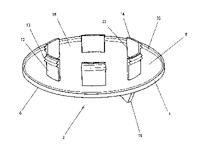
Figure 1 is a perspective view of a lower
surface of a closure with the closure turned up-side-
down;
Figure 2 is a top view of the closure; and
Figure 3 is a sectional side view of the
closure inserted into a bushing in a container.
Referring to the drawings in greater detail,
in Figures 1 and 2, the closure 2 has a cap portion 4
with an upper surface 6 and a lower surface 8 when the
closure is in an upright position. The lower surface
has interlocking means which are shown as screw
2S threads 10 located on an outer surface 12 of threadsupports 14. There are a plurality of spaced-apart
arcuate supports 14 extending away from the lower
surface 8. The supports 14 are arranged to form an
intermittent circle of a size that will fit snugly
within a tank opening ~not shown in Figures 1 and 2).
The upper surface 6 of the cap portion 4 contains
means 16 to rotate the closure 2 relative to the tank.
The means 16 is simply two ridges located 180 apart
-- 2 --

from one another that together ~orrn a handle to allow
the closure to be turned manually.
Preferably, the closure is made of a one
piece plastic material. There are various plastic
resins, for example, polyethylene, that will be
suitable.
Between each of the thread supports 14,
there is a space 18, there being six thread supports
and six spaces, the thread supports being
approximately the same size as the spaces. The cap
portion 4 has a circular shape and the lower surface
is generally flat with a flange 20 extending downward
from a periphery thereof. The flange 20 assists in
deflecting water away from the tank opening (not shown
in Figures 1 and 2).
The outer surface 12 of the thread supports
14 are substantially perpendicular to the lower
surface 8 of the cap portion 4~ An inner surface 22
of the thread supports 14 is situated at an angle of
substantially 2O relative to the outer surface 12, the
inner surface 22 tapering linearly from said outer
surface 12 towards the lower surface 8 of the cap
portion 4.
In F.igure 3, there is shown a tank fitting
24 mounted in a tank 26. The tank fitting 24 has a
threaded inner surface and is circular in shape. A
bushing 28 having threaded inner and outer surfaces
30, 32 respectively is threaded into the fitting 24.
Preferably, the bushing 28 is made of nylon. The
closure 2 is sized to fit within a tank opening 34 as
reduced in size by the fitting 24 in bushing 28. The
closure 2 has thread supports 14 containing
interlocking means, which are shown as screw threads
10 on an outer surface 12 thereof. The screw threads
-- 3 --

1 3 ~
10 of the closure 2 engage screw threads 29 on the
inner surface 30 of the bushing 28. The screw threads
29 can also be referred to as interlocXing means.
The closure 2 can be pushed into the opening
34 in a longitudinal direction. The thread supports
14 are flexible enough to bend slightly so that the
screw threads 10 will override the screw threads 29
until the lower surface 8 of the cap portion 4 abuts a
top surface 36 of the bushing 28. This can be
referred to as an installed position and is shown in
Figure 3. Once the closure 2 is in the installed
position, it is held in place by the engagement of the
screw threads 10 on the closure with the corresponding
screw threads 29 on the bushing. In this installed
position, air can enter and leave the tank 26 through
the air passages or spaces 18 between the thread
supports 14. However, the opening 34 is sufficiently
closed to prevent free-falling water, for example,
rain from entering the tank 26 through the opening 34.
When it is desired to remove the closure 2
from the opening 34, the closure can be manually
turned by applying a rotational force to the ridges
16, thereby turning the closure in an appropriate
direction relative to the tank 26. Usually, the
approprlate direction would be counterclockwise and
the screw threads 10, 29 would move relative to one
another until they became completely disengaged and
the closure 2 could then be completely removed from
the opening 34. Of course, the closure 2 can also be
removed from the opening 34 by prying or pulling with
a force greater than the holding force of the screw
thread 10. For example a suitable tool such as a vice
grips could be affixed to the handle 16 and t~e
closure can be forced longitudinally out of the
-- 4 --

13~&~
opening the screw threads on the closure overriding
the screw threads on the tank opening.
The closure can be designed to ~it within
virtually any size of tank opening. Numerous
variations, within the scope of the attached claims,
will be readily apparent to those skilled in the art.

Dessin représentatif
Une figure unique qui représente un dessin illustrant l'invention.
États administratifs

2024-08-01 : Dans le cadre de la transition vers les Brevets de nouvelle génération (BNG), la base de données sur les brevets canadiens (BDBC) contient désormais un Historique d'événement plus détaillé, qui reproduit le Journal des événements de notre nouvelle solution interne.

Veuillez noter que les événements débutant par « Inactive : » se réfèrent à des événements qui ne sont plus utilisés dans notre nouvelle solution interne.

Pour une meilleure compréhension de l'état de la demande ou brevet qui figure sur cette page, la rubrique Mise en garde , et les descriptions de Brevet , Historique d'événement , Taxes périodiques et Historique des paiements devraient être consultées.

Historique d'événement

Description Date
Inactive : Périmé (brevet sous l'ancienne loi) date de péremption possible la plus tardive 2010-06-01
Inactive : CIB de MCD 2006-03-11
Inactive : Renversement de l'état sera réputé périmé 2001-07-11
Inactive : Lettre officielle 2001-07-11
Lettre envoyée 2001-06-01
Inactive : Lettre officielle 2000-06-08
Accordé par délivrance 1993-06-01

Historique d'abandonnement

Il n'y a pas d'historique d'abandonnement

Titulaires au dossier

Les titulaires actuels et antérieures au dossier sont affichés en ordre alphabétique.

Titulaires actuels au dossier
CLEMMER INDUSTRIES LIMITED
Titulaires antérieures au dossier
ELSON G. FERNANDES
Les propriétaires antérieurs qui ne figurent pas dans la liste des « Propriétaires au dossier » apparaîtront dans d'autres documents au dossier.
Documents

Pour visionner les fichiers sélectionnés, entrer le code reCAPTCHA :


Pour visualiser une image, cliquer sur un lien dans la colonne description du document. Pour télécharger l'image (les images), cliquer l'une ou plusieurs cases à cocher dans la première colonne et ensuite cliquer sur le bouton "Télécharger sélection en format PDF (archive Zip)" ou le bouton "Télécharger sélection (en un fichier PDF fusionné)".

Liste des documents de brevet publiés et non publiés sur la BDBC .

Si vous avez des difficultés à accéder au contenu, veuillez communiquer avec le Centre de services à la clientèle au 1-866-997-1936, ou envoyer un courriel au Centre de service à la clientèle de l'OPIC.


Description du
Document 
Date
(aaaa-mm-jj) 
Nombre de pages   Taille de l'image (Ko) 
Abrégé 1994-02-17 1 19
Dessins 1994-02-17 3 34
Page couverture 1994-02-17 1 11
Revendications 1994-02-17 2 59
Description 1994-02-17 5 158
Dessin représentatif 2001-12-31 1 9
Taxes 2003-05-28 1 31
Correspondance 2000-06-08 1 9
Taxes 2000-05-30 1 31
Taxes 1998-05-25 1 37
Taxes 2002-05-29 1 33
Taxes 2001-05-18 3 81
Taxes 1999-06-01 1 32
Taxes 2000-06-16 1 32
Taxes 2004-05-31 1 31
Taxes 2005-05-13 1 31
Taxes 2006-05-24 1 28
Taxes 2007-05-18 1 29
Taxes 2008-05-14 2 65
Taxes 2009-06-01 1 28
Taxes 1997-05-20 1 41
Taxes 1996-05-13 1 33
Taxes 1995-05-18 1 36
Demande de l'examinateur 1992-02-19 1 54
Correspondance de la poursuite 1992-02-25 2 40
Correspondance de la poursuite 1992-10-30 2 52
Demande de l'examinateur 1992-06-30 1 76
Correspondance reliée au PCT 1993-03-16 2 32