Language selection

Search

Patent 1318764 Summary

Third-party information liability

Some of the information on this Web page has been provided by external sources. The Government of Canada is not responsible for the accuracy, reliability or currency of the information supplied by external sources. Users wishing to rely upon this information should consult directly with the source of the information. Content provided by external sources is not subject to official languages, privacy and accessibility requirements.

Claims and Abstract availability

Any discrepancies in the text and image of the Claims and Abstract are due to differing posting times. Text of the Claims and Abstract are posted:

  • At the time the application is open to public inspection;
  • At the time of issue of the patent (grant).
(12) Patent: (11) CA 1318764
(21) Application Number: 586766
(54) English Title: TWO PIECE DUST CONTROL MAT
(54) French Title: TAPIS-BROSSE EN DEUX PARTIES
Status: Deemed expired
Bibliographic Data
(52) Canadian Patent Classification (CPC):
  • 20/54
  • 15/98
(51) International Patent Classification (IPC):
  • A47L 23/26 (2006.01)
  • A47G 27/04 (2006.01)
(72) Inventors :
  • KERR, ROBERT CHARLES (United States of America)
  • MURRAY, JOHN H. (United States of America)
(73) Owners :
  • MILLIKEN RESEARCH CORPORATION (United States of America)
(71) Applicants :
(74) Agent: GOWLING WLG (CANADA) LLP
(74) Associate agent:
(45) Issued: 1993-06-08
(22) Filed Date: 1988-12-22
Availability of licence: N/A
(25) Language of filing: English

Patent Cooperation Treaty (PCT): No

(30) Application Priority Data:
Application No. Country/Territory Date
146,080 United States of America 1988-01-20

Abstracts

English Abstract


ABSTRACT OF THE DISCLOSURE

A two-piece dust control mat having an upper pile fabric portion and a
lower rubber-like base portion. The under surface of the upper portion and
the upper surface of the lower portion are treated to increase the friction
resistance therebetween and in the preferred form the treatment consists of
providing interlocking cleat members.


Claims

Note: Claims are shown in the official language in which they were submitted.


CLAIMS
1. The method of providing clean dust control mats
comprising the steps of: laying down a durable
rubber-like base mat having cleats on the upper
surface, providing a light weight launderable pile
fabric with cleats on the bottom thereof, placing the
pile fabric into engagement with the rubber-like base
mat by interlocking the cleats of the pile fabric and
the base mat and removing the pile fabric from the base
mat when it becomes soiled and replacing it with
another pile fabric having cleats on the bottom surface
which interlock with the cleats on the upper surface of
the base mat.
2. A dust control mat comprising a durable rubber-like
mat material and a light weight launderable pile fabric
mat on top of and engaging the rubber-like base mat
characterised in that the upper surface of the base mat
and the under surface of the pile fabric mat are each
provided with cleats which provide a non-sliding
engagement between said pile fabric mat and said
rubber-like base mat.

3. A dust control mat as claimed in Claim 2 wherein
said pile fabric mat is mounted centrally of said base
mat and is of such a size that it does not extend
outwardly to the edges of said base mat.

4. A dust control mat as claimed in Claim 2 wherein
said pile fabric mat includes a substrate with yarns
tufted therein and extending upwardly away from the
under surface thereof.

5. A dust control mat as claimed in Claim 4 wherein


the cleated surface of said pile fabric mat is a thin
layer of rubber-like material molded thereon.
6. A dust control mat as claimed in Claim 5 wherein
said pile fabric is mounted centrally of said base mat
and is of such a size that it does extend outwardly to
the edge of said bass mat.

7. A dust control mat as claimed in Claim 6 wherein
cleats are formed on the under surface of said
rubber-like base mat to and in the prevention of
slippage of said mat to provide skid resistance
thereto.

8. A dust control mat as claimed in Claim 7 wherein
said base mat has cleats on the other side of said mat
to provide said resistance to said mat.

Description

Note: Descriptions are shown in the official language in which they were submitted.


r~ ~ ~
Case Number 164n

TWO PlECE DUST CONTROL MAT
This invention relates generally to rubber-backed dust control f100r
mats of the type which have a pile surface on one side and a rubber or
rubber-like material on the other side. Mats of this type are generally
used in access ways where people tend to brush or scrape their feet in
order to pr~vent carrying of moisture and/or dirt, accumulated on their
footwear, into other areas of the premises. Normally these mats are
located in areas of high pedestrian traffic, such as doorways.
The rubber-backed dust control mat, historically, has been an
integrated structure in which the rubber-like backing has been laminated
and/or molded to the undersurface of the pile fabric to provide a unitary
structure. rhis provides a strong mat with a long service life but has the
disadvantage that the weight and volullle of the rubber backing material
requires a large washing capacity and at the same time exposes the rubber
material to high heat every time the mat is washed and dried. This high
heat has a deleterious effect on the rubber-like material over a period of
time resulting in a shorter service life.
~ It is therefore an object of the invention to provide a two-piece dust
control mat which reduces the required washing load for dust control mats
and eliminates the drying of the foundation rubber-like backing material.
Other objects and advantages of the invention will become readily
apparent as the specification proceeds to describe the invention with
reference to the accompanying drawing, in which:
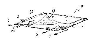
Figure 1 shows an interconnected two piece dust control mat;
Figure 2 is section view of the rubber-like backing strip used in
Figure I and
Figure 3 is a sectional view taken on line 3-3 of Figure 1.


131~7 ~

Looking now to the drawings and especially Figure 1 ~here is shown a
dust control mat 10 consisting basically of a pile fabric 12 and a
rubber-like base mat 14 on which the fabric 12 is placed. To prevent
slippage between the mat 12 and the base 1~ the upper surface of the base
14 and the lower surface of the mat 12 is treated to increase the friçtion
resistance therebetween.
~ n the preferred form of the invention the pile fabric 12 consists of
pile yarns 16 of cotton, nylon, etc. tufted through a woven or nonwoven
substrate 18 of suitable material. To provide a frict10n resistant bottom
a thin rubber-like material 20 is molded or otherwise secured to the bottom
of the fabric 12 and has a plurality of cleats 22 formed therein in any
suitable design to interlock with the cleats 24 on the upper surface of the
rubber-like base mat 14. This material is about 50,~ less than that in the
backing of a unitary ma-t.
The base mat or strip 14 of rubber or other suitable material has
cleats 24 on the upper surface thereof for reasons previously set forth.
The mat 14 also has cleats 28 on the bottom thereof in any suitable pattern
which, like cleats 22, act as friction resistant elements to resist
creeping to minimize movement nf the carpets on the surface on which it is
placed.
Currerltly, as mentioned above, the dust control mat 10 is made as a
unit and i5 as such provided to rental laundries. The rental laundries
rent the mats 10 to a user of a period basis of a week, month, etc. Then
the rental laundry picks up the mat, replaces it with a clean mat and takes
the soiled mat back for cleaning. Since the rubber-like backing material
is fairly thick and heavy only a preselected number of mats can be washed
and dried at one time. This process is slow due to the small number of
mats that can be processed at one time and has a harsh, deleterious ef-fect
on the rubber-like material due to repeated washing and drying of same.

~3~ 87 ~


The herein-described mat 10 eliminates several nf these disadvantages
The rental laundry now can place base mat 14 in situ at its customer's
location and merely remove and replace the pile fabric 12. The cleats 22
on the bottom of pile fabric 12 allow it to be placed in a fixed position
of the rubber-liké base 14 by interengagement with the cleats 24 on the
upper surface thereof. ~hus, when the pile fabric 12 becomes soi1ed it can
be removed from the base 14 and replaced by a clean pile fabric. Then, it
is obvious that it is easier to wash and dry only the pile fabric 12 than
the unitary dust control mat. Furthermore, the consumption of energy is
less since there is less material to wash and dry. During the removal,
replacement and washing of the pile fabric the base rubber-like material
remairls in situ at the customer's location with its lower cleats engaging
the sur-face on which it has been placed.
As pointed out beFore, the lower surface of the pile fabric 12 and the
upper surface of the base mat 14 are treated to increase the friction
resistance so that one will not slide relative to another and remain in
interengagement. In the preferred form of the invention this treatment
involves the formation of cleats therein but other methods may be employed.
For example, the undersurface of the fabric 12 could be coated with latex,
foamed latex, a rubber/vinyl material, foamed rubber, hot melts, etc.,
while the rubber-like mat 14 surface could be coated like above, embossed
or textured to provide a cooperating surface. Other combinations are
possible so long as the mating surfaces are treated to provide a releasable
engaging connection between the pile fabric 12 and rubber-like base mat 14.
It can readily be seen that a dust control mat has been described which
provides the efficiency of that which is currently being used but allows
savings in replacement time, washing, reduction in energy cost and
increases the service life of the rubber component of the mat resulting in
reduced capital investlllent.


~3~7~

Although the preferred embodiment of the invention has been described,
it is contemplated that many changes may be made without departing from the
scope or spirit of the invention and it is desired that the claims be
limited only by the claims.

Representative Drawing
A single figure which represents the drawing illustrating the invention.
Administrative Status

For a clearer understanding of the status of the application/patent presented on this page, the site Disclaimer , as well as the definitions for Patent , Administrative Status , Maintenance Fee  and Payment History  should be consulted.

Administrative Status

Title Date
Forecasted Issue Date 1993-06-08
(22) Filed 1988-12-22
(45) Issued 1993-06-08
Deemed Expired 2006-06-08

Abandonment History

There is no abandonment history.

Payment History

Fee Type Anniversary Year Due Date Amount Paid Paid Date
Application Fee $0.00 1988-12-22
Registration of a document - section 124 $0.00 1989-03-20
Maintenance Fee - Patent - Old Act 2 1995-06-08 $100.00 1995-03-30
Maintenance Fee - Patent - Old Act 3 1996-06-10 $100.00 1996-03-29
Maintenance Fee - Patent - Old Act 4 1997-06-09 $100.00 1997-04-04
Maintenance Fee - Patent - Old Act 5 1998-06-08 $150.00 1998-03-23
Maintenance Fee - Patent - Old Act 6 1999-06-08 $150.00 1999-03-19
Maintenance Fee - Patent - Old Act 7 2000-06-08 $150.00 2000-03-20
Maintenance Fee - Patent - Old Act 8 2001-06-08 $150.00 2001-03-19
Maintenance Fee - Patent - Old Act 9 2002-06-10 $150.00 2002-03-28
Maintenance Fee - Patent - Old Act 10 2003-06-09 $200.00 2003-03-24
Maintenance Fee - Patent - Old Act 11 2004-06-08 $250.00 2004-05-25
Owners on Record

Note: Records showing the ownership history in alphabetical order.

Current Owners on Record
MILLIKEN RESEARCH CORPORATION
Past Owners on Record
KERR, ROBERT CHARLES
MURRAY, JOHN H.
Past Owners that do not appear in the "Owners on Record" listing will appear in other documentation within the application.
Documents

To view selected files, please enter reCAPTCHA code :


To view images, click a link in the Document Description column. To download the documents, select one or more checkboxes in the first column and then click the "Download Selected in PDF format (Zip Archive)" or the "Download Selected as Single PDF" button.

List of published and non-published patent-specific documents on the CPD .

If you have any difficulty accessing content, you can call the Client Service Centre at 1-866-997-1936 or send them an e-mail at CIPO Client Service Centre.


Document
Description 
Date
(yyyy-mm-dd) 
Number of pages   Size of Image (KB) 
Examiner Requisition 1991-07-02 1 16
Prosecution Correspondence 1991-10-17 2 31
Examiner Requisition 1992-02-19 1 56
Prosecution Correspondence 1992-08-18 2 45
PCT Correspondence 1993-03-17 1 18
Description 1993-11-17 4 128
Representative Drawing 2000-08-15 1 8
Drawings 1993-11-17 1 28
Claims 1993-11-17 2 64
Abstract 1993-11-17 1 10
Cover Page 1993-11-17 1 14
Fees 1997-04-04 1 44
Fees 1996-03-29 1 36
Fees 1995-03-30 1 37