Note: Descriptions are shown in the official language in which they were submitted.
~ t~8815
The present invention concerns a planting tube through which the
operator doing the planting drops the s~edling into the earth,
into a hole made by the tube. The planting tube meant ~or
seedlings comprises a tube provided with a handle and having on
its lower end a fixed jaw to which has been ]pivotally attached
a turnable jaw which can be moved with the aid of a pedal.
In prior art seedling planting means of similar kind are known,
which have been described, for instance, in the Swedish patent
publication Nos. 443697 and 443071, published February 13, 1985
and April 29, 1984, respectively, in the Finnish Patents Nos.
50033 and 63318, and in the Finnish patent application No.
850549, published August 9, 1986. In ~hese reEerences the
planting tube is provided with a blade producing a planting
hole, said blade consisting of a fixed jaw and an openable ~aw
pivotally attached thereto. This openable jaw can be opened to
its planting position with the aid of a pedal lever. The
movable jaw can thereafter be locked in position with the aid
of a locking means. In these designs of prior art the movable
jaw opens on depressing the pedal always in the direction away
from the operator. It follows that after a seedling has been
planted, the operator must move over to the side beyond the
seedling so that he may properly compact around the seedling the
soil which the turning jaw has displaced. Since the planting
work is done on a job-rate basis, which is characterized by
great hurry, this earth compacting has not been done well
enough, as tests that have been carried out show; the seedlings
have instead come loose when pulled.
The object of the present invention is to eliminate the
drawbacks occurring in connection with existing means and to
provide a seedling planting means with which positive planting
results are achieved with ease and in orthodox manner, without
incurring slow or difficult plantirlg ........................
~k
J" ~
1318815
work At the same time~ the aim is to provide a durable~
ergonomic and reliable implement ih which the moYing
parts are replace~ble. rhis aim is achieved by construct-
ing a planting tube on which the Dpenable iaw faces the
operator instead of facinL7 ~w~y from him as is the case
in planting tube~ of p~~ior art.
The planting tube of -the invention is characteri~ed in
that the tLIrning jaw comprises~ above the pivot arrange-
ment connecting it with the fi~ed jaw, ~ pivot s~lpport~
and the pedal comprises a loop~ such as a suitable slit~
in which the pivot ~pport can move. Hereby~ when the
pedal is depressed7 said loop and piYot support tr~7nsmit
the pedal movement to produce a movement opening the
turnir7g jaw. Said pivot support and loop are character-
i~ed in that ~hey can move relative to each other7 yet
staying in constant contact. This relatiYe movement is
indispensable hecause jaw and pedal have been pivoted on
the tuke at separate points and therefore cannot have a
cumn,on -fulcrum when they turn. It is o~viQus that the
inventior, also coi~ers a means in whi{h the pivot support
is located on the pedal and the loop~ on the turning jaw.
The invention is descri~ed in the following in clQser
detail with the aid of one of its embodiments~ and r-efer-
ence being made at the came time to the drawings~ where-
in:-
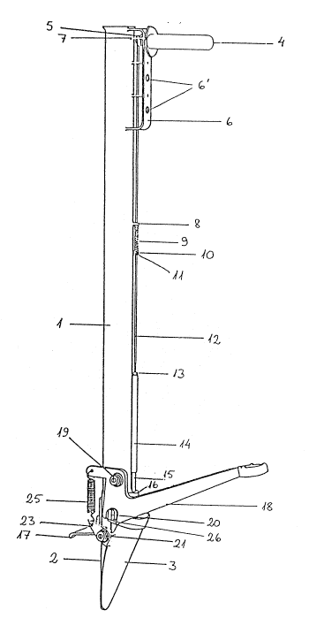
Fig. 1 presents the planting means in a~:onometric pr-o-
jection, seen fr-om the left~ from the operator s posi-
tion 5 and
Fig. ~ shows the blade portion of the planting means~
seen from the right~ from the operator s position.
The pl~nting tube of the invention comp~ises a t~lbe 1
provided with a h~ndle 4 on its upper end~ the seedling
being dropped through its top end into the hole thc~t has
been made by the planting tube~ The~ tu~e 1 carries on its
lclwer end two j~W5 r~ which~ when clr-sed~ constitute ~
1318815
blade -for drivinq the planting tLIbe into the ground. Qne
o-F the jaws~ ' 3 is fi~:ed and is att~ched to the tube 1
e~g~ by weldiny~ Orl this fixed jaw has been mounted~ e.g.
with a bolt and nut~ a plantinL~7 depth limi~e~ 17~ which
has Dn its end a vertically dDwnward angL~lated member3
w,hich as it enter~s the soil ensLIreS th~t the planting
tL~be remains immovable once it has been driven into the
ground. The dep-th limiter 17 may~ when desired~ also be
used to a55.is t when the tube is being driven into the
9rOLlnd 5 by pressing it down with one foot.
On the ~ixed jaw ~ in the centre-line plane of the tube
t~ two pivot bolts ~1~ have been moLInted by which the
turning jaw ~ is pivoted to the fi~.ed jaw. The part of
the tLlrning jaw ~ below the pivot bolts ~ may be
narrower than the fi;:ed jaw ~. In that case the turning
jaw will displace the earth ahead of its~lf with greater
ease because3 at d~-iving the tube into the groL~nd5 the
fi~:ed jaw ~ h~s aIready cle7ft the soil layer. To the same
purpose the turning~jaw may also be prDvided with a long-
itLldinal ridgeu If moreover the part below the pivot
bolts ~1~2~- of the turning iaw is slightly shorter than
the equivalent part of the fi~ed jaw ~ the 7~ixed jaw
will remain stationary while the turning iaw moves earth
away.
The turning iaw -. carries in it~ upper part a pivot screw
2-) provided with a bearing roller and accommodateL7 in the
loop ~6 07r the pedal 1~ The loop ~ is U-shaped because
the openable jaw ~ rises upward somewhat when it is being
opened. The loop has furthermDre been 50 c7imensioned that
contact with the turning jaw is maintained all the time~
no matter whether the pedal 1~ is pressed down with the
foot or loaded with the spr-ing ~5. The pedal 1~ comprises
a hearing sleeve~ fi-tted into the hole~ for tLIrnable
attachment of the pedal witth a bolt 1~ to the t:ube 1.
hore~ver~ to the 1LI9 ~ of the left pivot bolt ~1 of -the
tnr-nirlg jaw ~ is ~ttached a spr-ing ~ its ot:her end
~318815
attached to a lug on the o~lter end of the pedal. The
right-hand pivot bolt ~ of the t~lrning jaw ~ eng~ges
with the right-hand 1U9 ~4 . When the pedal 18 i5 pressed
down with the foot~ the upper end of the turning jaw ~. is
pushed towards the t~lbe I by the pivot sLrew ~r-~ in the
loop ~6 of the pedal; at the same time the lower end of
the jaw ~ opens so -that a seedling can be dropped through
the planting tube and into the hole which the tLIrning iaw
~ has made in the ground.
The locking mechanism provided for the turning j~w com-
prises a slide 1~ which moves vertically reciprocatingly
in a guide plate 15 a-ffi;.ed to the side of the tube 1.
The slide carries as its e~:tension a sleeve 14~ with a
thread on its upper end~ the triggering rod 1~ being
attached on this thread The sleeve is locked relative to
the triggering rod with a locking nut l~y also serving
adjustment of the vertical position of the slide 15. The
locking s{rew 11 att~ches to the triggering rod i~ a
slee~e 10~ ~hich rests against the spring q of the trig-
gering rod~ The spring 9 is a compression spring~ resting
with its upper end against the spring rest ~ in which a
hole has been made for the triggering rod 1~. The upper
end of the triggering rod l~ attaches to a toggle lever
7j this lever is operated for instance with the thumb of
the right hand~ pressing down one end of the lever.
When the pedal 18 is pressed down frorr, the position de-
picted in Fig~ 1 into that of Fig. ~ the turning jaw ~
which faces the operator~ opens and makes a hole for the
seedling which i5 being planted. As the jaw ~ turns~ the
spring ~5 comes under tension. As soon as the upper
margin of the turning jaw hits the rounded lower end of
the slide 15~ the jaw ~ pushes the slide 15 L~pwards and
the triggering rod 1~ connected to the slide causes com-
pression r~f the spring q. In the further course of tLIrn-
ing of the jaw ~I the slide 15 finally slips o~er to the
other- ;ide of the iaw 5 -top end~ and the rompre~sior) of
```- 1318815
the spring ~ is released. The slide 1~ then descends and
locks the -turning jaw ~ in the pDsltion showrl in Fig. ~5
~ it se-ttles against the upper m~rgin of the jaw. The
seedling may now be in~er-ted :in the upper end of the
plantinr~ tube
After the planting process has been completed~ the opera
tor pt-esses down one end of the toggle lever 7 with the
thumb on his right hand~ whereby the triggering rod
ascends~ compresing the spring ~ once again. ~t the same
time the slide 15 ascends enDugh to release the turning
jaw ~.~ and by action of the spring 5 the turning jaw ~.
closes a~ainst the fi~:ed jaw ~ and the pedal 1~ cornes
up. The planting:tube is now ready to be dri~en into the
ground for depositing the ne~:t seedling. Compa[tion of
the soil material is an easy operation at this stage
because the soil matter pushed aside by the planting tube
was displaced towards the operator~ Cornpaction is in this
case e-ffected using:the ball of the foot. Hereby damage
o the seedling is also excluded~
For adJusting the planting tube to be properly dimen-
sioned for each individual operator -the handle 4 in the
upper part of the tubè 1 has been attached with a nut
on~an ad~ustment arc 6 ha~ing hQles ~ for mounting the
handle at a suitable height. The handle 4 i5 proYided
with a resilient:pad for damping the jolt prodllced when
tlle implement is driven into the groundr
It is ob~ious to a person skilled in the art that differ-
ent emhodiments of the invention are not confined to the
foregoing e~:ample and that they may vary within the scope
uf the claims following below.