Note: Descriptions are shown in the official language in which they were submitted.
1319135
-- 1 --
SOLENOID CONTROI. VALVE
This invention relates to solenoid control valves in
general and more particularly to armatures for high speed
electromagnetic solenoids as may be found in adaptive
braking systems.
BACRGROUND OF INVENTION
Adaptive braking systems require very fast response
times of the several electromechanical parts in order to
be effective. One of the many components of the system
are solenoid operated valves and pumps.
SUNMaRY 0~ INVENTION
The solenoid control valve accordiny to one aspect of
this invention has a first body member with an inlet
means at one end and a second body member extending
therefrom. Enclosing the other end of the second body
member is an insert member having a base portion and a
circular rib extending from the base portion to define a
cavity. A solenoid encircles the rib. Located in the
first body member is a ball valve means between the inlet
means and a plunger cavity. The ball valve means is
biased by a first spring means to a closed position for
preventing the flow of fluid ~rom the inlet means to the
plunger cavity.
A plunger is located in the plunger cavity and moves
reciprocally therein from one position opening the ball
valve means to another position allowing the ball valve
means to close. An armature is located in the cavity
defined by the circular rib, and is normally biased in a
position abutting the plunger and operable by the solenoid
~ I
131ql35
to reciprocally move in the cavity to move the plunger
for opening the ball valve means. The armature has at
least one passageway axially extending longitudinally
from the one end adjacent the plunger to the other end.
The one end of the armature has a circular groove
intersecting the at least one passageway.
Therefore, in an adaptive braking system having a
solenoid operated colltrol valve for receiving fluid at
one end thereof, a valve means adjacent the one end and
biased closed, a plunger means reciprocally actuated to
open the valve means, a solenoid means having an armature
normally biased into contact with the plunger means, the
improvement, according to the present invention
comprises: the armature having at least one aperture
axially extending for allowing passage of fluid
therethrough from one end thereof to the other end when
the armature is moved by the energizing of the solenoid
means for effecting the opening of the valve means and;
circular groove means at one end thereof in contact with
the plunger means and intersecting the aperture for
reducing the adhesion between the armature and the
plunger.
Many other objects and purposes of the invention will
be clear from the following detailed description of the
drawings.
BRIEF DESCRIPTION OF THE DRaWINGS
In the Drawings:
FIGURE 1 is an axially extending sectional view of a
solenoid valve illustrating the preferred embodiment of
the armature therein.
FIGURE 2 is a top view of a plunger in the preferred
embodiment of the valve.
FIGURE 3 is a plan view of the plunger of FIGURE 2.
~....
~319135
- 2a -
FIGURE 4 is a section view taken alo~g line 4-4
of FIGURE 3.
FIGURE 5 is ~a top view of the preferred
embodiment of the armature.
FIGURE 6 is a sectional plan view of the
preferred embodiment of the armature taken along line
6-6 of FIGURE 5.
FIGURE 7 is a top view of another embodiment of
the armature.
DETAILED DESCRIPTION OF THE PREFERRED EMsoDIMENT
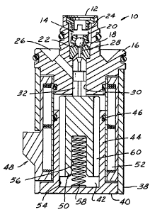
FIGURE 1 is a sectional plan view of a solenoid
control valve 10 as may be used in an adaptive
braking system. In particular this valve 10 is a
build or decay valve. Its function is to pulse fluid
21RCW1086/5812A 580-86-0080
--3--
1319135
at high speed to and from the wheel cylinders of the
vehicle during an anti-skid event to bring the
vehicle to a safe stop or under control.
Fluid enters the solenoid control valve 10
through the inlet 12 at one end thereof through a
ball valve means 14 located in a first body member
16. The ball valve means 14 comprises a ball 18, a
ball carrier 20, a valve seat 22 and a first spring
means 24. The ball valve means 14 is normally biased
in a closed condition by the first spring means 24
interconnected between the inlet of the solenoid
control valve 10 and the ball carrier 20. The ball
carrier 20, under the influence of the first spring
means 24, moves the ball 18 into a seating
arrangement with the valve seat 22 of the ball valve
means 14.
The ball valve means 14 operates to stop the
flow of fluid between the inlet 12 of the solenoid
control valve 10 and an outlet 26. In the particular
arrangement illustrated in FIGURE 1, when the ball
valve means 14 is open, the fluid flows past the ball
valve means 14 through an aperture 28 in the valve
seat 22 and into a plunger cavity 30. Located in the
plunger cavity 30 is a plunger 32 as illustrated in
FIGURES 2-4. The plunger 32 has an extending pin 34
which bears against the ball 18 and, as will
hereinafter be shown, operates to move the ball 18
off of the valve seat 22 allowing the flow of fluid
past the ball 18, valve seat 22, and into the
aperture 28.
In the preferred embodiment, the plunger 32 is
substantially triangular-shaped, as illustrated in
FIGURE 4, allowing the flow of fluid thereby from the
one end having the pin 34 to the other end.
21RCW1086/5812A 580-86-0080
--4--
1319135
Intermediate the ends of the plunger 32, there is a
modified section 36 which is adjacent the outlet 26
of the valve 10. This modified section 36 has a
larger volume to contain fluid and to permit the
fluid flowing along each side to flow out of the
outlet 26.
Connected to the first body member 16, at the
end opposite the inlet 12, is a second body member 38
having an insert 40 with a base portion and an
axially extending armature cavity 42 formed by a
circular rib means 44, an o-ring 46 encircling the
rib means 44at the end opposite the base portion, and
solenoid 48 means including an armature 50 and a
solenoid coil 52 concentric with the insert 40 and
the second body member 38 and surrounding the
armature cavity 42.
The armature 50 of the solenoid means 48 is
located in the armature cavity 42 of the insert 40.
The internal surface 54 of the circular rib 44 guides
~ the armature 50 as it moves in a reciprocal
direction. The armature 50, as illustrated in
FIGURES 5 and 6, has a central counterbore 56
extending from one end for housing and locating a
second spring bias means 58 for biasing the armature
50 away from the bottom of the cavity 42 at the base
portion of the insert 40 and into contact with the
plunger 32.
The armature 50 is a cylindrical member having
at least one passageway or aperture 60 axially
extending from one end to the other end of the
armature 50. A relief means or circular groove 62 is
in the top face of the armature and intersects the
aperture. In the preferred embodiment, as
illustrated in FIGURES 5 and 6, there are four
21RCW1086/5812A 580-86-0080
--5--
1319135
apertures 60 in the form of slots equally and
angularly spaced along the outside surface of the
armature and parallel to the axis. The circular
groove 62 intersects all four apertures 60. The
function of the apertures 60 and the circular groove
62 is to speed up the operate time of the solenoid
means 48. When two wet surfaces abut each other
there is a "stiction" or a force of adhesion between
the two abutting surfaces. The circular groove 62
provides a relief to this "stiction" and reduces the
surface adhesion.
When the solenoid coil 52 is energized, the
armature 50 is moved toward the first body member 16
and the plunger 32. The plunger 32 is moved against
the ball 18 opening the valve. The first spring bias
means 24 bearing against the ball valve carrier 20 is
compressed and the fluid flows from the inlet 12
through the ball valve seat 22, along the plunger 32
to the modified section 36 thereof and out the outlet
26.
When the solenoid coil 52 is de-energized, the
first spring bias means 24 against the ball valve
carrier 20 moves the plunger 32 and the armature 50
to compress the second spring bias means 58. This
causes the ball 18 to return to the valve seat 22
closing the ball valve means 14.
FIGURE 7 is a plan view of another embodiment of
the armature 50 wherein there are four longitudinally
extending bores 64 through the armature 50. Along
the top surface of the armature, the circular groove
62 interconnects all of the bores 64.
Also illustrated in FIGURE 1 are several o-rings
for sealing various volumes from the flow of fluid.
21RCW1086/5812A 580-86-0080
--6--
1 3 I q I 3~
Many changes and modifications in the above
described embodiment of the invention can, of course,
be carried out without departing from the scope
thereof. Accordingly, that scope is intended to be
limited only by the scope of the appended claims.
.