Note: Descriptions are shown in the official language in which they were submitted.
1~19290
T I T L E
"SELF-LOADING CONTROLLED DEFLECTION R~LL"
BACKGROUND OF ~HE INVENTION
The present invention relates to improvements in
controlled deflection rolls such as are used in the papermaking
industry and more particularly to improved arrangements wherein
roll shells are loaded toward the nip and are stabilized on a
supporting`~hrough shaft.
More particularly, this invention relates to controlled
deflection press rolls which have been called self-loading
rolls. In this type of controlled deflection roll, a rotatable
roll shell is carried on a stationary through ~haft and force
means loads the roll shell in the direction of the nip supporting
it on the shaft. This force means not only controls the nip
pressure but controls the uniformity or nonuniformity desired
along the length of the nip by controlling the forces at
different axial locations along the length of the roll shell.
Such self-loading controlled deflection rolls have
conventionally used sliding hydraulically supported shoes
supported on the shaft and applying an inner force to the roll
shell or have transmitted a force from the shaft to the roll
shell by a hydraulic pool of oil which is contained by seals.
131929~
One of the controlled operational functions of the roll
involves requirements at start-up and shut-down wherein the nip
must be loaded or unloaded. Various ways have been devised to
accomplish this and a conventional way is to merely unload the
loading means which forces ~he roll shell toward the nip and
other means employed have used positive loading and unloading
means by shoes or pistons applying a force to the inside of the
roll shell in a direction opposite of the nip. A requirement of
a self-loading roll is that it be capahle of uniform stable
operation at the high speeds encountered in present paper
machines. Because of the high forces involved and the large
weights, vibrations can occur which if not avoided, will cause
chattering and barring on the paper web and result in defects of
the finished paper. Another problem encountered is axial roll
oscillation which if allowed to occur, can cause damage and
nonuniformity in the pressed paper web and also cause damage to
the felts so that if this factor is controlled, felt life will
improve. Defects in operation such as vibration and oscillation
will also cause damage to the outer surface of the roll shell
requiring more frequent grinding and resurfacing than otherwise
would be necessary.
It is accordingly an object of the present invention to
provide an improved self-loading roll construction which avoids
disadvantages heretofore present in the prior art and which
provides improved loading and unloading functions for the roll.
A further object of the invention is to provide an improved self-
loading roll structure which avoids or eliminates vibration by
damping and one which eliminates the need for ball bearings
wherein the shell rotates only on an oil film.
~3~9290
A further object of the invention is to provide an
improved self-loading roll structure which eliminates axial roll
oscillation and thereby improving felt life and lengthening the
time between gr inding in applications such as in paper machine
calenders.
A still further object of the invention is to provide an
improve self-loading roll structure where manufacturing accuracy
can be increased in that supporting bearing pads and main pistons
for applying load operate on the same shell bore~ A further
overall object of the invention is to provide an improved self-
loading roll structure which eliminates the need for more
expensive bearings and other parts, excludes the need for
external arms and pistons and eliminates the need for oil feed to
bearings in the main pistons and reduces the overall cost of
construction and assembly.
SUM~IARY OF THE INVENTION
In accordance with the principles of the invention, the
rotatable roll shell is supported on the supporting through shaft
on a plurality of shoes which extend axially along between the
roll shell and shaft and are supported on pistons with the
pistons arranged to be controllably pressured so that controlled
pressure along the nip can be achieved. The shoes in one form
have pockets which are pressured for lubrication by bleed holes
extending up through the pistons and supplied with the same oil
that furnishes the hydraulic pressure for loading the shoes
against the inner surface of the shell. An opposing shoe in one
form extends downwardly and is capable of rapidly unloading the
nip acting in the opposite direction from the supporting shoes.
Additionally, stabilizing shoes for centering the roll shell on
the shaft are located either at the 90 position or the 120
~319290
position relative to the primary force applying shoes. Pressure
oil and lubricating oil for operating the various shoes and
pistons is obtained from a common source with a common pressure
supply pump feeding through pressure controls to each of the
locations req~ired for pressurizing and lubricating the shoes and
pistons. Shoes are positioned laterally of and in opposition to
the roll supporting shoes and are located at the end of the shell
and stabilize and center the shell eliminating the need for
expensive bearings.
Other advantages, objectives and features will become
more apparent with the teaching of the principles of the
invention in connection with the disclosure of the preferred
embodiments thereof in the specification, claims and drawings, in
which:
DESCRIPTION OF THE DRAWINGS
FIG. 1 is a vertical sectional view taken through a
self-loading controlled deflection roll constructed and operating
in accordance with the principles of the present invention;
FIG. 2 is a vertical sectional view taken substantially
along line II-II of Fig. l;
FIG. 3 is a sectional view taken along the axis of the
roll substantially along line III-III of Fig. 2
FIG. 4 is a vertical sectional view taken substantially
along line IV-IV of Fig. 3 showing the construction of the
stabilizing shoes at the ends of the roll shell;
FIG. 5 is a fragmentary enlarged sectional view of one
form of arrangement for the end of the roll shell;
FIG. 6 is a somewhat schematic end view showing the
location of various shoes in one form of construction with the
somewhat schematic sectional view taken substantially at the
location of section line IV-IV of Fig. 3; and
_ ~ _
~31~9~
FIGS. 7 and 8 are views similar to Fig. 6 but showing
two additional arrangements for shoe locations.
DESCRIPTION OF THE PRBFERRED EMBODIMENTS
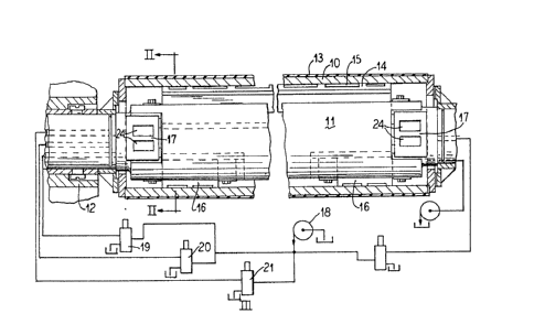
As illustrated in Fig. 1, a rotatable roll shell 10 is
supported on a stationary through shaft 11. The roll shell
coacts with an opposing member, not shown, to form a pressure nip
substantially at 13 and the nip is loaded by a unitary or a
plurality of axially extending shoes 14 which have oil
lubricating pressure pockets 15 therein facing the inner smooth
surface of the roll shell. The roll shell may be smooth polished
on the outer surface or may be co~ered with a rubber or other
compound.
At a lower location, that is 180 opposite the loading
shoes 14, are unloading shoes 16 which are located at the ends of
the roll shell. These shoes are supported on the stationary
shaft and are normally operated with light contact pressure
against the inner surface of the roll shell until such time as
the nip is to be unloaded at which time the shoes 16 are forced
downwardly to move the roll shell downwardly to unload and open
the nip. The shoes 16 are located at the ends of the roll shell
and are complementary to the loading shoes 14 and to the roll
shell in that they additionally help stabilize the roll shell at
operational speeds to avoid chattering and vibration. Also
aiding in the avoidance of chattering and vibration are lateral
end shoes 17 as shown in Figs. 1, 2, 4 and 5.
Fig. 2 additionally shows the unloading shoes 16 which
have oil pockets 22 therein. Lubricating oil is fed to the
pockets through throttling bores 23 extending up through the
center of supporting pistons 24 which are slidably mounted in
cylinders 25. Oil for pressurizing the sur~aces beneath the
13192~0
pistons 24 is supplied through an axial bore 26 extending through
the ends of the shaft.
Similarly, an oil pressure supply bore 20 extends
through the shaft to supply a ch~mber 17 beneath a piston 18
supporting the shoes 14. The shoes 14 have oil pockets which arè
supplied through throttling bores 16a extending up through the
pistons 18 and supplied oil from the chamber 17 beneath the
piston. Obviously, the oil pressure beneath the loading pistons
14, supplied through the bore 20 is substantially larger than the
pressure supplied through the bore 26, and as will be described
in connection with a feature of the invention, the oil for these
bores 20 and 26 as well as for the lubrication of the pockets in
the shoes is supplied from a common pump shown at 18 in Fig. 1.
This common pump also supplies the oil pressure and lubricating
oil for the lateral shoes 17.
The lateral shoes 17 are located essentially 90 from
the pressure shoes 14 and are located at each end of the roll
shell. The lateral shoes stablize and center the roll shell
relative to the shaft 11 and do so eliminating the need for
expensive bearings of the type which have heretofore been needed.
The shaft 11 is held stably at its ends by suitable
framework 12.
With reference to Figs. 4 and 5, the lateral shoes 17
are supplied with oil from a bore 49 through the shaft which
feeds out through lateral passages 4S to the individual lateral
shoes. The lateral shoes have pockets 24 in their outer faces
for lubricating the shoes relative to the smooth inner surface of
the roll shell 10. The pockets are supplied through throttling
bores 34 leading from a chamber 17a in the base of the shoe with
the chamber being supplied by the lateral passage 45.
-- 6 --
~3192~0
The shoes are uniquely vertically movable by being
slidable on smooth surfaces 48 at the sides of the shaft. An
elongate relieved portion 48a in the base of the shoe insures
constant communication with the lateral passage 45 as the shoes
slide up or down with shifting of the roll shell relative to the
shaft 11. Thus, the opposed lateral shoes 17 at each end of the
shaft center and stabilize the roll shell laterally and are self-
maintained in line with the axial center of the roll shell in
that they can slide up and down as the roll shell moves up and
down. The vertical position of the roll shell is, of course,
controlled by the force shoe 14 and the nip relieving shoe 16.
The lateral shoes are uniquely held in place and in turn
function to stabilize the axial position of the roll shell by
pads which face axial relative to the shaft. As shown in Fig. 5,
the roll shell has an annular ring 28 secured thereto. The axial
outer face of this ring has an annular lip seal 30 carried in a
ring 29 on the shaft and this lip seal 30 prevents the leakage of
a small amount of oil which may occur in the space inwardly of
the seal.
The inner face 42 of the ring 28 faces a circular oil
pocket 43 thereby allowing the roll shell to rotate and the oil
pocket 43 is supplied with pressurized oil through a passage 44
leading from the lateral passage 45. The la~eral shoe 17
encounters an axial force in the opposite direction from a pad 45
stationarily secured to the shaft. The pad 45 is circular and
seats in a circular pocket 46 on the lateral shoe. The circular
pocket 46 is pressurized through an oil passage 47 which
communicates with the chamber 17a fed by the passage 45.
Thus, the lateral pad 17 transmits a stabilizing axia
force to the roll shell from the shaft. The lateral pad is
~319290
supported axially to the left in Fig. 5 by the oil in the pocket
46 and the shoe 17 transmits this supporting force via the pocket
43 to the ring 42 on the roll shell 10. Thus, the lateral pads
17 provide not only a horizontal stabilizing force in the cross-
axis direction as may be viewed in Fig. 4 but also a horizontal
stabilizing force in the axial direction as viewed in Fig. 5.
Each of the lateral pads is of the same construction and operates
the same so that only the details of the pads shown in Fig. 5
have been described but it will be understood that the other
lateral pads are of the same construction and operate in the same
manner being fed through the axial passage 49.
Thus, all of the pressurized oil utilized by the
structure is fed from the common pump 18 which through pressure
control reducers 19, 20 and 21, Fig. 1, control the pressure
supplied to the various bGres including the bore 41 supplying the
pressure shoes, the bore 49 supplying the lateral pads, and the
bore 26 supplying the unloading shoes.
Figs. 6 through 8 illustrate other forms of stabilizing
and supporting the roll shell. In each of the figures, the roll
shell is shown at 10 with the respective figures showing through
shafts 50, 51 and 52 each of which have the self-loading shoes
14.
In the arrangement of Fig. 6, an unloading shoe 53 is
provided which extends over a substantial arc of the inner
surface of the roll shell 10 so that it provides lateral
stabilizing forces to the end of the roll shell as well as
unloading forces. ~his shoe 53 is located at each end of the
roll shell and is provided with bracketing arms 54 and 55 which
slidably engage outer surfaces 56 and 57 of the stationary shaft
50. This permits the shoe 53 to move up and down but holds the
. l3ls2~n
shoe in its lateral or horizontal position in a cross-axis
direction as viewed in Fig. 6.
The radial outward force for the shoe 53 is obtained by
oil pressure in a chamber 59 pressurizing the base of a piston
58. Throttling bores 61 lead from the chamber 59 to oil
lubrication pockets 60 in the outer circumferential face of the
shoe 53.
In the arrangement of Fig. 7, shoes 62 and 63 are
provided substantially 120 from the location of the self-loading
shoe 14. The shoes 62 and 63 are so located that they apply
force components which function to stabilize the ends of the roll
shell in a lateral direction as well as applying a nip unloading
force when pressurized.
The shoes 62 and 62 have pockets 64 and 65 in their face
which may be supplied with a separate source of oil, not shown,
or supplied up through passages in pistons 66 and 67 which
passages also are not shown. The shoes 62 and 63 are supported
on pistons 66 and 67 on axially extending roll pins 66a and
67a. For loading the shoes, chambers are located beneath the
pistons 66 and 67 supplied from a central oil pressure passage
68. This pressure can be dropped substantially to zero, and coil
compression springs 69 and 70 are located beneath each of the
pistons 66 and 67 to provide stabilizing forces to center the
roll shell during normal operation.
In the arrangement of Fig. 8, a first shoe 63 is located
substantially 120 from the pressure shoe 14 and this shoe can be
used for unloading the nip. The shoe has pockets 65 similar to
the shoes shown in Fig. 7 and has a supporting piston 67 with a
stabilizing spring 70 beneath the piston. A chamber beneath the
piston is supplied with oil from the supply line 68 to load the
piston for unloading the nip.
1319290
A lateral stabilizing shoe 71 is provided spaced 150
from the shoe 63 and 90 from the pressure shoe 14. This lateral
shoe 71 has pockets which are supplied with lubricating oil and
is supported on a roll pin 73 directly supported on the
stationary shaft 42.
Thus, in operation of the roll shell, referring to Figs.
1 through 5, the nip is loaded at 13 by the shoes 14 applying an
upward pressure to the inner surface of the roll shell 10 by the
chamber 19 beneath the pistons 18 being pressurized.
Unloading of the nip will be accomplished by
press~rizing the chamber 25 beneath the pistons 24 of the
unloading shoe 16.
Throughout the operation the ends of the roll shell are
stabilized and centered. The equipment which accomplishes this
function also dampens the roll vibration and prevents chatter
both in a radial direction as well as an axial direction of the
roll shell. This is accomplished by the lateral shoes 17 which
have lubricating pockets 24 and which are machined with a
dimension to fill the spaces laterally of the center stationary
shaft 11. The lateral shoes 17 are slidably mounted on vertical
faces 48 on the shaft. Axial forces are applied to the ends of
the roll shell by pressure in pockets 46 at the inner axial side
of the lateral shoes 17. This force is transmitted axially to
the roll shell by pockets 43 which are pressuri~ed with oil and
which face the smooth annular surface 42 of the annular ring 28.
Thus, it will be seen that I have provided a structure
which meets the advantages and objectives above set forth and
provides an improved controlled deflection roll such as used for
presses and calenders in paper machinery. The roll eliminates
the necessity for expensive bearings and the parts are
-- 10 --
131~29n
lubricated, supported and damped on hydraulic chambers or pads of
oil.