Note: Descriptions are shown in the official language in which they were submitted.
3L319~8
EYEGLASS FRAME
INCLUDING S~IAPE MEMORY ELEMENTS
FI ELD OF THE INVEN'rION
The present invention relates to frames for
eyeglasses and more particularly to frames fabricated from
materials which undergo phase transformation at given
temperatures or pursuant to stress and exhibit shape
memory properties, or pseudo-elastic properties, or a
combination of both.
TECHNOLOGIC~L CONTEXT
-
In the past, eyeglass frames have been
made ~rom metal or plastic. A combination metal and
plastic frame has also been disclosed.
In the prior art, shape memory metals have been
employed in the fabrication of eyeglass frames and related
components. S~ch metals have been suggested for use as
the rims of the glasses, as the fasteners for holding ~he
temples to the frame and for the temples.
Problems have arisen with the metals since there
are various phases or states of the metals martensitic9
austenitic and combinations of the two resulting in
characteristics such as superelasticity, two way shape
memory, rubber like behavior, austenitic to martensitic
transformation and the like.
In the martensitic state, the metals behave like
any memory metal in that the material can be deformed and
will hold this deformed shape, but upon heating will
revert to the memory shape. In the superelastic or
austenitic state, tne material is very elastic but exhib-
its no shape memory. In the combination state, the material
exhibits both properties. Specifically, if the strain on
the member is not more than 6% it will recover when re-
.. 1 ~
~31~8
leased. If the strain is in the ran~e of 8% or greater,it will take a set and not fully recover its original
shape.
It should be noted that state changes can be
induced by both temperature and strain effects. The
superelastic state is stress induced above the martensite
~to austenite transition temperature. In this mode, the
material is normally austenite but upon sufficient stress
reverts to martensite. When the stress is relaxed, the
material returns to the austenitic phase thus exhibiting
great springiness. If the strain exceeds approximately 8
the material acquires a permanent set.
Thus, the two states each provide desirable
properties but in certain specific environments such as in
eyeglass components as set forth in the present invention
not all requirements are met. Specifically, the elastic
state has no memory and thus can take a permanent set and
the memory state has no elasticity and can be recovered
only by heating. It has been a failure of the prior art
to apply the appropriate techniques and materials to the
appropriate eyeglass frame parts that has inhibited the
use of these types of materials in this fieldO
SUMMARY OF THE INVENTION
The present invention utilizes shape memory mater-
ials in specified areas of eyeglasses wherein the various
states of shape memory metals provide the desired
flexibility, shape memory or a combination of the two
characteristics of such materials. The invention also
contemplates shape memory materials in those instances
where flexibility is not required but strength and memory
are.
Instances of the latter are in frames which enclose
a portion edge of a lens about its periphery and thus grip
the lens inside of the edge and in shape memory rivets,
screws, or clamps for holding the temples to the main
frame. The alloys with memory and/or elasticity can be
used for temples, hinges for temples to frames and related
members.
~319~8
The alloys which exhibit both memory and
elasticity may be achieved by properly work hardening
martensitic alloys so that the material exhibits some
elasticity while retaining some shape memory. Thus, if
the component is deformed beyond its elasticity limit (but
still less than 8~) the deformation can be recovered via
shape memory. If on the other hand, the material exceeds
8~ strain, it takes a permanent set, but if it does not
exceed 10% strain, it acquires some springiness and can be
partially recovered at 10% strain back to 6% strain and a
combination material is produced.
Other material configurations may also be
employed. For instance, a combination of Nitinol and
spring stainless steel for holding the edge of the lens
can be designed that permits alternate opening or clamping
of the lens.
Shape memory metals according to this invention
include metals--such as nickel titanium alloys or Nitinol
and other martensitic transformation compositions that are
known such as the Cu-Zn-Al.
Shape memory metals are significantly distinct
from shape memory plastics in numerous respects. While
both can be plastically deformed from a memory configura-
tion and then recovered to the memory configuration by
directing them to a transition or recovery temperature
(e.g. by the application of heat), shape memory metals are
typically more endurant in repetitive deformation and
recovery cycling and can be selected to recover in small
temperature bands over a broad range of temperatures, e.g.
over 0K to 420K. Heat recoverable plastics on the other
hand feature (a~ less cost, and (b) recovery temperatures
typically above 100C. Metals are often used where plas-
tics would be inappropriate due to lack of strength or
corrosion resistance, or aesthetic values. In the present
invention, both shape memory metals and shape memory plas-
tics may he employed, although it is contemplated that the
characteristics of shape memory metals render them prefer-
able. Various members of eyeglass frames may be fabricated
from various of these materials. Where maximum shape
memory is required shape memory metals or plastic may be
employed. Where shape stability without memory but with a
high degree of resiliency is required Nitinol or like
materials in the superelasticity state may be employed,
such as in certain types of temples. Materials possessing
both elasticity and shape memory, i.e. combination mater-
ials, are useful in certain types of hinges, nose piece
supports and in some instances, in temples and front
pieces.
Hence, by employing shape memory material in
eyeglass frames new constructions (e.g comp~etely rimless
frames are possible and prior constructions are improved.
Faciliated fitting, certain fastening, effective
lens retaining, lower parts and production costs, and
enhanced appearance are achievable.
BRIEF DESCRIPTION OF THE DRAWINGS
Figure I is an illustration of a first embodiment
of the present invention.
Figure II is an illustration showing one
embodiment in cross-section of a lens retaining rim with
two-way action activated by heat.
Figure III is an illustration in cross-section of
another frame member and associated lens.
Figure IV is a graph illustrating YarioUs states
of martensite and austensite characteristics of materials.
Figure V is a general illustration showing a
temple pivotally coupled to a rim by a fastener.
Figures VI, VII, IX, and X are illustrations
showing various embodiments of shape memory fasteners
employable in coupling a temple to a rim as in Figure V.
Figure VIII is an illustration of the fastener of
Figure VII in the opened configuration.
Figure XI is an illustration of a fastener
employable in the embodiment of Figure X.
Figure XII is an illustration of a hinge
arrangement employing a shape memory nut and bolt.
- Figures XIII and XIV are front view and side view
illustrations, respectively, showing the coupling of nose
~3~9~
rests and temples to the lenses of the glasses.
Figure XV is an illustration showing a shape
memory rim which engages a lens and pivotally engages a
temple both upon heat recovery.
Figure X~ is an illustration of a support for a
nose piece for use in the present invention.
Figure XVII is an illustration of a one piece
hinge in accordance with the present invention, and
Figure XVIII illustrates a type of temple employed
in the present invention.
DESCRIPTION OF THE INVENTION
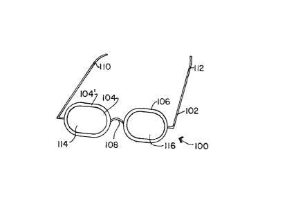
Referring to Figure I, eyeglasses 100 are shown
having a frame 102. The frame 102 includes two rims 104
and 106, a nose bridge 108, and temples 11~ and 112 which
extend from the rims 104 and 106, respectively. The
temples 110 and 112 extend back over the ears of a wearer
(not shown), the bridge 108 resting on the nose of the
wearer.
In Figure I, the rim 10~ is shown in a contracted
shape wherein the rim 104 abuts a lens 114 and forms a
tight fit therewith. The dashed representation 104' shown
in Figure I indicates a configuration of the rim 104 when
expanded outwardly relative to the lens 114. Rim 106 also
depicts an expanded rim relative to a lens 116.
The rims 104 and 106 are made of shape memory
material--such as, but not limited to, a martensitic
transformation metal (including a nickel titanium alloy
or Nitinol, various aluminum brasses, copper alloys, and
other known alloys)--or a heat recoverable plastic. In
this figure, by way of example, the shape memory materials
may be formed to have a memory configuration to which they
return when sufficient heat is generated therein. That
is, the shape memory material can be plastically deformed
and thereafter returns to its memory configuration when it
is heated. For metals, this memory characteristic is
attributed to changes of state in the metal or alloy
(between an austenitic state and a martensitic state, for
example) in response to heat being applied. The rim 104
~L3195L~8
or 106 can be plastically deformed and thereafter recov-
ered to a memory configuration by exposing the rim 104 or
106 to an appropriate temperature. The transition temper-
atures for shape memory materials are known in the arts
relating to metal shape memory materials and plastic shape
memory materials, respectively. The methods in which the
rims 104 and 106 are directed to a transition, or recov-
ery, temperature include: adjusting the temperature of the
environment surrounding the rims 104 and 106; passing
current through rims 104 and 106 tif metal) to generate
heat; inductive heating; or other temperature control
techniques. Preferably, a technique which permits close
control of the temperature of the rims 104 and 106 is
employed; e.g. dipping in water of proper temperature.
In one mode of operation, the rim 104 as shown in
solid representation in Figure I corresponds to the memory
configuration thereof. The dashed representation then
corresponds to a deformed state of the rim 104'. In the
deformed state, the rim 104' is sufficiently large to
enable the lens 114 to be inserted therein. ~pon heating,
the rim 104' contracts so that the inner surface thereof
120' comes into tight contact with the lens 114.
The speed at which the rim 104' contracts may be
closely controlled by controlling the application of heat
to the rim 104'. (This feature, it is noted, pertains to
all of the embodiments of the invention as relates to
recovery of the metals.)
By heating rim 106 according to this first
operational mode, the rim 106 will contract to retainably
engage the lens 116.
In another mode of operation, the rim 104 may be
in the deformed state when in the solid representation of
Figure I. By heating the rim 104 in this mode, the memory
configuration corresponding to representation 104'
results. Hence, in this mode, insertion and removal of a
lens 114 is performed when the rim 104' is the memory
configuration and the lens 114 is held in place by a
deformed rim 104.
Referring now to Figure II, a preferred cross-
section for a rim 200 according to the invention is shown~
~3~95~
The cross-section is C-shaped defining a channel 202 along
the length of the rim 200. The channel 202 has a radial
dimension which can be selectively increased or decreased
to enable release of a lens 204 or retention of the lens
204, respectively. As previously suggested, either
release or retention can be effectuated by recovery to the
memory configuration, the complementary operation being
performed by plastically deforming the radial dîmension of
the rim 200. Deformation may, if desired, be effected by
spring-loading which tends to reduce the channel radius--
the channel being increased in radius r with heating to
recovery temperatures.
In considering Figure II, it should be noted that
the lens 204 may be retained (a) solely or primarily by
the ridges 206 and 208 of the rim 200 or (b) by the ridges
206 and 208 together with a friction fit against the inner
surface 210 of the rim 200.
As shown in Figure II, the rim 200 includes an
inner layer 212 and an outer layer 214. The inner layer
212 is shown having the ridges 206 and 208 disposed
therealong, although the invention also contemplates
providing the retaining ridges along the outer layer 214.
(In this latter embodiment the C-shape circumferential,
ie. angular, dimension of the outer layer 214 would be
relatively greater than the circumferential dimension of
the inner layer 212). Similarly, engaging the lens 20~ by
both layers 212 and 214 is also contemplated. In any of
the above Figure II embodimentsl either the inner layer
212 or outer layer 214 may comprise a shape memory
material. The other layer is then, preferably, SST or
some other metal. When the outer layer 214 is shape
memory material, the rim 204 preferably closes upon
heating to engage the lens 204. When the inner layer 212
is shape memory material, the rim 204 opens to disengage
the lens 204 upon heating to the memory configuration.
Accordingly, by dipping rim 200 into hot water, the wearer
or practitioner is able to remove and replace the lens 204
which is engaged upon cooling. It should be recogni~ed
that the C-shaped cross-section may be provided in a
closed rim (e.g. see Figure I) or partial rim embodiment.
~319~48
Alternatively, it is noted, the rim 2~0 may comprise just
a single layer of shape memory material if desired.
In this latter case also, the lens configuration
of Figure III is preferred. In this case, material with
different characteristics, such asl different
transformation temperatures, stresses and the like, are
contemplated.
Referring to Figure III, there is illustrated in
cross-section a lens 301 having grooves 302 and 303 formed
in opposite sides of the lens about its periphery. A C-
shaped frame member 304 is disposed about the periphery of
the lens and has approved ends 305 and 306 seated in the
grooves 302 and 303, respectively.
A rim such as illustrated in Figure II may be
employed but preferably a rim of a single material having
shape memory is employed. Elasticity is not a major
factor in such an application but strength is and the
grooves permit a secure hold on the lens. In some
instances where elasticity as well as memory is desired,
material with combination characteristics (Cur~e F of
Figure 4) may be employed.
It should be realized that the C-shaped cross-
section of the rim 300 need not be circular as illustrated
but may be of smaller shapes which would function
similarly.
Reference is made to Figure IV of the accompanying
drawings which is a graph of various characteristics of
Nitinol which may be attained through various treatments
of the material. The materials represented by these
graphs have from about 49.9% to 51.5% Titanium by atomic
weight.
The graph A of Figure IV xepresents a material at
a temperature well above its transition temperature, i.e~
in the austenitic state. The material has no shape memory
but is quite strong and difficult to bend.
Curve B represents the superelasticity state. The
temperature of the material of Curve B is very close to its
transition temperatures but the material is in the
austenitic state. In this condition the material, so long
as it is not strained more than about 6% will follow Curve
1319~8
B; the material converting to martensite to relieve the
stress and upon release of the stress the material reverts
to austenite and resumes its original shape. The
materials represented by Curves A and B do not have shape
memory. If they are subject to a strain of over
approximately 8~, the material will not return to its
original state.
Referring now to Graph C, the material represented
by this curve is in the martensitic state and thus has
shape memory. If the material is stressed such that
strain does not exceed approximately 8~, the material will
reach point D on the curve and when the stress is
released, it will go to point F on the curve and
remain there until heated to a te~perature close to the
initial martensitic to austinite transition temperature.
Over the range o~ temperatures from the beginning of the
martensite transition to the temperature at which the
austenitic state is fully achieved, the material will
recover to its original shape; thus shape memory.
The Curve F represents a still further function of
the material. If the material is stressed along the Curve
C to a point G the material when released reverts to a
position H along the strain axis or abscissa indicating a
permanent set. If the composition of the material is such
that its transition temperature is about 50C and the
material has been work hardened and the material is now
heated above its transition temperature, the material will
assume a shape as represented by the point I on the strain
axis that is, the material will recover abouit 4% of the
strain to 6% strain. The material will thereafter follow
the F curve which represents the combination phenomena
previously discussed.
~31~8
Although only Nitinol has been discussed herein,
various changes in properties are affected by additives,
heat treatment and work hardening. Further, Cu-Zn-Al
and other copper-based and alike alloys are also specifi-
cally useful herein, having many of the same types of
characteristics as Nitinol. See, for instance, Shape
Memory Alloys, Page 728, Vol 20, of Kirk-Othmi's
Encyclopedia of Chemical Technology, John Wiley & Sons,
Third Edition. Still other materials exhibit some of
these same properties but are not currently economically
feasible.
Referring now to Figure V, the fastening of an
eyeglass frame temple 500 to an eyeglass frame rim 50~
with a fastener 504 is detailed. In Figure V, a shape
memory member 506 having a U-shaped cross-section is shown
extending from the rim 502. Inserted into the member 506
is an end portion 508 of the temple 500. A pivot element
510 enables the temple 500 and the member 506 to be
pivotally coupled when the member S06 is closed as shown
in Figure V. The member 506 is shown in its memory
configuration. In deforming the member 506 by spreading
its sides outwardly, at a cold temperature ~dry ice and
freon mixture, for instance) the temple 500 is
uncoupled from the member 506. The temple 500 can be
pivotally coupled by recovering the member 506 to the
memory configuration thereof. In such an embodiment, a
shape memory member is employed and recovered to the
initial position by heat which may be room temperature.
In Figure VI, a dual open-ended fast0ner 560 is
shown having an H-shaped cross-section--or two U-shaped
cross-sections. At each end is a transverse protrusion
562 extending inwardly from one side 524 of the fastener
560. The other side 566 of the fastener 560 is deformable
to open the space between the protrusions 562 and the side
566 and is recoverable by heating to a r0coYery
temperature. Fastener 560 may be used in an application
like that shown in Figure V.
The operation of the fastener 560 of Figure YI is
similar to that of the single open-ended fastener 570 of
~31~
Figures VII and VIII In Figure VII, the single open-
ended shape memory fastener 570 is closed. With the
temple end portion 572 inserted therein, a protrusion 574
extends through an aperture 576 in the temple end portion
572, thereby forming a pivotal coupling. In Figure VIII,
the fastener 570 is open to permit the insertion or
removal of the temple end portion 572.
In Figure VII-IX, the yoke or member 570 for
instance may be located on the temple and clamp a member
such as the end 572 on the main frame~ It is not intended
to limit the arrangement to a single pin such as pin 574
but a half pin may extend from each leg of the U or Yoke
and engage a hole such as 576 in member 572. Also, both
members, the temple and frame member, may be yokes with
opposed pins, or hemispheres, engaging opposed holes in
the other member.
Figure IX shows another type of fastener 580.
Rather than having a protrusion 674 on the U-shaped, shape
memory member 582 as in Figure VII, temple end portion 584
has two transverse male elements 586 which are receivable
by complementary female elements 588 in U-shaped member
582. As in the Figures VII and VIII embodiment, the
member 582 can similarly open and close to provide a
pivotal coupling.
In Figure X, pivotal coupling is achieved by
means of a shape memory stud or screw. The screw 590
screws or if a stud is pushed easily into apertures in a
temple end portion 592 and a U-shaped element 594 when
aligned. When recovered, the screw or stud 590 expands to
tightly engage the ~-shaped element 594.
If the element 590 is a stud, it takes the form of
the stud of Figure XI. The stud 590 has a head portion
1000 seated in a recess 1001 in the member 582. A split
shank 1002 extends from head 1000 through a hole 1003 in
member 594 and through aligned hole 1004 in the end member
592 of the temple. The end of the stud 590 has short
outwardly extending feet 1005 which catch on the top
surface of a shoulder 1006 in the bottom leg of the U-
shaped member 594.
When it is in its stressed state, the member 590
~3~9~8
slips readily through the aligned holes in the temple and
U-shaped member 594. When expanded the feet 1005 lock in
the recess 1006 and also engage the side walls of the
temple and lower U-shaped member to lock the members
together.
The edges of the feet 1006 may be compressed to
reset the stud and permit extraction. The heat
recoverable materials employed in the embodiments of
Figures V to XI are all of the shape memory type or of the
combination type so that particularly relative to Figures
X and XII, the studs or screws can be snapped into place.
As to the screw type, superelastic materials may also be
employed.
It will be noted that in the embodiments of
Fiyures IX and X, the stud or screw 590 is recessed in the
members to be joined so that no part of them can be
snagged or caught on adjacent ~bjects. As such there is
little likelihood of the stud or screw being compressed
and loosened or withdrawn.
In Figure XII a screw and nut assembly 600 is shown
for providing fastening through a lens 602 or to a temple.
As depicted therein, the screw 603 extends through a rim
604 and the lens 602 and is received by a complementary
nut 606. The screw 603 and/or the nut 606 comprise shape
memory material. When the screw 603 has shape memory, it
is preferably in a compressed state when inserted into the
nut 606. When the nut has shape memory, it is preferably
expanded when the screw 603 is inserted therein. When
recovered then, the screw 603 expands longitudinally
and/or the nut 606 contracts radially to effect tight
coupling therebetween. The magnitude of contraction
and/or expansion is readily controlled by the predefined
memory configuration of the screw 603 and/or nut 606.
These elements may also be recessed. The same concept may
be employed to produce a rimless design.
An alternative for the arrangement of Figure XII
is provided by the arrangement illustrated in Figures XIII
and XIV. Referring specifically to these Fiyures, rela-
tively small arcuate rim members are provided which clamp
the lens at the temples and at the nose piece~
1319~8
Specifically, shape memory members 1301 and 1302 are pre-
ferably squared C-shaped in cross-section and arcuate to
conform to the circumferential curvation of lens 1303 and
1305, respectively. The lenses are grooved preferably on
both faces to receive the ends of the C-shaped members;
grooves 1304 and 1306 providing a narrow projection 1307
extending from the lens 1303. The C-shaped member clamps
the projection 1307 and may be of the composite type
illustrated in Figure II or a combination type as illus-
trated by Curve F of Figure IV and this type of groove
arrangement may be employed in Figure III~ Such material
would be of particular use since elasticity is of value in
the event the glasses are struck and the nose piece is
bent. Strain which does not exceed 8% will not produce a
permanent set but if a permanent set is induced by a
strain of less than approximately 10% (a very large strain
in such an environment) the set can be recovered by
heating the members.
Referring again to Figure XIII, temples 1307 and
1308 are secured via hinges 1309 and 1310, to the lens
1303 and 1305, by members 1311 and 1312 which are sub-
stantially identical to members 1301 and 1302, except for
the hinge pieces. The method of connection to the lens is
also identical. The various members 1301, 1302, 1311 and
1312 are greatly enlarged in the drawings for purposes of
clarity of illustration but in reality provide a sub~
stantially rimless eyeglass of sturdy construction and yet
with the ability to readily replace defactive parts.
Figure XV shows an eyeglass frame 900 having
shape memory rims 902 and 904 which contract radially
inwardly when heated to a recovery temperature. As the
rims 902 and 904 decrease in radius upon recovery, lenses
906 and 908 inserted therein are engaged by the rims 902
and 904 and, also, temples 910 and 912 are pivotally
engaged. Specifically, protrusions 914, 916 and 918, 920
enter depressions or holes in the temples 910 and 912,
respectively.
Further in regard to Figure XV, it is noted that
the temples 910 and 912 may comprise stainless steel ~SST)
or some other metal when coupled to the rims 902 and 904
13
1319~L8
with a hinged joint as shown. Alternatively, the joint
may comprise a thin section of Nitinol which has good
flexibility and fatigue properties. That is, instead of a
multi-piece hinge, pivotal coupling may be achieved by a
foldable length of Nitinol disposed between each rim 902
or 904 and temples 910 and 912, respectively as
illustrated in Figure XVII.
Turning now to Figures XVI, nose rest 700 is
shown coupled to a rim 702 by an extension 704 of the rim
702. Each nose rest 700 may be tightly coupled to an
extension 704 by a shape memory fastener 706. The fasten-
er 706 is deformable from the memory configuration thereof
shown in Figure XV to open sufficiently to enable the
extension 704 to be inserted or removed. When recovered,
the fastener 706 encompasses and engages the extension
704. The material for these rests must be of the Curve F
type to permit both flexure over a limited range and
memory~
Referring more specifically to Figure XVII of the
accompanying drawings, there is illustrated a hinge for
the temple frame connection. In this modification, both
the end of 1400 o~ the temples 1401 and an extension 1402
from frame 1403 have deep recesses 1404 and 1405, respec-
tively.
A blade of Nitinol or like material treated to
have properties as represented by Curve F of Figure IV is
inserted in the recesses 1404 and 1405 and expanded to
tightly engage the sides of the recesses.
In this configuration the strain must not exceed
10% so that a permanent set is not imparted to the blade.
So long as this factor is observed, the elasticity from
the 6%-8~ strain is employed to maintain tension against
the side of the head of the wearer. If the blades are
strained between 8~ and 10%, the original shape may be
recovered by heat. In order to reduce the possibility of
excessive strain, the blade should be set at a 45 angle
so that the deflection from the set angle in either
direction is minimized.
The blades could also be riveted to the frame and
temple. The temples may also advantagously employ
14
~ 3 ~
Nitinol or like material but in this instance the material
is of the shape memory type and would be covered with a
soft plastic. Alternatively, a combination type material
may be employed in whish case the encasing plastic would
have to be a high temperature plastic to withstand the
me~ory recovery temperatures.
Referring now specifically to Figure XVIII, temple
1700 is composed of a U-shaped Nitinol or like member 1701
filled with a plastic insert 17n2 which contac~s the head
of the wearer. For extra strength the Nitinol member
could be an I beam or could have an outward decorative
ridge, such as ridge 1703 illustrated in dashed lines.
If such configuration is employed, the channel could be
eliminated and the whole temple covered in plastic.
Further, the channel 1701 could have return legs which
close about an SST insert to form an elastic member having
memory. If maximum shape memory is desired for the
temples, the material is martensite which is the weakest
state of the material. Thus in Figure XVIII the insert
1702 may be a thin blade of material which adds strength
to the structure but which is not strong enough to defeat
the memory effect of the memory material.
Other improvements, modifications and embodiments
will become apparent to one of ordinary skill in the art
upon review of this disclosure. Such improvements,
modifications and embodiments are considered to be within
the scope of this invention as defined by the following
claims. For example, it should, of course, be noted that
the rims as disclosed herein may, as an alternative to
being an independent rim, be a heat recoverable plastic or
metal wire or strip housed in a circular (or annular)
member surrounding the rim. And, moreover, various
coatings including plastics (of shape memory character or
not) and precious metals may be applied to the rims and
other elements of the frames as desired.