Note: Descriptions are shown in the official language in which they were submitted.
~ 3 ~-~
1 31 q56~
This invention is concerned with boats which are used for
scuba diving and related similar activities. In particular, this
invention is concerned with providin~ safe and simple water access
for persons involved in those activities.
Scuba diving and related other activities are commonly
practised in an underwater environment in relatively shallow waters
having a depth of generally less than 50 meters. Nevertheless, it is
not necessarily also the case that these activities are confined to
sheltered waters, as often places of interest to divers are in an
area of relatively open sea, which is subject to significant water
movement. At present, no steps appear to be taken ~o provide safe
and easy access for scuba divers to the water, even though the diver
may be encumbered with both protective clothing and breathing
equipment of significant weight, which also significantly hinders
movement out of the water. At present, the commonly used method to
enter the water is for the user wearing the equipment simply to fall
off a boat baclcwards into the water. Alternatively, the user may
jump off the boat into the water. To leave the water, the user
commonly still wearing all of the equipment simply clambers aboard
somehow, often assisted by others on the boat. Neither of these
procedures is either simple or particularly safe. For example, on
entering the water a diver has to take care to fall in baclcwards.
This invention seeks to provide a boat hull arrangement which
overcomes these difficulties, and which provides a safe and simple
means for a scuba diver to both enter and leave the water.
At various times various proposals have been made to
provide water access from boats of various types, including both
multiple hulls, so-called "moon pool'l hulls, and horseshoe shaped
hulls. Typical examples are as follows.
Coleman, US 4,267,851, discloses an underwater cruise device
comprising a diving chair mounted on a telescoping boom. The diver
does not leave the chair, with its life support systems, and can take
over command of the boat. A catamaran style hull is mentioned.
1 31 ~56q
Taylor, US 3,400,680, discloses a diving devlce conceptually similar
to Coleman, providing a submersible diving chair, with life support
systems, between the pontoons of a catamaran hull.
Creed, US 2,375,286, discloses a floating salvage platform using a
hull related to the modern SWATH-type. A sunken object, such as a
ship, can be retrieved from the sea floor and raised to a position
between the hull pontoon members.
Schlichthorst, US 4,702,18~, discloses a catamaran hull with an
overbridge including means, such as winches and the like, to raise
and lower ob;ects, such as a bathysphere or deep sea submersible,
from and into the water.
~cDermott & Co., West German 2,533,600 disclose a bouy retrieval
system wherein a special cage is lowered between the hulls of a
catamaran.
Flandin-Blety, France 2,583,707, discloses a diving chair9 operated
by a winch and pulley system, which is lowered beneath the hull of a
boat, and controlled by the diver working the winches. A diving bell
is provided for the diver's head; the diver does not leave the chair.
Tamura, Japan 60-56695, discloses a catamaran wherein a wave shock
absorbing member is provided under the bridge deck and which can be
lowered into the water when the vessel is stationary. The
construction of the member is such as to permit it when lowered into
the water to function as a sea-anchor and stabilise the ship, by
absorbing wave shocks. When the boat is in motion, the member
protects the undersurface of the main deck from wave impacts.
Freeland, US 3,034,155, discloses a twin pontoon swi~ming raft, with
a water access hole through its raft deck.
Popov, Russia 707,059, discloses a divers underwater hoist lowsrable
through the hull of a ship, for greater diver safety in rough seas.
1 3 1 9569
Kuo, US 4,312,287, discloses a ship having a moon pool which provides
a calm water surface. Within the moon pool, a retrievable float or
pontoon is provided, from which diving equipment can be separately
lowered. The float is raised out of the water when the ship is under
way. In use, the float is not connected to the ship.
Parsons, US ~,165,706, discloses a deep sea submersible vehicle
operation system utilizing a conventional hull with a central
deep-sea access aperture.
Ferris, US 3,503,357, discloses a ramp device which can be used as a
floating dock for seaplanes. The ramp can be retrieved out of the
water with an aircraft on it.
Storm, 11S 3,241,324, dlscloses a drill rig type platform, wherein a
submersible worklng surface is attached to a non-floating operating
stage.
Mayr, US 4,427,319, discloses an offshore construction in which a
floatable platform is supported by support legs which are directly or
indirectly on the sea floor. The support legs can be retracted to
move the complete unit.
Thus none of these proposals either address the peculiar
needs of those pursuing scuba diving and the like, nor do they appear
to be readlly adaptable thereto.
In its broadest aspect this invention provides a diving
platform, for use by scuba dlvers and the like~ comprising in
combination: a main deck means supported above water level by each
of at least two separate hull means;
a dlving deck means moveably positioned below the main deck,
means to move the diving deck from a first storage position, to a
second in-use position wherein at least part of the diving deck is
below water level and is between two separate hull members; and
1 3 1 9569
on-board access means between the diving deck in its second position
and the remainder of the boat.
Preferably, there are two hull means, and the boa~ is of
either the catamaran or SWATH type.
Preferably, the diving deck comprises a plurality of
panels, and wherein at least one of the separate panels, whilst
remaining attached to the remainder of the deck, can be moved
independantly relative to at least one of the other de~k panels.
Preferably, the diving deck is either lowered in a
substantially vertical direction from a substantially horizontal
storage position adjacent to the main deck, or is rotated about a
snbstantially horizontal axis from a substantially vertical storage
position on one of the hull means.
Preferably, the diving deck when in the second in-use
position is located at the most stable point of the ship between the
hulls.
The invention will now be described in more detail by way
of the attached schematic drawings in which:
Figure 1 shows a catamaran type hull, with the diving deck
stored;
Figure 2 shows a catamaran type hull, with the diving deck
lowered;
Figure 3 shows a SWATH or pontoon type hull~ with the
diving deck raised;
Figure 4 shows a SWATH or pontoon type hull, with the
- 4 -
1 31 9569
diving deck lowered;
Figure 5 is a partially sectioned view of Figure 4; and
Figure 6 shows in more detail a diving deck suitable for
the arrangements in Figures 1 through 5.
In these figures, like parts are given the same numbers.
In these figures, only the parts of the boat pertinent to
this invention are shown schematically. The remainder of the boat,
such as further decks, lifeboats, cabins, power plant and so for-th
are omitted for clarity.
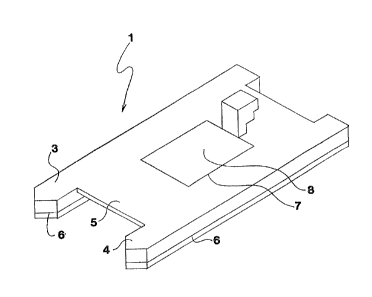
Referring first to Figure 1, a catamaran style hull is
shown generally at 1. This hull comprises a pair of hull members 3
and 4, ~oined together by a main bridging deck 5, which is situated
clear of the water line shown nominally at 6. In the center of the
main deck 5 is the diving deck, 7, which in this embodiment fits into
the aperture 8 in the main deck 5. As shown, the deck is in its
first storage position, with the access companionway shown
schematically at 9 also retracted.
In Figure 2A the same hull is shown generally at 1, with
the various other parts similarly numbered. However, the diving deck
7 is now lowered into its second in-use position below the main deck
aperture 8. The companionway 9 has also been moved into an extended
position and provides access to the lowered platform 7. As can be
seen from Figure 2B, which is a head-on view of the hull as in Figure
2A on a reduced scale, the deck 7 when lowered is below the water
level, as indicated by the water line 6.
In Figures 3, 4 and 5 an alternative SWATH-type hull
construction is shown. This includes two underwater pontoons 11 and
12, which support the main deck 5 by way of the vertical structures
13 and 14 which, together with the pontoons 11 and 12, are immersed
to the water line at 6. In Figure 3 the diving deck 15 is shown in
its first storage position, as also is the companion way 16. In
Figures 4 and 5 (which is a cutaway version of Figure 4) the diving
-- 5 --
1 31 9569
deck is shown in its second in-use position. Referring to Figure 4
first, the diving deck has been moved to its second in-use position
essentially by rotating it about an edge pivot essentially on the
axis 17. As this axis is below the water line 6, the deck when
rotated down is under water. After the diving deck has been moved
into the second diving posltion the companionway 16 is moved into
place to allow access to the diving deck.
There is one other difference between Figures 1 and 2 on
the one hand, and Figures 3, 4 and 5 on the other: the only aperture
needed in the main deck for Figures 3, 4 and 5 is that for the
companionway 16. In practise, the aperture 8 is not a necessity, as
the deck 7 can be retracted simply to be abutting to the underside of
the deck 5. Furthermore, if desired, access to either the deck 7 or
the deck 15 can be provided through the hull members themselves. The
disadvantage with using the hull members to provide access is that
apertures extending essentially below the water line 6 are needed,
which might pose problems of hull safety. Means to pump out any such
access areas would also be required to void them after use.
Nevertheless, it is contemplated as part of this invention
that the hull members be used for storage purposes for gear and
equip~ent needed by divers, especially the heavier items such as
breathing equipment. Rather than fitting on all of this equipment on
an above water open deck, with this invention a diver can fit on all
of his equipment in the water on the deck, in a calm area of
protected water, and then simply walk off the edge of the deck into
the water. In a similar fashion other gear such as outboard motor
powered inflatable boats can be stored in the hulls with direct
convenient access from the diving deck. With a deck of the type
discussed further below with reference to Figure 5, such a boat could
be launched simply by lowering a diving deck panel.
Turning now to Figure 5 in rather more detail, and to
Figure 6, in both cases the deck shown generally at 15 and at 18 can
-- 6 --
1 31 9569
be seen to comprise several smaller panels. In Figure 5 there are
three such (151, 152 and 153) where as in Figure 6 there are nine
(181 through 189); the unlt of Figure 6 is primarily intended to be
used with a hull arrangement as in Figures 1 and 2. The deck as a
whole ls raised and lowered by hydraulic struts shown schematically
at 19; similarly, hydraulic means are used to move the various
panels. The details of this system are omitted for clarity. ~n
interlock system would be desirable in the system, to prevent the
deck 18 being fully retracted if any of the panels 181 through 189
are not in a flat configuration, although it is desirable to be able
to move the deck to change its immersion depth without having to move
all of the panels first.
In Figure 5 the deck is three components (which agaln are
conveniently moved hydraulically) 151, 152 and 153 which in their
turn are attached to the panel 154. The panel 154 is attached to the
hull member 14, and rotates essentially along the axis 17 to return
the whole diving deck to its first storage position. Each of the
panels 151, 152 and 153 separately can also be moved relative to the
panel 154 essentially on the axis 155. Thus as shown hatched, panels
152 and 153 could be lowered to provide an easy access slope into the
water, or to provide boat launching facilities.
The diving deck shown in Figure 6 is rather more
complicated. The only panel not capable of being moved
independantly, if so desired, is the central one, 189. But even this
can be angled, as the four hydraulic legs 19 can be independantly
controlled. In theory, any of the outer panels 181 - 188 could be
moved independantly of each of its neighbours, as indicated for
panel 181. In practice more limited movement as shown for panels
183, 184 and 185 would suffice for most purposes. For example, the
middle three panels 182, 189 and 186 could be located level,
athwartship, with some of the fore and aft panels 183 - 185 and 181,
188 and 187 lowered to provide a water walk-in ramp and a boat dock.
1 31 956q
In the preceeding description, a catamaran or slmilar hull
with only two hull members is considered. This is the preferred
arrangement, since the deck can be placed at the most stable point.
If the boat is then moored with due consideration of currents and
wave conditions, a very calm water area can be obtained between the
hull members. Further, where a shallow reef, for example, is to be
investigated, the deck can be lowered until it is in contact with the
reef surface. The deck of this invention could be used wi-th a
trimaran or similar hull, but then there is the disadvantage that the
central flotation member will obstruct the deck being placed at the
most stable point, which is the most preferred location for the deck.
Similarly, only one companionway (e.g. 9 in Figures 1 and 2) has been
shown: more than one might be found convenient. Alternatively, a
lift or elevator means could be used to provide access to the diving
deck.
-- 8 --