Note: Descriptions are shown in the official language in which they were submitted.
1 3 1 q575
Improvements to hot water production appliances
The invention relates to h~t water production
appliances such as water heaters, bath heaters, central
5 heating boilers,...
It relates more particularly, among these appliances,to
those comprising a burner fed with pressurized fuel gas
and combustive air and a heat exchanger itself formed of a
water conduit extending from an inlet for the water to be
10 heated as far as an outlet for the heated water and a
"gas" circuit comprising a combustive air intake section
and a guide section for the combustion gases, in which
these gases are led on to the water conduit so as to yield
up thereto their heat before being discharged cooled.
The object of the invention is especially to improve
the appliances of the kind in question, particularly in so
far as the eff.iciency of the heat exchange is concerned -
which makes it possible to reduce the size and weight of
the appliance for a given heating power -, simplicity
20 of manufacture and long life.
For this, the hot water production appliances of the
kind in question according to the invention are
essentially characterized in that their water conduit is
formed by a nest of rectilinear, identical and parallel
25 tubes spaced apart in a cylindrical annulus wi~h vertical
axis and each extending between two coaxial rings, in tha-t
the combustive air intake section comprises an annular
jacket surrounding the nest of tubes, in that the
combustion gas guide section comprises an intermediate
30 annular sleeve through which the ne$t of tubes passes, the
base of which sleeve is connected to the base of a central
discharge chimney open at the -top and in that the burner
extends annularly, at the upper inlet of the annular
sleeve, about the upper portion of the chi~ney and is
35 adapted so that the flames generated thereby are oriented
downwards.
1 31 9575
- 2 -
In preferred embodiments, recourse is further had to
one and/or other of the following.arrangemen-ts :
- the heat exchanger of the appliance comprises two
independent water conduits assigned respectively to the
5 sanitary water and to the heating water, each conduit
comprising a portion of each rectilinear tube and a
portion of each ring, each ring portion of a given conduit
being connected sealingly exclusively to the tube portions
corresponding to this conduit, and the rings are
10 partitioned on the inside so as to break up the assembly
of the n tube portions of each conduit into p contiguous
banks each comprising n/p tube portions, p being an even
number, preferably equal to 6 or 8, so that the water flow
through the contiguous banks takes place alternately
15 upwards and downwards,
- in an applia~ce according to the preceding paragraph,
the rectilinear tubes are double tubes comprising a first
tube with elliptic cross section with the large axis of
the ellipsis extending radially with respect to the axis
20 of the appliance and a second tube with circular cross
section housed jointingly in the central zone of the first
tube,, the portion of each double tube thus formed
assigned to the sanitary water being the volume inside the
inner tube and the remaining portion of the inside volume
25 of the first tube being assigned to the heating water,
- the appliance is provided, in the vicinity of the
"downstream" faces of the tubes, i.e. the faces of these
tubes situated on the hot gas outlet side, with deflectors
profiled so as to increase the heat exchange between these
30 gases and these downstream faces,
- the appliance comprises baffles disposed across the
intermediate sleeve so as to improve the heat exchange
between the hot gases and the tubes,
- the intermediate annular sleeve comprises an upper
35 widene~ portion forming an annular combustion chamberj
- the whole of the intake of combustive air through the
1 31 q575
-- 3 --
annular jacket is fed into the intermediate annular sleeve
through orifices of the burner, in the centre of which
orifices the fuel gas is admitted,
- the grid in which the orifices of the annular burner are
5 formed is situated at the level of the top of the upper
ring forming part of the water conduit,
- the connection zone between the base of the intermediate
annular sleeve and the base of the chimney is defined at
the bottom by an inclined wall adapted to collect the
10 condensates and connected to a lower discharge connection.
Apart from these main arrangements, the invention
comprises certain other arrangements which are preferably
used at the same time and which will be more explicitly
discussed hereafter.
In what follows, two embodiments of the invention will
be described with reference to the accompanying drawings
in a way which is of course in no wise limitative.
Figures 1 and 2 of these drawings show respectively in
axial vertical section through I - I of figure 2 and in
20 horizontal cross section through II-II of figure 1, a hot
water production appliance formed in accordance with the
invention;
Figure 3 shows, similarly to figure 1 but a little more
schematically, a variant of such an appliance, also in
25 accordance with the invention;
Figures ~ and 5 are diagrams relative to the water flow
in the appliance of figure 3.
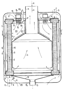
The appliance shown in figures 1 and 2 has the general
form of a cylinder of revolution with vertical axis X.
It comprises a conduit for the water to be heated, a
gas burner fed with a pressurized fuel gas and a circuit
for the gases, which are formed upstream by the combustive
air and, downstream, or more precisely from the burner
level, where the combustive air is mixed with the fuel gas
35 so as to form the heating flames, by the combus-i~ion gases.
The water conduit comprises :
1 31 ~575
-- 4 --
- a "barrel" or nest of parallel, rectilinear and
identical tubes 1 extending in a cyllndrical annulus with
- axis X between a lower ring 2 and an upper ring 3,
- a cold water intake pipe 4 connected to the lower ring 2
5 at a point A,
- and a heated water discharge pipe 5 connected to the
upper ring 3 at a point B.
The connection points A and B are disposed at
positions, in rings 2 and 3, such that each drop of water
10 to be heated is forced to pass through not only one of
tubes 1, in the barrel, but also at least half of the
circular extent of a ring 2 or 3.
For this it is advantageous to provide in each of these
rings a radial dividing wall 6 preventing the water from
15 taking too short a path : preferably, two such dividing
walls 6 are disposed respectively in the two rings 2 and 3
in two superimposed zones in the same vertical plane, the
lower intake point A then being placed on one side of this
plane and point B, on the other side.
The cross section of each tube 1 preferably has the
form of an ellipsis whose large axis extends radially with
respect to axis X : the adoption of such a shape has the
double advantage of conferring on the tubes a good
resistance to deformation and providing a good heat
25 exchange coefficient between the -tubes and the gas flowing
between these tubes.
The upstream portion of the gas circuit comprises an
external cylindrical ~acket 7 with double wall which
envelops the nest of tubes 1.
This jacket is defined externally by ~he peripheral
lateral portion 81 of the protective cover 8 of the
appliance.
This cover 8 also comprises two flat horizontal
portions 82 and 83 extending the side portion 81 at the
35 bottom and at the top and forming the bottom and roof of
the appliance.
1 ~1 9575
-- 5 --
Bottom 82 is formed with an oriice 25 communicating
with the free air, which orlflce forms the combustive air
intake opening in jacket 7.
The downstream portion of the gas circuit comprises :
5 - an intermediate sleeve 9 which is disposed inside jacket
7 and through which the tubes 1 pass,
- a central chimney 10 whose base is connected to the base
of sleeve 9 and whose uppex portion, in the orm of a
cylindrical and narrowed neck 11, is connected towards the
10 top to an external discharge pipe.
The common connection base between sleeve 9 and chimney
10 is defined towards the bottom by an inclined wall 12 in
the shape of a funnel adapted for collecting the
condensates and discharging them into a cen-tral lower
15 discharge connection 13.
Burner 14 has an annular shape surrounding neck 11 and
it is adapted so as to produce downwardly orien-ted flames
15.
More precisely, it comprises here a feeder 16 supplied
20 with pressurized fuel gas and connected to a plurality of
distribution needles 17 which open at the centres of
apertures 18 formed in a wall l9.
This apertured wall 19 has the general shape of a flat
hori~ontal washer connecting neck 11 transversely to ring
25 3-
Each aperture 18 is therefore fed at its centre with
fuel gas and for the rest of its cross section with
combustive air coming from jacket 7.
The different dimensions and configurations of needles
30 17 and holes 18 are chosen so that the combustive air-fuel
gas mi~ture pro;ected downwards through each aper~ure 18
has a composition leading to good combustion (slight air
excess~.
A burner of this type has been described in the patent
35 application France 88 03618 of the Applicant.
The annular combustion chamber 20 in which the
5 7 5
-- 6 --
downwardly directed flames 15 are formed is the upper
widened zone of sleeve 19, surr~unding the base of the
neck of chimney 11.
~o as to avold too yreat a transfer of the hea~
5 generated in this chamber towards neck 11, the wall which
separates this neck f~om this chamber is lined with a
refractory and heat insulating lagging 21, which wall has
a cylindrical upper section and a downward divergent
truncated cone shaped lower section.
Therecan be further seen in the drawings :
- an ignition electrode 22,
- a flame detector 23 situated in a position diametrically
opposite igniter 22 with respect to axis X,
- and an annular seal 24 inserted between funnel 12 and
15 the lower ring 2.
The different elements forming the water condui-t and
the gas circuit of the appliance are advantageously formed
by thin stamped stainless steel sheets which are crimped
or welded together.
The operation of the appliance described above i5 the
following.
It is assumed that this operation corresponds to normal
operating conditions, after ignition of the burner : such
ignition is controlled in a way known per se, either by
25 the water flow through the conduit 1-5 or by exceeding a
tempera-ture threshold. This control results in the opening
of a supply valve of the fuel gas feeder 16, ignition of
the air-gas mixture then delivered through apertures 18
being provided by sparks coming from igniter 22 with
30 control by detector 23.
The water to be heated flows in the ~irection of arrows
E.
It is admitted through pipe 4 in the lower ring 2.
From there it rises through tubes 1 as far as ring 3,
35 then, heated, it leaves the appliance through pipe 5~
Considering the identity of the pressure losses
1319575
-- 7 --
underyone by ~he water in all the parallel circuits likely
to be taken by this water, the- water flow is divid~d
identically between all the tubes 1 and the volume of
water in circulation rises then simultaneously through all
5 these tubes.
The gases flow in the direction of arrows G.
The ambient air is firstly introduced at the base of
the appliance at 25 and is heated by a few degrees when
rising through jacket 7, after which it reaches the upper
10 ring 3 and changes dirsction and descends to the level of
the burner.
It is then ejected through apertures 18, where it joins
up with the central fuel gas jets leaving the needles 17.
The combustion of the air-gas mixtu~e thus pro;ected
15 generates flames 15 in the combustion chamber 20.
The very hot combustion gases from this chamber 20 then
flow along tubes 1 and surround these tubes in a downward
flow.
At the base of these -tubes, the cooled gases pass along
20 the lower ring 2 before once more changing direction and
escape upwards through the central chimney 10-11.
In the hot water production appliance shown in figures
3 to 5, we find a number of the features which have been
described above in connection with the appliance of
25 figures 1 and 2 and the corresponding elements are shown
in the drawings with the same references as before.
This new appliance differs from the preceding one by
the different points described hereafter.
Instead of being admitted at the base of the
30 cylindrical external jacket 7, the combustive air is this
time admitted into this ~acket through its top, through a
neck 26 surrounding the top portion 11 of the central
chimney, with clearance, said neck extending the lid 83 of
the cover upwards.
The air in question then flows from top to bottom
through said jacket 7, it is taken up ~t the base of this
1 31 957~
~acket, through a hole formed in the centre of bottom 82,
by a fan 27 disposed below this hole, then it is driven
throuyh a pipe 23 above the annular burner 14.
Bottom 29, intended to collect the condensates, is here
5 again conical, but it has this time its tip pointing
upwards and not downwards and the condensates collected
are discharged throu~h an off-centred opening 30.
Instead of being distributed at the top and hottom o~
the appliance, all the connections for the water and for
10 the fuel gas are here disposed at the base of the
appliance, which facilitates mounting and dismantling.
Instead of being formed by an appliance ~ith a single
water circuit of the water heater type, the appliance
considered here is a combined boiler for providing at one
15 and the same time central heating by hot water flow
through radiators and heating of the sanitary water.
For this~ its exchanger comprises two independent water
conduits each comprising a portion of each water tube 1
and a portion of each ring 2, 3.
More precisely, each tube ~ is here a double tube
formed of a first tube 11 with elliptic section of the
kind described above and the second tube 12 with circul.ar
section housed jointingly inside the central zone of tube
ll .
The inner volume of each double tube thus defined may
then be considered as formed of two portions, one s inside
the central circular tube 12, reserved for the flow of
sanitary water and the other c reserved for flow of the
heating water and comprising the two remaining volumes
30 disposed on each side of the central tube 12, inside the
elliptic tube 11. .
Further, each ring 2, 3 is here a double ring formed of
two elementary rings or annular halves superimposed
vertically one on the other and each conduit comprises a
35 half of each double ring, alone connected sealingly to the
tube portions s or c concerned.
1319575
In what follows the index s relates to the sanitary
water circuit and the index c to the heating water
circuit.
Thus, in the embodiment illustrated, ~he lower half 2s
5 of the lower ring 2 and the upper half 3s of the upper
ring 3 are assigned to the sanltary water whereas the
other two ring halves 2c and 3c are assigned to the
heating water.
Furthermore, each cylindrical annulus of n tube
10 portions s or c is broken down into p successive banks of
such tube portlons, which banks are defined as follows :
- p is an even number, preferably equal to 6 or 8,
- the water flows in the same upward or downward direction
through all the tube portions of the same bank,
15 - the water flows in two opposite directions in the banks
which are contiguous two by two.
To obtain such an arrangement, each of the elementary
rings is divided circumferentially, by diametrical
dividing walls 31, 32, of the same kind as dividing wall 6
20 above, into p/2 successive identical sections, the
respective posi~ions of dividing walls 31 in the lower
ring being offset angularly by 360/p about the axis of
the appliance with respect to those of dividing wal~ 32 in
the upper ring.
With such a distribution, shown in figure 4 for the
sanitary wa~er, the cold or relatively cold water admitted
at the upstream bottom end 33s of a bank follows first of
all a section of the lower ring 2s, then rises through the
n/p parallel tube portions s of the first bank as far as
30 the corresponding upper ring 3s~ then it flows through a
section of this upper ring before flowing down again
through the parallel tube por-tions o the second bank, and
so on, the heated water arriving at the end of the path
being finally discharged at the downstream bottom end 34s
35 of the last bank of rank p.
This sinuous flow of the water, by successive alternate
1 3 1 q575
-- 10 --
upwards and downward passes, has, over the flow pat-ter~
shown in figure 1, the advantage of a greater speed, this
speed being multiplied by the coef f icien~ p, which
prevents the formation of limit layers on the tubes and so
5 improves the heat transfer coefficient between the hot
gases and these tubes.
In an embodiment which has given every
satisfaction, the values adopted respectively for
parameters n and p were 56 and 8, each bank comprising
10 then 7 tubes.
Each of the two sanitary water and heating water flows
is organized as in the above described sinuous
arrangement.
Since these two flows are independent, their respective
15 directions can be chosen at will as well as the angular
positions for intake of cold or relatively cold water and
discharge of hot water and even the number of tube
portions included in each bank.
For example, as in the case of figure 5, the following
20 may be chosen :
- identical numbers p for the two circuits,
- opposits flow directions for the water through these
circuits, the water then flowing contraflow wise through
said circuits,
25 - diametrically opposite angular positions in the
cylindrical annulus formed by the different tubes for the
intakes corresponding to the two circuits as well as for
discharge thereof,
- and identical angular positions in twos for the
30 separating walls - such as 31s and 31c, or 3? S and 32C
corresponding respectively to the two sanitary water
drawing and heating water circuits and belonging to the
same double ring 2 or 3, except of course for the end
dividing walls.
In a way known per se, in order to improv~ the
efficiency of the heat exchanges, means are provided for
1 31 9575
causing the heatin~ water to flow in the correspondiny
circuit whenever sanitary water i5 drawn off.
To improve the heat exchange between tAe hot gases and
the tubes, recourse is further had advantageously to
5 baffles and/or deflectors adapted for deflecting the
stream of said gases appropriately.
The baffles are advantageously two metal discs 35, 36
mounted in the inner sleeve 9 and apertured so that the
tubes can pass therethrough; one of thsse discs 35, the
10 upper one, is carried by the dividing wall defining the
central chimney 10 so as to drive the gases radially
outwardly whereas the other disc 36, the lower one, is
carried by the dividing wall defining inwardly the
external jacket 7 so as to drive the gases radially
15 inwardly, these gases being again driven radially
outwardly at the bottom of sleeve 9 so as to pass round
the lower ring 2.
The deflectors are formed by profiled screens 37
(figure 2) disposed in the vicinity of the "downstream"
20 faces of the tubes, i.e. the faces of these tubes disposed
on the same side as the outlet of th~ hot gases passing
radially between said tubes.
The profile of these screens 37 is provided so as to
send said gases against said downstream faces and increase
25 their flow speed.
Furthermore, apertures 371 are formed in said screens
so as to form passages ~or the gases.
Deflectors 37 may be mounted on baffles 36 and bear
laterally against the tubes.
They may also be limited to their curved portions alone
included between the tubes, which portions are connec-ted
together by continuous strips at least in the vicinity of
their axial ends.
In figure 3 can be seen, gathered together at the
35 bottom of the appliance :
- the connections 33s~ 33c~ 34s and 34c corresponding
1 3 1 9575
- 12 -
respectively ~o the sanitary water and heating water
inlets and to the sanitary water and heating water
outlets,
- a connection 38 extending the condensate discharge
5 orifice 30 downwards,
- and a pipe 39 for intake of the fuel gas into feeder 16
through a regulation member 40.
Following which, and whatever the embodiment adopted, a
hot water production appliance is finally obtained whose
10 construction and operation are sufficien~ly clear from the
foregoing.
This appliance has numerous advantages with respect to
those known heretofore and especially ths following :
- the heat exchange efficiency is very high,
15 - manufacture of the appliance is particularly simple,
- and it has remarkable strength and long life, as well as
reduced size.
As is evident and as it follows moreover from what has
gone before, the invention is in no wise limited to those
20 of its modes of application and embodiments which have
been more especially considered; it embraces, on the
contrary, all variants thereof.