Note: Descriptions are shown in the official language in which they were submitted.
s~ ~3 C'~
BACKGROUND OF THE INVENTION
The present invention relates to a method of pro-
ducing halopolymeric films, such as and particularly
fluoropolymer films, at high productivity and to
halopolymeric films produced using the method.
--1--
13~ 9~3
The production of thin plastic films has generally
been accomplished using one or more of three processes:
melt extrusion, casting from solutions or organosols, and
casting from aqueous dispersions. Melt extrusion of films
is generally preferred to casting since it does not require
the removal of an organic solvent, water, or surfactants.
It therefore produces a very clean film and typically is
characterized by high productivity. Melt extrusion cannot,
however, be used for all materials.
Casting methods are preferred if the required time
at extrusion temperature is sufficient to result in thermal
or oxidative degradation of the polymer. Casting is also
preferred when the melt viscosity of the polymer is suffi-
ciently high to make extrusion either technically impossible
or economically impractical.
In the case of fluoroplastics, all three processes
are used to produce films, with the choice of process large-
ly depending on the monomer content of the polymer. The
most common monomers presently employed to produce 1uoro-
plastics include tetrafluoroethylene (TFE), chlorotrifluoro-
ethylene (CTFE), vinylidene fluoride (VF2), and vinyl fluo-
ride (VF). All of these are available as homopolymers;
* *
i.e., PTFE (e.q., "Teflon"), PCTFE (e.q., "Xel-F"), PVF2
* *
(e.q., "Kynar"), and PVF (e.q., "Tedlar"), respectively.
* Trade ~ark
131~3~3
PCTFE and PVF2 are melt extrudeable as thin films with some
difficulty due to the fact that the time/temperature history
during extrusion is near to that which could result in poly-
mer degradation at the severe shear rate of melt extrusion.
This condition can be further aggravated in the presence of
certain fillers. PVF film cannot be produced by melt ex-
trusion due to thermal instability and thus is produced by a
casting process and subsequently is biaxially stretched.
Homopolymer PTFE cannot be practically melt extruded at all
due to its extraordinarily high melt viscosity.
In order to overcome such problems in the case of
melt extrusion of these homopolymers, copolymers of these
monomers have been developed which are generally lower in
melting temperature and melt viscosity at extrusion tempera-
tures. This allows extrusion of the polymers at tempera-
tures at which no significant thermal degradation occurs.
Consequently, fluoropolymer films are most generally based
upon such readily extrudeable copolymers. These include
copolymers of TFE with hexafluoropropylene, e.q., "Teflon"
FEP, or with perfluoroalkyl vinyl ethers, e.q., "Teflon"
PFA, or with ethylene, e.q., "Tefzel" ETFE. Similarly,
copolymers of CTFE include those with vinylidene fluoride or
hexafluoropropylene, e.q., "Xynar", as well as with ethy-
* Trade Mark
131~ r~ 3
lene, e.~., "Halar" . Terpolymers of these basic monomersare also known and used in extrusion.
Since pure PTFE cannot be melt extruded, as
mentioned above, other processes have been developed for
film production. One such method involves the skiving of
thin film from a molded and sintered billet. Another
involves the casting of an aqueous dispersion onto a
metallic carrier. The deposited resin is subsequently
stripped from the carrier to yield a very high quality film
relative to the skived films.
A casting process for PTFE is described in U.S.
Patent No. 2,852,811 issued to John V. Petriello in 1958.
In summary, this process involves continuously depositing a
layer of a PTFE dispersion onto a metal carrier, drying the
coated carrier and then sintering the dried coating. These
steps are then repeated until a film of the desired
thickness had been formed. The film is then stripped from
the carrier. U.S. Patent No. 2,852,811 stresses the
importance of the nature of the carrier belt used in the
casting process. Thus, highly polished, corrosion resistant
metal carrier belts have been used in subsequent casting
efforts.
Cast PTFE films exhibit virtually no mechanical
anisotropy, and have substantially higher tensile strength,
* Trade Mark
~ 3 ~
elongation, and dielectric breakdown strength than skived
PTFE films. Unfavorable process economics, however, have
prevented a wide acceptance of casting as a method for mak-
ing fluoropolymer films. Among the factors affecting the
economics are the properties of the metal carrier belts.
These belts are fairly rigid and heavy, and thus require a
special tracking mechanism to drive the belt through the
apparatus. This essentially fixes the width of the material
produced, causing a loss in versatility.
The casting process as described by Petriello also
suffers as a result of low productivity. In an effort to
elaborate upon the significant process parameters affecting
film quality, investigations were sponsored by the Aero-
nautical Systems Division of the United States Air Force
between 1955 and 1962 which resulted in the publication of a
report entitled "Production Refinement of Very Thin Teflon
Film." This publication emphasized the importance of the
dispersion characteristics and line speed as each can sig-
nificantly affect the quality of the cast film. Specifical-
ly, the Air Force study observed that the quality of film
produced by the casting method deteriorates very rapidly at
line speeds above 3 feet per minute. (See p. 19 "Production
of Very Thin Teflon Film"). Productivity of film manufac-
ture at such slow rates is in general prohibitively costly:
~3~Ln~9~
even simple, monolithic cast films of PTFE must be sold at
four to five times the price of skived PTFE or two to three
times that of extruded FEP to be economically attractive.
This has led to very minimal acceptance of cast films in the
marketplace and has been the major cause of the lack of
continued research over the past decades into processes for
casting fluoropolymer films.
Additionally, the very low critical cracking
thic~ness of most fluoropolymer dispersions suggest that
thicker individual lamellae within any given film cannot be
achieved to even partially offset the poor productivity
associated with the very low linear line speed.
It is of interest to note, however, that all of
the previously mentioned fluoroplastic homopolymers and
copolymers are available as aqueous dispersions and can be
used to produce cast films. ~oreover, the casting process
potentially offers several distinct advantages over the
extrusion process for producing films. The casting process
inherently is a multi-layering process; thus, multi-layer
film production by casting methods avoids the intrinsic
problems and substantial unit investment which would be
associated with coextrusion or extrusion coating of fluoro-
polymers. PTFE films with surface(s) of fluorinated ethy-
lene propylene (FEP) or perfluoroalkoxy resins (PFA) are
--6--
131~3~3
available commercially from casting equipment.
Additionally, the casting of alloyed fluoropolymers,
including both thermoplastic and elastomeric polymers and
which may optionally incorporate metal, mineral, or ceramic
additives to modulate chemical, optical, electrical, and
magnetic transport properties of film is facilitated by the
casting process in both monolithic (uniform composition) and
complex (non-uniform composition) film format. Such films
are described in commonly assigned U.S. Patents Nos.
4,770,927; 4,555,543 and 4,610,91g and Canadian Patent No.
1,262,676. Most importantly, such a process permits one to
combine in a single layer, or in sequential layers, polymers
with widely different melting temperatures and degradation
temperatures since the time/temperature history of the film
as it is processed can b~ kept much shorter than that
characteristic of melt extrusion.
In short, the casting process is an inherently much
more powerful method than the extrusion process for
producing high quality films with a far larger number of
compositional degrees of freedom. It is an object of the
present invention to provide a method for the production of
halopolymeric films, such as fluoropolymer films, in which
the relationship between productivity and film quality is
- - - 1 3 ~ 3 ;
dramatically altered such that one can economically take
advantage of this superiority. The products of this process
could enjoy significant use in electrical and electronic
applications as well as in selective membranes and other
chemical applications.
Summary of the Invention
This object is achieved in accordance with the
invention using a method for preparation of a halopolymeric
film, including most preferably a fluoropolymeric film, on a
carrier, comprising:
(a) preparing an a~ueous dispersion comprising a
halopolymer which may preferably include a wetting
surfactant in a minimum amount effective to facilitate
wetting of the carrier belt by aqueous dispersion
techniques;
(b) coating, such as by dipping, a carrier belt
through the dispersion such that a coating of the
dispersion is formed on the carrier belt;
(c) moving the coated carrier belt through a
metering zone to remove excess dispersion, which zone
may preferably be a bath of the dispersion maintained
at a temperature below that which would result in
coagulation of the polymers at the metering surface;
13~r~ 3
(d) drying the metered coated carrier to remove
the water from the dispersion;
(e) heating the dried coated carrier belt to a
temperature sufficient to at least substantially
eliminate surfactants in the dispersion;
(f) further heating the carrier belt to a
temperature to melt or (depending upon the polymer) to
soften the halopolymer;
(g) cooling the polymer-coated carrier belt to
consolidate the coated polymer; and
(h) stripping the consolidated halopolymeric film
from the carrier belt.
The carrier belt is characterized by
possessing low thermal mass having chemical and
dimensional stability at the softening or melting
temperature of the halopolymer and is further
characterized by being uniformly wettable by the first
dispersion applied and exhibiting a wor~ of adhesion to
the consolidated polymer coating that does not exceed
the peel strength of the consolidated polymeric film.
Thus, the method of the present invention defines
a film casting process which differs from that of the prior
art in at least two critical aspects -- the use of metering
equipment to define the amount of halopolymer dispersion on
131~8~3
the carrier belt and the use of a carrier belt having a low
thermal mass. These alterations allow operation of the
system at line speeds in excess of 10 linear feet per min-
ute, a speed that substantially improves the productivity
relative to the prior art. At the same time, the films made
in accordance with the present invention suffer little, if
any, reduction in the quality of films produced at higher
productivity relative to the prior art.
Following heating, the coated carrier is
preferably cooled at a controlled rate to control the rate
of reconsolidation of the polymeric film. In the case of
polytetraethylene, for example, the heated, coated carrier
can be quenched at a high rate to produce a film having a
crystalllnity below 40%, such that the resulting film has a
tear strength comparable to melt-extruded films of FET.
It is contemplated that more than one layer of the
same or different polymer may be applied to the carrier by
repetition of the process steps. Preferably, in the
formations of each layer, the carrier is moved through each
bath of the respective desired dispersion with each bath
preferably being maintained at a temperature below that
which would result in coagulation of the polymers at the
metering surface. If desired, the film may have one or more
layers of a material other than a halopolymer. Also, one or
--10--
1 3 ~ 3
more layer may include fillers of metal, mineral, ceramic or
carbonaceous material, or combinations thereof. Moreover,
an outside layer may be formed which is not subject to the
melting/softening step, such that the outside layer is
suitable to be later bonded to another material.
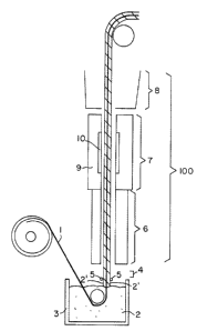
Brief Description of the Drawing
Fig. 1 shows a schematic of an apparatus for car-
rying out the method of the invention.
Detailed Description of the Invention
In accordance with the invention, halopolymeric
films are formed by casting onto a carrier belt having low
thermal mass. This carrier belt is preferably part of a
casting apparatus such as that depicted in Fig. 1. The
carrier belt 1 is dipped through a halopolymeric dispersion
2 in a dip pan 3 at the base of a casting tower 100 such
that a coating of dispersion 2' forms on the carrier belt 1.
The coated carrier belt 1 then passes through a metering
zone 4 in which metering bars 5 remove excess dispersion
from the coated carrier belt. After the metering zone, the
coated carrier belt passes into a drying zone 6 which is
maintained at a temperature sufficient to remove the carrier
liquid from the dispersion giving rise to a dried film. The
carrier belt with the dried film then passes to a bake/fuse
zone 7 in which the temperature is sufficient to consolidate
or fuse the halopolymer in the dispersion. Finally, the
carrier belt passes through a cooling plenum 8 from which it
can be directed either to a subsequent dip pan to begin
formation of a further layer of the film or to a stripping
apparatus, such as that illustrated in U.S. Patent No.
2,852,811.
In a preferred embodiment of the invention, the
bake/fuse zone 7 is heated using dual heat sources, a con-
ventional oven 9 that maintains the temperature at about
300-F to 710-F, and a radiant electric heater 10 that raises
web the temperature to one sufficient to consolidate the
polymer, e.q., about 700-F or higher in the case of PTFE.
The method of the invention provides superior
performance by varying several aspects of the previously
known method for casting fluoropolymer films: (1) the
nature of the carrier or casting medium, (2) the nature of
the casting fluids, (3) the nature of the metering methods
used to apply the casting fluids to the carrier, and (4) the
state of consolidation of the polymers as they proceed from
the drying fluid to the fused and recrystallized or solidi-
fied films. Each of these requires some discussion to
understand the significant advances of the present invention
as distinguished from the prior art.
-12-
1. Nature of the Carrier
The state-of-the-art teaches the suitability of
metallic carriers which are preferably made of stainless
steel polished to a specific surface smoothness to maintain
sufficient adhesion to hold the in-process film to the car-
rier, but not so rough as to provide an anchorage which
could prevent stripping entirely or lead to distortion of
the film during stripping. Aluminum foils are also useful
as a carrier, but are less satisfactory than stainless steel
for several reasons: they are quickly annealed during high
temperature fusing of the applied polymers and, therefore,
readily damaged in subsequent use. They are also prone to
creasing or wrinkling in-process and susceptible to chemical
modification of their surfaces by the aqueous ammoniacal
solutions characteristic of many fluoropolymer dispersions.
The primary disadvantage of the preferred stain-
less steel carrier of the prior art is its need to be fully
tempered and relatively stiff for tracking purposes. This
results in a carrier with sufficient stored mechanical
energy under tension to be difficult to manage at high
speed. Thus, while suitable at line speeds of 3 to 8 fpm,
it is not a good candidate for higher speed (10 to 30 fpm)
operation. Additionally, the actual adhesion of consolidat-
ed fluoropolymer films to the steel is a function of the
-13-
~ 3 ~
number of uses of the steel belt which needs periodic re-
furbishment to reestablish appropriate adhesion for strippa-
bility. Lastly, at the 5 to 8 mil gauge employed for track-
ability/mechanical stability, the steel belt possesses sub-
stantial thermal mass relative to the much thinner (0.15 to
1.5 mil) depositions of resin in any one lamellae. This
leads to repeated heating and cooling requirements in the
casting process which is wasteful of energy and limits the
rate at which the polymers can be quenched. The slow cool-
ing that results can have an impact on the quality of the
product film, particularly in the degree of crystallinity.
The invention overcomes these difficulties by
using superior carriers that are thinner and that exhibit
lower adhesion to the polymeric films and thereby better
facilitate strippability. These materials also possess
lower thermal mass, facilitating rapid quenching to yield
exceptionally low crystallinity in the films. The carriers
used in the invention are also less stiff and may be tracked
using rollers in contact with the surface of the coated
carrier belt, a method allowing very high speed operation at
continuously variable widths. This latter feature can sig-
nificantly reduce material yield losses.
The actual choice of carrier for any given film is
dictated by the highest process temperature it will encoun-
1311 ~3
ter, the work of adhesion developed between the carrier andthe film surface in direct contact with it, and its chemical
compatibility with the casting fluids. In general, the
carrier should be of low thermal mass, dimensionally stable
at the maximum processing temperature, chemically resistant
to all components of the casting fluids, and the work of
adhesion between the deposited film and the carrier surface
must not exceed the yield strength of the deposited film.
Once these conditions are satisfied, the actual selection of
a carrier for any given film from all carrier candidates is
a matter of taking into account its useful life as well as
its initial cost for the sake of economy.
Suitable carriers for casting of the invention
films include:
(a) Films of high melting thermoplastics, such as
the thermoplastic polyimides (e.q., Upilex~ from ICI),
polyether-ether ketones (e.g., STABAR~ from ICI),
polyaryl ketones from Union Carbide, polyphenylene
sulfide (~ ~ , RYTON~ from Phillips Corp.), and
polyetherimides (e.q., ULTEM2 from General Electric
Co.). High melting perfluoropolymeric films may them-
selves be used for casting of the lower melting, par-
tially fluorinated copolymers, such as TFB 7100D (a
terpolymer of VF2, TFE and HFP) from Hoechst.
--15--
131~¢3~3
(b) Films of thermosetting plastics, particularly
of the high temperature capable thermosetting resins
such as polyimides (~ , Kapton0 H from DuPont) are
particularly good carriers since they possess excellent
high temperature thermal and dimensional stability as
well as durable release characteristics. The surface
free energy of the Kapton0 H is reported to be about 45
to 55 ergs/cm, yet has somewhat surprisingly proven to
be an excellent candidate for accepting the casting
fluids which typically have a surface tension of about
29 to 35 dynes/cm. It is suspected that certain addi-
tives in the casting fluids in some way abets wetta-
bility.
(c) Coated or laminated textiles based upon the
above thermoplastics or similar thermally stable resins
and thermally stable reinforcements such as fiberglass,
graphite, polyaramid (e.q., Kevlar0), and aromatic
polyamide (e.q., Nomex0) yarns may also be used as a
carrier to maximize dimensional stability at high tem-
perature as opposed to an unsupported film. To avoid
excessive stiffness in an otherwise suitable coated or
laminated textile, it is desirable to employ a more
flexible coating resin as a subsurface coating followed
by a top-coat or lamination of the otherwise desirable,
13~a,~3
but too stiff composite. For example a PTFE perfluoro-
plastic or "Kalrez" perfluoroelastomeric coating on a
thin, woven fiberglass substrate (e.q., Style 104 or
116) may be provided with an polyimide surface by top-
coating or laminating.
(d) Plastic Coated Metal Foil may be used as a
carrier. While a thin metal foil, such as a 3 mil
aluminum foil, has the disadvantages previously cited,
a relatively thin coating of one of the aforementioned
thermoplastics or thermosetting resins or a thin metal
foil could provide an acceptable casting medium es-
sentially without those deficiencies.
(e) Metallized or Metal Foil Laminated Plastic
Films may be used as carriers. Any of the acceptable
plastics, or even elastomers, in thin sheet or film
form could be metallized or laminated between very thin
metal foils to provide the good wettability and release
properties of the metal while eliminating their disad-
vantages. In particular, a high temperature cured
fluoroelastomer even in very thin (about 2 mil) sheet
form sandwiched between thin aluminum foils could have
excellent utility as a casting medium. Similarly the
coated or laminated textiles mentioned in (c) above
could be laminated between metal foils to provide a
* Trade Mark
-17-
131 ~3
metal surfaced, dimensionally stable high temperature
carrier with excellent toughness (tear resistance) to
improve durability in use, compliance to roll and
metering surfaces in the equipment, while offering
excellent strippability and fluid wettability.
It is clear from this discussion that a large
number of carrier options exist for the invention process
which go well beyond the metal carriers of the prior art.
This is true not only for lower temperature processes for
casting low melting polymers, but even for the highest melt-
ing perfluoropolymer (PTFE) for which a polyimide casting
surface is in fact preferred, and which exhibits excellent
performance as demonstrated in the Examples. Such a surface
is also suitable for casting TFE copolymers with perfluoro
(propyl vinyl ether) such as Teflon PFA. This latter
observation is rather surprising since the Kapton~ F pro-
ducts are based upon reasonably well-bonded Teflon~ FEP and
PFA coatings on Kapton~ H. This would seem to speak to a
requirement for close control of the thermal history of such
copolymers in contact with a carrier containing polyimide
resin on its surface as a film or coating.
2. Nature of the Casting Fluids
The casting fluids of the prior art contain
relatively high percentage of surfactant, e.q., about 12% of
-18-
the surfactant Triton~ X-100 (octyl phenoxy polyethoxy
ethanol), by weight based upon resin solids and it is taught
that this is required to improve the wetting characteristics
of the casting fluids on the metal carrier. It is also
taught that 6% Triton~ X-100 is insufficient for uniform
wetting, while more than about 12% leads to non-uniform film
thickness by increasing the viscosity of the fluid.
In contrast, the Examples in accordance with the
present invention indicate that less than about 12%, namely
less than about 6% surfactant, such as Triton~ X-100, is
effective in the dispersions employed to produce high
quality films at high linear web rates. Thus, it appears
that the incorporation of a metering device allows a
reduction in the amount of surfactant previously required in
the prior art processes. While not intending to be limited
to a particular mechanism, it is believed that this occurs
because the prior art process relied upon the solids level
(specific gravity of the casting fluids) to control the
thickness of the deposited resin on each pass. The
viscosity of such dispersions is very low, generally less
than about 17 cp at 60% solids, and this low viscosity is
required to limit the buildup of resin to less than about
0.37 mils per pass, the critical cracking thickness of such
--19--
~ 3 ~ 3
dispersions; i.e., the thickness above which mud-cracked
deposits form upon drying of the dispersion.
Using the invention, however, it was found that
excellent quality films may be produced at high carrier
speeds, and at lower surfactant levels ~ , about 6%
Triton~ X-100), and that solids levels up to about 60% may
be employed to obtain films of excellent quality. This is
advantageous as it reduces the amount of surfactant and
dispersion liquid that must be removed in the drying zone
and the bake/fuse zone. Further, the wetting
characteristics of the casting fluids may be controlled by
means of additional fluorosurfactants, for example
fluorinated alkyl polyoxy ethylene ethanol surfactants, such
as Fluorad~ FC-170C from 3M or silicone-based surfactants
such as Union Carbide's L-77. These surfactants are
effective in reducing the surface tension of the casting
fluids in much more modest quantities than is Triton~ X-100,
and they can be more rapidly eliminated by thermal
decomposition, volatilization, or sublimation in the baking
zone of the invention art equipment.
It was also surprisingly found that uncracked
resin deposits can be formed at thicknesses well in excess
of the critical cracking thickness associated with the dis-
persions employed. As mentioned in Example 5 hereinbelow,
-20-
~ 3 ~ 3
this is not fully understood, but may relate to the fact
that one of the ionic additives employed, FC-170C, is known
to promote a rapid increase in fluid viscosity at elevated
temperatures in the case of Triton~ X-100 containing dis-
persions. It is speculated that as the dispersion starts to
dry at the very rapidly increasing temperatures characteris-
tic of high speed processing, the drying resin has less time
to drain itself of water prior to evaporation, resulting in
a thicker resin deposit of lower apparent density prior to
complete drying. Consequently, the deposit is less prone to
crack if the shrinkage forces which induce cracking are
dependent upon more intimate particulate contact. The well
known tendency of dispersion-derived PTFE to fibrillate upon
intimate particulate contact may in fact be the phenomenon
responsible for the mud cracking ordinarily observed when
PTFE dispersions dry in the presence of more modest
time/temperature gradients than those characteristic of the
invention process. This could also account for the sur-
prisingly good mechanical qualities of the films made by the
invention process after final fusion.
It is desirable, in general, to identify the most
appropriate hydrocarbon surfactant(s) for any given casting
fluid which in combination with relatively minor quantities
of fluorosurfactants yields the desired result of high
-21-
~31~X~3
deposition rates (build per pass) without cracking, and
facile decomposition, volatilization, or sublimation of
non-polymeric additives. Since the maximum temperature
desirable for film consolidation upon final fusion will
depend upon the melting point of the specific polymers in
the films, the optimum level and chemical nature of such
surfactants can be different for various film compositions.
Ionic additives other than the fluorosurfactants may be
employed to advantage in casting fluids to engender a rapid
increase in viscosity upon drying. These could include
salts such as ammonium acetate, or other salts equally fugi-
tive in the process, or salts such a potassium chlorate
which can induce decolorization of the fused films at very
minor levels. Such casting fluids which contain specific
additives contributing to the high quality of the films
produced by the invention process are well beyond the simple
surfactants associated with the prior art process for film
casting.
3. Nature of the Methods Used to Apply the Cast-
ing Fluids to the Carrier
The prior art casting process is essentially a
free dippinq process in which the only significant control-
ling factors of the amount of resin deposited on the carrier
are the solids level in the dispersion and linear carrier
rate. Thus, for any given fluid, the web speed is limited
-22--
J ~.~ 3
to a maximum carrier speed above which the pick up of resin
on the carrier exceeds the critical cracking thickness.
This limitation, combined with the limitations imposed by
metal carrier belts and the deterioration of product quality
noted at high carrier speeds led to usage of carrier speeds
of 3 to 8 linear feet per minute in most cases.
In the method of the invention, however, metering
bars are used to enable much more rapid linear travel of the
carrier, up to at least 6 times that of the prior art
process. In the process of the invention, the speed of the
carrier belt is limited essentially only by the length of
the drying/fusing zone, i.e., the carrier cannot move so
rapidly that drying does not occur within the drying zone
provided and fusion within the fusing zonè provided. The
wiping action of the metering bars removes the excess
casting fluid associated with high speed carrier travel so
that an uncracked deposit of dried resin may be obtained
prior to final fusion of that deposit.
The selection of metering bars, however, is not
trivial since it is undesirable to introduce shearing of the
casting fluids sufficient to coagulate the resin contained
in the reservoir between the cavities of the metering bar
and the moving carrier. The size and shape of the metering
cavity is dependent upon the shear stability of each speci-
fic casting fluid. Additives to minimize polymer shearingby the metering bars may also be used in the casting formu-
lations. For example, foaming at the metering bars over an
extended period of time could be introduce unacceptable
shearing at the bars. This may be ameliorated by using an
antifoam such as Dow-Corning FG-10, as well as fluorosurfac-
tants such as 3M's Fluorad~ FC-146 (perfluoroammonium
octanoate). Since the invention fluids can contain widely
different polymers with particles of varying shear sensitiv-
ity, variable solids content, particle size, and surfactant
systems, the selection of a bar geometry (cavity size and
shape) specific to any given casting fluid is more difficult
to model than to identify by trial and error. The Examples
provided herein indicate the general variety of bars (and
therefore cavities) which have facilitated the production of
high quality films by the invention process at high produc-
tivity.
4. Nature of the State of Consolidation of
the Casting Fluids and Resins From
Metering Through Drying and Fusion
The prior art process may be characterized as
providing an effective and very simple means to deposit
casting fluids on a carrier at a rate which is limited by
the critical cracking thickness of the casting formulation.
The drying of the casting fluids of the prior art process
- -24-
~L3~û3
occurs at a relatively modest thermal gradient and over a
relatively long time and is a function of the web speed and
drying/b~king temperatures. Fusion and recrystallization
occurred over periods of about 2.5 minutes up to as much as
35 minutes or more, leading to good quality films, but low
productivity.
In the method of the invention, consolidation from
resin containing fluid to the final fused film proceeds over
a much shorter time. Specifically, the total residence time
in each of the drying zone and the bake-fuze zone is prefer-
ably less than about 1.5 minutes, most preferably less than
1 minute and may be substantially shorter. This can lead to
a higher than critical cracking thickness build rate of
uncracked resin deposits which can increase real productivi-
ty by at least 30% in the case of monolithic PTFE films.
Combining that productivity with even a 4 times improvement
in linear travel rate for the carrier can lead to a 520~ im-
provement in space/time yields, i.e., the number of pounds
of film produced per hour relative to the prior art process
in the case of PTFE. Other resin formulations will have
quantitatively different improvements in productivity, but
wou}d be expected to be qualitatively similar. This level
of improvement in the productivity of the invention process
results, in fact, in the space/time yields approaching or
-25-
3 ~,
exceeding that of a melt extruder for fluorpolymers such as
FEP. Thus, the invention process has the desired character-
istics of high productivity and high quality at a cost com-
parable to that of extruded films.
It is characteristic of the invention method that
a shorter total residence time is employed for evaporation
of the water, baking of the dried solids, and fusion of the
baked solids to a polymeric melt that has heretofore been
described for fluoropolymer film production. The actual
time during which the polymers are actually in the melt,
undergoing consolidation at the highest process temperature,
is shorter than that of the prior art, but nonetheless
results in excellent consolidation as judged by the ultimate
tensile strength and elongation of the film produced.
Additionally, the rate of recrystallization/solid-
ification of the melt is much more rapid than in the prior
art process. This results in a film of greater optical
clarity, particularly in the case of PTFE containing film.
Since the rate of recrystallization of PTFE is a strong
function of cooling rate, it is believed that such films
produced by the invention process are either lower in cry-
stallinity level, or the domains of crystallinity are
smaller than can be achieved by prior art methods of cast
film manufacture. This is corroborated by a somewhat lower
-26-
melting point and heat of recrystallization for PTFE films
produced by the invention process.
Thus, films produced by the invention process are
expected to have greater flexural endurance and lower flex-
ural modulus than films produced by the prior art process,
particularly in the case of PTFE containing films.
The method of the invention can also be used to
produce complex multi-layer films with a very wide range of
compositions, some of which could not be produced by melt
extrusion at all due either to a disparate range of melting
or decomposition temperatures, so to disparate ranges of
melt viscosities for the resin blends. In particular, the
method is useful for producing fluoropolymeric films in
which the fluorpolymer i9 selected from the group consisting
of fluorine-containing homopolymers, copolymers and terpoly-
mers of tetrahaloethylenes, vinyl fluoride, vinylidene fluo-
ride, hexfluoroproplylene, perfluoroalkyl vinyl ethers,
ethylene and propylene. Moreover, degradation of properties
due to thermal exposure is dramatically reduced as a result
of the exceedingly brief exposure to consolidating (fusion)
temperatures. Thus, the invention provides improved produc-
tivity and, in many cases, superior products than the prior
art casting processes.
-27-
~ 3 ~ 3
In accordance with this invention, the term
"halopolymer" includes homopolymers, copolymers and
terpolymers of halogenated vinyl monomers, halogenated
alkylvinyl monomers, halogenated alkylvinyl ether monomers,
halogenated oxa-alkyl vinyl ether monomers, ethylene, and
propylene. -
The invention will be further illustrated by wayof the following non-limiting examples.
Example 1
The casting tower utilized was composed of a dip
pan under a 16 foot vertical oven divided via air flow into
an 8 foot drying zone and a bake/fuse zone of 8 feet. Cap-
tured within the 8 foot bake/fuse zone was an electric radi-
ant zone of 4 feet vertical height, with a maximum watt
density of 22 watts per square inch. After passing through
the tower the web was cooled by a cooling plenum, and then
passed over a head roll on its way to the windup. A high
quality PTFE film was cast on a .005 inch thick polyimide
film carried (Kapton~ H from E.I. DuPont) in five successive
passes to obtain a .002 inch thick PTFE film with an ulti-
mate tensile strength of 6902 psi and an ultimate elongation
of 695~. To do this, an Algoflon~ dispersion (D60 Exp 1
from Ausimont) was let down to a specific gravity of 1.34
with water. To this was added Union Carbide L-77 surfactant
-28-
13~3'3~3
at 1.0% by weight of the liquid. This dispersion was
metered onto the carrier by using 1 inch diameter stainless
steel metering bars, wound with .040 inch stainless steel
wire on each face of the carrier. The metering bars were
located about 12 inches above the dispersion bath with 2
inches vertical separation and approximately 1/2 inch over-
lap. The carrier was run at 17 fpm. The tower heat condi-
tions were determined by the following set points: drying
zone/250-F, bake-fuse zone/300~F, radiant electric zone
controlled to give a web temperature of 770~F as measured by
an optical pyrometer. Multiple test samples (1/2" x 8")
gave an average ultimate tensile strength of 6240 psi and an
average ultimate elongation of 595%. The quality of this
film, produced at a linear rate about 3.4x that of prior art
casting methodology, is significantly better than the prior
art films produced by cas~in~ at lower carrier rates with
longer drying and baking times (4000 to 4500 psi and 400 to
450% ultimate tensile strength and elongation, respec-
tively).
Example 2
A muilti-pass high quality film was produced on
the pilot tower (previously described in Example 1) utiliz-
ing the following procedure. Algoflon~ D60 Expl resin was
let down to 1.49 specific gravity with a 6% Triton~ X-100
-29-
~ 3 ~ 3
solution in water. To this was added 200 cc per gallon of a
5% stock solution of 3M fluorosurfactant FC-170C in water.
Also added at 2~ by weight of solids was a gold pigment
(Mearl Corp Super Gold 239Z). This dispersion was metered
directly onto a .005 inch thick polyimide (Kapton~ H) car-
rier using 1/2 inch diameter #22 wirewound metering bars for
four passes (bars located as previously described) and a
coarser metering bar (l/2 inch diameter bar wound with #30
wire overlayed with #5 wire) for the fifth pass. The dis-
persion bath was then changed to DuPont T30B PTFE resin
dispersion which had been let down to 1.40 specific gravity
with a 6% Triton~ X-100 (Rohm and Haas) solution and lO0 cc
per gal. of the previously described 5% fluorosurfactant
stock solution. To the dispersion was added 8% by weight of
solids of Borden's Aquablack AB 135 pigment. Two passes of
this black formulation were then metered onto the "Gold"
PTFE cast film using the "5 over 30" metering bars. A final
pass of DuPont's TE9503 FEP dispersion at a 1.25 specific
gravity (let down with water) was then metered on as a
bonding layer. All passes were run at a web speed of 22
fpm. The previously described casting tower had a drying
zone temperature set point of 250-F with a bake and fuse
zone temperature set point of 680~F. The radiant zone was
set to control at 760-F for the gold passes and at 720~F for
* Trade Mark
-30-
the black passes and the FEP pass. The final film was .0039
inches thick, readily removed from the carrier, and of
excellent physical properties for a filled resin. Physical
testing indicated an ultimate tensile strength of 5244 psi
and a 470~ ultimate elongation, at least as good a quality
as that which would be obtained by prior art casting metho-
dology but obtained at a 4.5x web rate.
Example 3
To show the effect of reduced thermal mass, a .002
inch thick PTFE film was cast on a .003 inch thick aluminum
foil carrier in six passes using the previously described
casting tower. The PTFE dispersion was DuPont's T3 OB let
down to a 1. 34 specific gravity with water. The dispersion
was metered on to the aluminum foil using 1 inch diameter,
#40 wirewound metering bars, as described in previous Exam-
ples, at 14 fpm carrier speed. The tower was set for a
drying zone temperature of 250~F and a bake-fuse zone tem-
perature of 680-F for the first two passes. The upper zone
was increased to 710~F for the next four passes. The final
film was stripped from each side of the carrier with minimal
difficulty, and had a tensile strength of approximately 4500
psi, as good as that obtainable with prior art casting meth-
odology but produced at a 2.8x linear web speed. Although
this unmodified aluminum foil carrier is probably unsuitable
-31-
~ 3~ ~~
for routine use as it annealed during the bake/fuse step, it
shows that reduced thermal mass carrier with aluminum sur-
faces would be suitable if used in forms less sensitive to
thermal effects as described hereinabove.
Example 4
A very high quality thin PTFE film was cast in
four passes at 25 fpm web speed for each pass. The pre-
viously described casting tower was set for a drying zone
temperative of 250~F, a bake-fuse temperature of 680~F, and
a radiant zone control temperature of 770-F. The PTFE dis-
persion employed was Algoflon~ D60 Exp 1 which had been let
down to l.S0 specific gravity with a 6% Triton~ X-100 and
water solution. To this was added the previously described
5% stock solution of FC-170C (100 cc per gallon of disper-
sion). The dispersion was metered onto the .005 inch thick
polyimide film carrier (Kapton~ H) using 1/2 inch diameter,
#14 wirewound bars. The resulting .0011 inch thick film had
an ultimate tensile strength as high as 70Z9 psi and an
ultimate elongation of 550%. This dramatic improvement in
quality relative to similar films produced by the prior art
casting methodology was obtained along with a 5x improve-
ment in productivity as measured by relative linear web
rates.
- -32-
3 ~
Example 5
In this example a high quality film was achieved
using high speed film production techniques on a .005 inch
polyimide carrier (Kapton~ H) using the previously described
casting tower. The PTFE dispersion was Algoflon~ D50 Exp 1
(Ausimont) let down to 1.50 specific gravity with a 6% Tri-
ton~ X-100 solution and 100 cc per gal. of FC-170C 5% solu-
tion as previously described. The dispersion was metered
onto the carrier in six passes using 1/2 inch diameter, #26
wirewound bars at 25 fpm linear web speed. The final film
stripped easily from the carrier and was .0038 to .0040
inches thick. Its ultimate tensile strength was as high as
6350 psi and its ultimate elongation was 640%: a forty per-
cent improvement in tensile strength and elongation with a
5x improvement in productivity relative to prior art casting
methodology. The thermal settings for this run were: drying
zone/250-F, bake-fuse zone/680-F, radiant zone/auto con-
trolled at 770~F. The build of resin per pass was in excess
of .00067 inches, significantly greater than the 0.0004 to
.00045 inches one would predict from measurements of criti-
cal cracking thickness associated with this dispersion.
While not fully understood, this behavior is reproducible
and is believed to be associated with the dynamics of the
fluid consolidation to a dried but uncracked film (while
still unfused) in the thermal environment of this particular
tower. This condition appears to lead to uncracked films,
surprisingly about 50% thicker than expected and of very
high quality.
Example 6
In this example a high qualify film was achieved
using high speed film production techniques on a .005 inch
polyimide carrier (Kapton~ H) using the previously described
casting tower. The PTFE dispersion was DuPont T30B let down
to 1.33 specific gravity with water. The dispersion was
metered onto the carrier using 1 inch diameter, #40 wire-
wound metering bars, yielding a 3.3 mil film in seven
passes. The thermal settings for this run were: drying
zone/250~F, bake-fuse zone/710~F, radiant zone/auto con-
trolled at 780~F. The carrier rate was 26 feet per minute.
The following Table indicates some significant
differences between this film, cast PTFE films of the prior
art, and skived PTFE film.
- -34-
~ 3 ~
C~ , ,
` , ~ ~
, ~ ~ ,,
~1 ~
~ o o o
~ +t +l +l
o ~ o
~ U~
~ r~ ~
E~ ^ I
r~
.' o ~o
U~ ~, X oo ~ ~ .~
~ ,~
.r~ ~ O O O O
o~ o2
C ^
, o~
,~ C
J- o o O E~
. ~ U~
r! a c
,. ~ ~ U~ o o
~ 00 C~ o ~,
C In U~
_
V~
.. ~ C
C o o o
~ a u~ u~ ,, O
E~ ~ I~ ~ u~ ~
U~
I~
,
.,,
ô
o ¢ ~
.- V ~ C 0
o
~o ¢* ~-~
,, g ~ C
E~ O ~
o J~ ~ h
tO ~
--35--
~ 3 ~
These data demonstrate the more anisotropic
elongation of the cast films vs skived films, with the
invention film being clearly the most isotropic. The
reduced elastic modulus of the cast films is also evident.
The melting point (Tm) of the cast film made by
the invention method is significantly lower than the prior
art cast film and its heat of fusion (~m) is drastically
reduced. The observation of pure PTFE with a melting tem-
perature below 325-C and a heat of fusion less than 22
joules/gram is indicative of a film with greater optical
clarity suggesting lower crystallinity or smaller crys-
tallinites. Further, this behavior should extend to mix-
tures of PTFE with other materials, although the exact num-
bers will depend on the proportions and the amount of effect
on freezing point due to interactions of the polymers.
-36-