Note: Descriptions are shown in the official language in which they were submitted.
~2~
MAMAGEMENT SYSTEM CAPABLE OF QUICKLY
ASSIGNING A TERMINAL ENDPOTNT IDENTIFIER
TO A TERMINAL EQUIPMENT UNIT
~ackground of the Invention:
This invention .relates to a management system
for use in an inteqrated services digital network (will
be often abbreviated to ISDN) to manage a plurality of
5 terminal endpoint ident.ifiers (TEI) which are assigned
to a plurality of terminal equipment (TE) units.
An integrated servlces digital network of the
type described comprises a digital exchange conn:ected to
a plurality of networ~ termination (NT) units through
10 digital subscrlber lines. To each of the network
termination units, a subscriber b~s or ano-ther network
termination uni-t is extended to at least one socket
element. Each socket can be used in common to di:E~erent
kinds of terminal equipment (TE) units, such as a
15 telephone set, a personal computer, a facsimile device,
or the li.ke. With this struc-ture, each user is
communicable with another device through the integrated
. - ~ . .
. .
~ 3 ~ 2
services digital network by selectively connecting each
of the terminal equipment units -to the soc]cet. Such
communication is carried out by the use of a pair of
information transfer channels or communication channels
5 (called B-channels) and a contro] channel (called
D-channel) which are multiplexed in a time division
fashion. Thus, it is possible to favorably offer a wide
variety of services to the users.
In order to enable the above-mentioned
10 communication of various kinds of terminal equipment
units, a protocol is prescribed in connection with an
in-terface between users and such an integrated services
digital network by recommendations of International
Telegraph and Telephone Consultative Communication
15 (CCITT). More specifically, a protocol for such an
interface is hierarchically divided into first, second,
and third layer protocols which define a procedure
be~ween terminal equipment units and network termination
(NT) units, a procedure for a D-channel link access, and
20 a procedure for call control from a beginning of
communication to an end thereof, respectively.
The following description will be mainly
dixected to the protocol for the second layer protocol,
which is determined for accessing a link on the
25 D-channel and which may be called a link access
procedure on the D-channel (LAPD). Inasmuch as various
kinds of the terminal equipment units can be selectively
connec-ted to a single socket in the integrated services
'
~32~
digital network, it is necessary to identify whether or
not such a terminal equipment unit is connected to the
socket each time when communication is carried out
through the socket.
According to the link access procedure on the
D-channel (LAPD), when a selected one of the terminal
equipment units is connected to the socket and is
powered on to access the integrated services digital
network and to set up a data link between the selected
10 terminal equipment unit and the integrated services
digital network, a request is at first issued from the
selected terminal equipment unit to the integrated
services digital network. Responsive to the request,
the integrated services digital network searches for an
15 unused or idle one of terminal endpoint identiiers
(TEI) managed by the integrated services digital network
and assigns the ~mused terminal endpoint identifier as
an assigned terminal endpolnt identifier to the selected
terminal e~uipment unit with the assigned terminal `-
20 endpoint identifier retained or registe.red in the
integrated services digital network.
Thus, an unused terminal endpoint identifier is
pre~erentially assigned to each terminal equipment unit
each time when the integrated services digital network
25 is accessed~ As a result, assigned terminal endpoint
ident.ifiers are success:ively registered on a
registration table of the integrated services digital
network.
~2~2
Herein, it is to be noted that such assigned
terminal endpoint identifiers are not eliminated from
the registra-tion table even when the terminal equipment
unit is disconnected from the in-tegrated services
5 digital network ater completion of communication.
Under the circumstances, let a following one of the
terminal equipment units issue a following or new
re~uest of assignin~ or granting a terminal endpoint
~ identifier on condition that no unused terminal endpoint
10 identifier remains in the integrated services digital
network. In this event~ the integrated services digital
networ]s manages and checks whether or not all of the
terminal equipment units have been actually connected to
the integrated services digital network ye~.
15 Specifically, if a certain one of the terminal equipment
units is disconnected from the integrated services
digital network, the integrated services digital network
assigns, to the following terminal equipment unit, a
terminal endpoint identifier which is previously
20 assigned to ~he certain terminal equipment unit. On the
other hand, when the certain terminal equipment unit has
been connected to the integrated services digital
networlc~ similar checking operation is carried out as
regards a different one of the terminal endpoint
25 identifiers and is successively continued until an idle
terminal endpoint identifier is found out by the
integrated services digital network. At any rate,
checking operation must be pro5ecuted in accordance with
~ 3 2~ J
a terminal endpoint identifier assignment procedure
prescribed in the CCITT I.441.
From this fact, i-t is readily understood that
the integrated services digital network has a variable
5 response time to a request of assigning or granting a
terminal equipment identifier. This shows that a long
time is wasted top set up a data link in spite of the
fact that -the data link must be quickly set up at a high
speedO
5ummary of the Invention:
It is an object of this invention to provide a
management system which is capable of quickly setting up
a data link in an integrated services digital network.
It is another object of this invention to
lS provide a management system o the type described~
wherein an idle terminal endpoint identifier is quickly
assigned to each terminal equipment unit.
It is still another object of this invention to
provide ~ management system of the type described,
20 wherein checking operation is useless in accordance with
a terminal endpoint identifier assignment procedure
prescribed in the CCITT I.441.
A management system to which this invention is
applicable is for use in managing a plurality of
25 terminal endpoint identifiers which are to be
selectively and variab]y assigned to terminal equipment
units connected to an integrated services digital
network. According to this invention, the management
., :
~ 3 2 ~
system comprises up-down counter means operable in
response to a count mode signal representative of a
selected one of a count--up and a count-down mode and to
a sequence of count pulses for counting the count pulses
5 to produce a count signal representative o~ a count
value to which the count pulses are counted by said
up-down counter means, memory means for memorizing a
threshold value signal representative of a predetermined
thresholfl value, comparing means responsive to the count
10 slgnal and the threshold value signal for comparing the
count value with the predetermined threshold value to
detect whether or not the count value is not smaller
than the predetermined threshold value and to thereby
produce a comparison signal when the count value is not
15 smaller than the threshold value, and operation control
means operatively coupled to the comparing means, the
up-down counter means, and the terminal equipment units
for controlling the up~down counter means and the
terminal equipment units. Such control operation is
20 carried out by sending, in response to the comparison
signal, a check request to assigned terminal equipment
units to which the terminal endpoint iclentifiers are
indivi.dually assigned~ by receiving individual responses
to the check request, by releasing non-reception
25 terminal equipment units from which no response is
received in the assigned terminal equipment units, and
by proclucing a count down signal representative of the
count-down mode and internal clock pulses equal in
~ 3 2 ~
number to the non-reception -terminal equipment units.
The management system further comprises means for
delivering the count down signal and the internal clock
pulses to the up-down counter means as the count mode
5 si~nal representative of the count-down mode and the
count pulses, respectivelyO
Brief Description of the Drawing:
Fig. 1 is a block diagram of a management system
according to a preferred embodiment of this invention;
Fig. 2 is a flow chaxt for use in describing
operation of the management system illustrated in
Fig. l; and
Fig. 3 is a block diagram of a part of the
management system illustrated in Fig. 1.
Description of the Preferred Embodiment:
Referring to Fig. 1, an integrated services
digital network is specified by an exchange which is
operable to manage terminal endpoint identifiers in
accordance with this invention and which may be
20 therefore called a management system according to a
pref~rred embodiment of this invention. The illustrated
exchange accommodates a plurality of subscriber lines,
each represented by a two-wire line 10 connected to a
pair of subscriber terminals ]1. The subscriber
25 terminals 11 may be connected either to a network
termination (NT) unit (no-t shown) or to a terminal
equipment (TE) unit (not shown). Each terminal
equipment unit is assigned with a terminal endpoint
~ 3 2 ~
identifier (TEI) when it is connected to each subscriber
line.
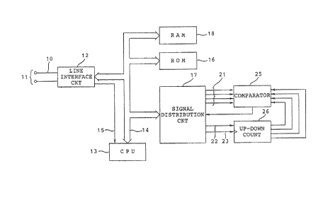
The illustrated exchange comprises a line
interface circuit 12 connected to the subscriber lines,
5 such as 10, and a central processing unit (CPU) 13
connected to the line interface circuit 12 through a
data~address bus 14 and an interruption line 15. The
line interface circuit 12 comprises a hybrid transformer
(not shown in this figure) for transform between the
10 two-wire line 10 and a four-wire line (not shown in this
figure), as will later be described. At any rate, it
suffices to say that the illustrated line interface
circuit 12 acts as a hardware interace for
serial/parallel data conversion, driving each subscriber
15 line, or the like in a manner to be described later.
To the data/address bus 14 are connected a
read-only memory (ROM) 16, a signal distribution circuit
17, and a random access memory 18. The signal
distribution ~ircuit 17 has an input port connected to
20 the data/address bus 14, a first output port 21, a
second output port 22, and a third output port 23. The
first OU tpUt port 21 is composed of a plurality of
output terminals connected to a comparator 25. The
second and the third output poxts 22 and 23 are
25 connected to an up-down counter 26 which is selectively
operable in a count-up mode and a count~down mode. To
this end, the up-down counter 26 has a mode terminal
~depicted at D/U) connected ~o the second output port 22
~2~
oE the signal distribution ci.rcuit 17 and a count
terminal (depicted at a triangle) connected to the third
output port 23 of the signal distribution circuit 17.
From this fact, it is readily understood that the signal
5 distribution circuit 17 supplies the up~down counter 26
with a mode signal representative o-f either the count-up
mode or the count-down mode through the second output
port 22 and with a sequence of count pulses through the
third output port 23. The up down counter 26 supplies
10 the comparator 25 with a count signal representative of
a count value by counting the clock pulses. In the
example being illustrated, the up-down counter 17 is put
into -the count-up mode and the count-down mode in
response to the mode signal of a logic "1" level and a
15 logic 1l0ll level, respectively. The count pulses are
given one at a time from the central processing unit 13
each time when the terminal equipment unit is connected
to the subscriber line. As a result, the count signal
of the up-down counter 26 is representative of the
20 number of the terminal equipment units which have been
actually conne~ted to the exchange.
The read-only memory 16 memorizes a control
program for controllin~ operations of the central
processing unit 13. In the illustrated example, the
25 read-only memory 16 further memorizes a maximum value
signal and a plurality of threshold value signals
representative of a plurality of threshold values,
respectively, which are different from one another, and
J~32~
which include a minimum threshold value and a maximum
threshold one. The maximum value signal indicates a
maximum value of the terminal endpoint identifiers -that
can be managed or monitored by the central processing
5 unit 13 and that may be equal to 12~. On the other
hand, the maximum threshold value is smaller than the
maximum value.
For brevity of description~ it will be assumed
that the illustrated read-only memory 16 memorizes only
10 first and second threshold value slgnals representative
of the minimum and the maximum threshold values,
respectively.
Referring to Fig. 2 afresh and Fig. 1 again, let
a terminal equipment unit be connected to the subscriber
15 terminals 11 ~Fig. 1~ and issue an identifier assignment
request code (often abbreviated to an ID code) to the
line interface circuit 12. In this connection, the
terminal equipment unit in question may be referred to
as a request terminal equipment unit. Specifically, the
20 identifier assignment request code carries an action
indicator and a reference number. As known in the art,
the action indicator specifies a predetermined number of
12~ in the identifier assignment request code while the
reference number is specified by a random number
25 generated within the request terminal equipment unit.
The identifier assignment request code, namely,
ID code, is sent from the request terminal equipment
unit to the illustrated management system. The
~32~2
11
managemen-t system carries out an operation of assigning
a selected one oE -the terminal endpoint identifiers to
the request termlnal equipment unit in a manner to be
described. In the illustrated example, the identifier
5 assignment request code is delivered to the central
processing unit 13 through khe line interface circuit
12. An interruption request is sent to the central
processing unit 13 through the interruption line 15 when
the ID code is received by the line interface circuit
10 12.
In the management system, the random access
memory 18 has a plurality of addresses which correspond
to the terminal endpoint identifiers and which store
status signals representative of whether the terminal
i5 endpoint identifier~ are being used or idle. The status
signals are assumed to be registered or held in the
respective addresses ~of the random acce~s memory 18.
The number o~ the status signals alls within a range
between 64 and 126, both inclusive.
On delivering the terminal endpoint identifiers
to the terminal equipment units, each terminal endpoint
identifier is practically preceded by a service access
point iflentifier (SAPI) stored in the random access
memory 18 also. A combination of the terminal endpoint
25 identifier and the service access point identifier forms
a data link connection identifier (DLCI), although
description will be omit-ted about the service access
~ 3 ~
12
point identiEier and the data link connection
identifier.
In Fig. 2, the central processing un.it 13 starts
the opera-tion at a first step Sl and proceeds to a
5 second step S2 of monitoring whether or not an ID code
is received by the central processing unit 13 through
the lnterxuption line 15. The second step S2 is
repeated until reception of any ID code and is followed
by a third step S3 of accessing the random access memory
10 18 to search for an idle one of the terminal equlpment
identifiers (TEI) when the ID code is received by the
central processing unit 13. Inasmuch as the random
access memory 18 is loaded with the status signals of
the terminal endpoint identifiers, as mentioned before,
15 the central processing unit 13 can detect each status of
the terminal equipment identifiers from the status
signals In this connection, it is unnecessary to carry
out a check routine which is prescribed by CCITT I.441
to assign the termi.nal endpoint identifiers to the
20 terminal equipment units, as will later become clear.
Accordingly, the central processing unit 13 can quickly
judge whether or not an idle terminal endpoint
identifier ~TEI) is presentO As a result, the central
processing ULIit 13 quickly assigns the idle terminal
25 endpoin-t identifier to the request terminal equipment
unit without making use of the check routine, as shown
at a :Eourth step S4, if the idle terminal endpoint
identifier is present. Otherwise, the central
~32Q~2
13
processing unit 13 rejects assignment of any terminal
endpoint identiEier to the request terminal equipmerlt
unit, as illustrated at the fourth step S4. When the
idl.e terminal endpoint identifier is assigned -to the
5 reques-t terminal equipment unit, the idle terminal
endpoint identifier is sent from the central processing
unit 13 as an identifier assignment code to the request
terminal equipment unit through the line interface
circuit 12.
In Fig. 2, the fourth step S4 is followed by a
fifth step S5 at which the signal distribution circuit
17 is energized by the central processing unit 13. This
shows that the signal distribution circuit 17 is
energized each time when the identifier assignment code
15 is produced from the central processing unit 13. More
specifically, the central processing unit 13 supplies
the signal distribution circuit 17 with the mode signal
of the logic "1" level representative of the count~down
mode and with a single one of the count pulses at the
20 fith step SS. The mode signal is delivered throu~h the
second output port 22 of the signal distribution circuit
17 to the mode termlnal D/U of the up~down counter 26
while the single count pulse is delivered through the
third output port 23 of the signal distribution circuit
25 17 to the up-counter 26. Conse~uently, the up-down
counter 17 is counted up by one to produce a count
5ignal C representative of a count value to which the
count pulses are counted by the up-down counter 26.
~1 3 2 ~
14
At a si.xth step S6, the central processing unit
13 aGcesSeS the read-only memory 16 to read the first
threshold value signal (depicted at THl in Fig. 2) out
of the read-only memory 16. The first threshold value
S signal THl is sent through the firs-t output port 21 to
the comparator 25. The count signal C is compared with
the first threshold value signa~ THl by the comparator
25 at a seventh step S7.
It is to be noted that an idle terminal endpoint
10 identifier remains when the count signal C represents
the count value smaller than the first threshold value.
Under the circumstances, if the count value is smaller
than the first threshold value, the comparator 25
produces an incoincidence signal of the logic "0" level
15 at an eighth step S8. The incoincidence signal is
supplied through the signal distribution circuit 17 to
the central processing unit 13. Responsive to the
incoincidence signal, the central processing unit 13
executes the second step S2 to monitor reception of a
20 following one of the ID codes.
On the other hand~ no idle terminal endpoint
identifier is left when the count value is equal to or
greater than the first threshold value, 50 far as the
status signals are concerned. Therefore, i~ the
25 comparator 25 judges that the count value is not smaller
than the first threshold value and produces a
coincidence signal of a the logic '!1" level, a ninth
step S9 follows the eighth step S8 to supply an
-
~
' '' .
~32~
identifier check request code to every one of theterminal equipment units that correspond to the terminal
endpoint identifiers currently registered in the random
access memory 18 and that may be referred to as
5 registered terminal equipment units. The coincidence
signal may be called a comparison signal.
It is to be noted that the registered terminal
equipment units may not always actually be connected to
the subscriber lines but may be disconnected from the
10 subscriber lines.
A-t a tenth step S10, the central processing unlt
13 monitors whether or not each of the registered
terminal equipment units is disconnected from the
subscriber lines. To this end, the illustrated central
15 processing unit 13 checks whether or not a response code
to the identifier check request code is transmitted from
every one of the registered terminal equipment units and
received by the central processing unit 13. Such a
response code may be called an identifier response code
20 and is supplied from each of the registered ~erminal
equipment units only when the registered terminal
equipment units are being connected to the subscriber
lines or the management system.
From this fact, it is readily understood that
25 the registered terminal equipment units may be regarded
as being disconnected from the management system or as
an inactive terminal equipment unit when no identifier
response code is transmitted therefrom.
~2~
16
If such an inactive termlnal equipmen-t unit is
present, the central processing unit 13 executes an
eleventh step Sll after the tenth step S10. Otherwise,
the tenth step Sl0 is followed by a twelEth step Sl2~
5 At the eleventh step Sll, the cen-tral processing unit 13
rewrites the status signal of the random access memory
18 at an address assigned to the inactive terminal
equipment unit and supplies the up-down counter 26 with
the mode sign~l representative of the count-down mode
10 and with a single one of the count pulses through the
signal distribution circuit 17~ Consequently, the
up-down counter 25 is counted down by one. Thereafter,
processing is returned back to the eighth step 58.
When all of the registerecl terminal equipment
15 units are connected to the management system, the
central processing unit 13 accesses the read-only memory
16 at the twelfth step Sl2 to reacl the second threshold
value signal ~depicted at TH2) therefrom. The second
threshold value signal TH2 is sent through the signal
20 distribution circuit 17 to the comparator 25 and is
compared at a thirteenth step S13 with the count value
represented by the count signal supplied from the
up-down counter 26. The second threshold value signal
TH2 is representative of the second threshold value
25 ~reater than the first threshold value, as mentioned
before. ~hen the comparator 25 judges -that the count
value C is smaller than the second -threshold value
(TH2), the thirteenth step S13 is returned ~ack to the
~ 3 2 ~ J
second step S2. Otherwise, the thirteenth step S13 is
followed by a fourteenth step S14 at which the cen-tral
processiny unit 13 recognizes absence of any idle
terminal endpoin-t identifiers. Subsequently, the
5 fourteenth step Sl4 is followed by the fourth step S4 to
reject assignment of a terminal endpoint identifier.
With this structure, the central processing unit
13 can quickly detect presence or absence of an idle
terminal endpoint identifier by searching for the random
10 access memory 18.
In addition, the threshold values are
successively changed from a small one to a laxge one.
Accordingly, the central processing unit 13 may not
monitor all the status signals of the terminal endpoint
15 identifiers. Therefore, it is possible to respond to
the ID code at a high speed,
Thus, a combination of the central processing
unit 13 and the line interface circuit 12 serves to
contro~ the up-down counter 26 and the signal
20 distributicn circuit 17 in cooperation with the terminal
equipment units and may be collectively called an
operation control circuit for controlling the up-down
counter 26 and the terminal equipme~t units. In
addition, the comparator 25 and the signal distribution
25 circuit 17 may be collectively called a comparator
circuit.
Referring to Fig. 3 to~ether with Fig. l, the
line int0rface Gircuit 12 is operable in cooperation
:L326~
18
with an exchange unit 31 which is included in the
exchange and which comprises a clock generator, a switch
section, and a switch con-troller. It is assumed that
the clock generator of the exchange unit 31 supplies a
5 sequence of clock pulses CK to the line interface
. circuit 12. A sequence of transmission data signals is
supplied from the switch section of the exchange unit 31
-to the line interface circuit 12 through a pair of
transmission communication channels Btl and Bt2. On the
10 other hand, a sequence of reception data signals is sent
from the line interface circuit 12 to the switch section
of the exchange unit 31 through a pair o~ reception
communication channels Brl and Br2.
The illustrated line interface circuit 12
15 comprises a transmisslon first-in first-out memory (TX
FIFO) 33 controlled by the central processing unit (CPU)
13 (Fig. 1) through the data/address bus 14 so as to
assign a transmission Gontrol channel Dt to the line
interface circuit 12. The transm.ission control channel
20 Dt serves to transmit a transmission control signal
which is successively supplied from the central
processing unit 13 to the TX FIFO 33. A multiplexer
(MUX) 35 is supplied with the transmission data signals
and the transmission control signal successively read
25 out of the TX FIFO 33 through the transmission
communicati.on channels Btl and Bt2 and the transmission
control channel Dt~ At any rate, a sequence of
mul-tiplexed digital signals is produced from the
, ~ ' .
'' ~ .
~2~
19
multiplexer 35 in accordance with ~ predetermined
format. The multiplexed dlgital signal sequence is
supplied through a digital to analog converter 36 to a
hybrid transformer 37 on one hand and to an echo
5 canceller 38 on the other hand. As a result, the
multiplexed digital signal sequence is sent from the
hybrid transformer 37 to the two-wire line 10 in the
form of a transmission voltage signal.
On the other hand, a reception voltage signal is
10 delivered from the two-wire line 10 to an analog to
digital converter 41 through the hybrid transformer 37
in the form of a sequence of reception digital signals.
The reception digital signal sequence is sent to the
echo canceller 38 to remove a near end noise and is
15 thereafter supplied to a demultiplexer (DEMUX) 42
operable in response to the clock pulse sequence CK.
Consequently, the demultiplexer 42 demultiplexes the
reception digital signal sequence into the reception
data signals and a reception control signal sent through
20 the reception communication channels 13rl and Br2 and a
reception control channel Dr, respectively. The
reception control signal may carry flags placed at a
start portion and an end portion. Supplied with the
reception control signal, a flag detector 44 detects the
~5 flags to send the interruption request to the central
processing unit 13 through the interruption line 15 when
the flag is detected at the end of the reception control
signal~ The remaining reception control signal between
~320~
the flags is delivered to a reception first-in first-ou-t
memory (RX FIFO) 45. Responsive -to the interruption
request, the central processing unit 13 accesses the RX
FIFO 45 to successively read the reception control
5 signal.
While this invention has thus far been described
in conjunction with a preferred embodiment thereof, it
will readily be possible for those skilled in the art to
put this invention into practice in various other
10 manners. For example, three or more different threshold
values may be memorized in the read-only memory 16 to be
changed from a minimum one to a maximum one.
Practicallyf operations of the signal dis-tribution
circuit 17, the comparator 25, and the up-down counter
15 26 may be implemented by the use of a microprocessor hy
software. In addition~ the random access memory 18 may
be loaded with the terminal endpoint identifiers
connected to the management system instead o the status
signals corresponding to the terminal endpoint
20 identifiers.