Note: Descriptions are shown in the official language in which they were submitted.
- 1 ~3~ 8
The present invention is relate~ to a pivot
mounting for a chair, especially an office chair.
Mountings of the above-mentiGned type are
known, making it possible to pivot the seat an~ the
back of the chair in relation to the chair support in
an acute angle backwards against the force of a spring
which is adapted to return the seat and the back to the
neutral position.
In a known embodiment a torsion spring in
the shape of a spring bar is arranged horizontally and
secured at one end to a pipe of which both ends are
mounted turnable in sleeves secured to the chair mount
for the seat. The other end of the spring bar pro-
trudes through the pipe and is secured to the seat
mount by a transverse arm on the spring bar. The end
of the transverse arm can be adjusted by means of a
spindle against the seat mount to achieve desired pre-
tensioning of the spring bar. Between the two sleeves
an arm is secured to the pipe and to a mount for the
chair support as well. In this manner the seat and the
back of the chair can be pressed by the user against
the force of the spring bar by twisting of the bar, and
the return force of the spring bar may be adjusted by
means of the transverse arm.
The above-mentioned design of a pivot mount
for a chair in many respects has proved suitability and
also is commonly in useO The mount, however, has a
relatively large structural length, and a reliable
mounting of the transverse arm to the spring bar is
re~uired.
The pivot mount according to the present
invention provides the advantages of the above-
mentioned mount with respect to the spring force
between the seat mount and the mount for the chair sup-
port, as well as adjustment of same. The mount
according to the invention, however, provides a
1~0118
- la -
substantially shorter structure length and makes th~
transverse arm redundant.
The above-mentioned advantages according to
the invention are achieved with the pivot mount for a
chair, especially an office chair, comprising a spring
bar arranged in a pipe in a direction transverse to th~
chair, where the spring bar with a tension connects the
two in relation to each other pivotable parts of the
moun-t, of which one is connected with the chair support
and the other part is connected with the pivotable part
of the chair, characteri~ed in that the one end of the
bar is secured to one end of the pipe, and the pipe
being secured to the second movable part, and the
second end portion of the bar being bent in a reverse
acute angle in relation to the remaining part of the
bar, the end of which with tension is abutting against
a stop connected with the second part, the stop prefer-
ably being adjustable.
The drawing discloses an embodiment o~ the
pivot
;i. L~/ . ,
52576 2 13~118
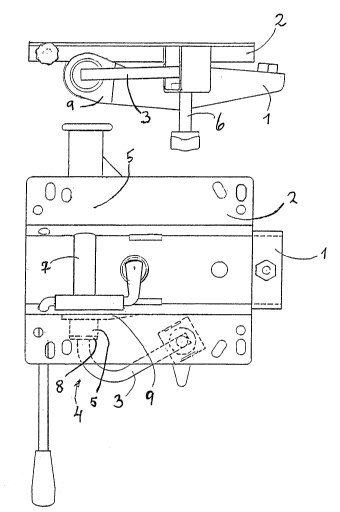
mount according to the invention, adapted to an office chair
where the seat is stationary and only the back can be pivoted.
The mount according to the invention may, ho"ever, be ad~p~ed
also to other desired purposes, such as chairs ~there the
5 seat as well as the back shall be pivotable.
In the drawlng, Fig. 1 discloses a side view of the
pivot mount according to the invention, Fig. 2 discloses
a top view of the mount in Fig. l, and Fig. 3 discloses a
view of the pivot mount as seen frorn left in Fig. l.
o The pivot mount according -to the invention comprises
principally two in relation to each other turnable or pivot-
able parts which are kept tensioned against each other b~
means of a spring device, the tension of which can be adjusted
by the user. When the pivot mount is adapted to chairs where
5 the seat and the back shall be pivotable together, these
are connected with one part, whereby the chair support is
connected with the other part.
In the drawing, however, an embodiment is disclosed
whei-e only th~ back is pivclable, whereas the-seat is statio-
2() nary and connected to the seat mount 2. Hereby also the seatmount in this embodiment is connected with the chair support,
whereas the pivotable back is connected with the back mount
1.
A sleeve 7 is welded to the seat mount 2. Through
25 the sleeve is arranged a pipe 5 through which a spring bar
4 is protruding. The spring bar 4 is kept centric at one
end of the pipe 5 by means of a plug 8 and is connected with
the pipe 5 at the other end.
The pipe 5 is turnable mounted in the sleeve 7. The
30 two side members 9 of the back mount l are secured to the
pipe 5 on each side of the s~eeve 7.
The spring bar 4 preferably has a square shape and
its end portion 3 is bent in an angle in relation to the
remaining portion of the spring bar. The end of the end port-
35 ion 3 is abutting against an adjustment screw 6 being connect-
ed with the seat mount 2. By mounting and welding the dirfer-
ent parts the end portion 3 of the spring bar is tensioned
against the adjustment screw 6 with a desired force.
52576 3
~3~118
As disclosed especially in Fig. 1, the back of th~
chair may be pivoted back-"ards whereby the back mount 1 i.,
pivoted clockwise on Fig. 1 against the force of the ~pring
bar 4, the straight portion of the spring bar 4, "ithin hD
5 pipe 5, thereby acting as a torsion spriny, whereas the end
portion 3 provides an additional resilient effect, due to
the material of the spring bar. When the force against the
back comes to an end, the back rnount 1 will be pressed ba-k
to the neutral position of the spring bar 4.