Note: Descriptions are shown in the official language in which they were submitted.
SPECIFICATION i 3 ~ ~ 2 4 6
Back~round of the Invention
The present invention relates to emergency
lighting systems, and more particularly to an emergency
lighting unit having a remote test feature and improved
circuitry for prolonging battery life.
Emergency lighting units have come into wide use
for providing emergency lighting to commercial and resi-
dential buildings in the event of AC line failure. Typi-
cally, such units are mounted high on the wall of a hall orstairway, and are connected to the AC line supplying light-
ing in that hall or stairway so as to provide lighting to
the area upon loss of power. Examples of such units in
commercial use are shown in the model TC6L lead acid bat-
tery and model TC6N and A6N nickel cadmium emergency light-
ing units manufactured by Teledyne sig seam of Crystal
~ake, Illinois. Such units are available with a variety of
different lighting heads to accommodate different lighting
requirements, as well as with a variety of different bat-
~0 tery voltages and capacities to accornrnodate differentlighting requirements.
To be certain that emergency lighting units are
providing the desired degree of protection it is desirable
that they be peri.odically tested, and in rnany installations
such tests are established as a regular procedure. Unfor-
tunately, to test prior ernergency lighting units it was ne-
cessary for the user to individually actuate a test button
'~
" 1~
- ~20~46
on each unit housing to momentarily interrupt the AC line,
and then observe after a short time dela; the illumination
of the unit flood lights. Since the housings of such units
were often located in high relatively inzccessible
locations, testing was often been an ard~ous, time-consuming
task, particularly where a large number of emergency
ligbting units had to ~e tested.
Accordingly, the need has existed for an emergency
lighting unit which ca~ be quickly and ec,onomically tested,
without the need to gain access to the unit housing. The
present invention satisfies this reguire~ent through the
provision of a radio frequency test lin~, actuated by a
Rmall hand-held battery-operated radio transmitter.
A further requirement of emergency lighting units
5 i8 that tho unit provide a long shelf life prior to actual
use, and a long period of illumination when called into use.
Th¢ pre~ent lnvention ~eets this requlre~ent through the
provision of a variable-rate battery charging circuit which
mal~tains the battery in an optimum state of charge, and a
low-voltage cut-out cizcuit which prevents exces~ive
discharge of the batte.y when the lighti~g unit is called
into use.
SummarY of the ~nvention
An emergency lighting system operable upon 10B8 of
voltage on a monitored AC line includes an illumination head
comprising at least one flood lamp, a rechargeable battery
for powering the flood lamp, switch means for connecting the
1 3 ~ 3 h '1 0
battery to the flood lamp upon loss of voltage on the
monitored conductor, test circuit means including a re-
ceiver operable to activate the switch means, and remote
transmitter means for actuating the receiver means to
activate the test function.
The invention is further directed to an emergen-
cy lighting unit operable upon loss of voltage on a moni-
tored AC line, which includes at least one flood lamp, bat-
tery means for powering the flood lamp, and switch means
for connecting the battery to the flood lamp upon loss of
voltage on the monitored conductor. The unit further
includes battery charging means for supplying current to
the battery, the charging means having a first operating
mode wherein a generally constant current is supplied to
the battery, and a second operating mode wherein a pro-
gressively decreasing charging current at a constant vol-
tage is supplied to the battery, the charging means oper-
ating in the second mode upon the voltage across the bat-
tery reaching a predetermined threshold level.
The invention is further directed to an ernergency
lighting unit operable upon loss of voltage on a monitored
AC line, which includes at least one flood lamp, battery
rneans for powering the flood lamp, and switch means for
connecting the battery means to the flood lamp upon loss
of voltage on the monitored conductor. User-actuable head
cut-off means are provided for interrupting the connection
between the battery and the flood lamp upon the voltage
~32~2~6
across the battery falling below a predetermined minimum
threshold level.
Brief Description of the Drawinqs
The features of the present invention which are
believed to be novel are set forth with particularity in the
appended claims. The invention, together with the further
objects and advantages thereof, may best be understood by
reference to the following description taken in conjunction
with the accompanying drawings, in the several figures of
which like reference numerals identify like elements, and in
which:
Figure 1 is a perspective view of an emergency
lighting system constructed in accordance with the invention
showing a wall-mounted emergency lighting unit and a hand-
held transmitter for initiating testing of the system.
Figure 2 is a perspective view of the hand-held
transmitter utilized in the system of the Figure 1.
Figure 3 is a simplified functional block diagram
of the emergency lighting unit shown in Figure 1.
Figure 4 is a sirnplified electrical schernatic
diagram of the emergency lighting unit of Figures 1-4.
Figure 5 is a simplified electrical schematic
diagram for an alternate remote test circuit for use in the
emergency lighting unit of Figures 1-4.
Figure 6 is a simplified electrical schematic
diagram of another alternate circuit for use in the
emergency lighting unit of Figures 1-4.
.~ .
132~2~6
Figure 7 is a plot of certain current and voltage
parameters associated with the emergency lighting unit of
Figures 1-4.
Descri~tion of the Preferred Embodiment
Referring to the figures, and particularly to
Figure 1, an emergency lighting system 10 incorporating the
features of the present invention is seen to include a wall-
mounted lighting unit 11 and, in accordance with one aspect
of the invention, a remote hand-held battery-operated trans-
mitter unit 12 by means of which the lighting unit can be
tested from a remote location, without user access to the
unit. As shown, the remote transmitter unit 12 is intended
for hand-held use and is operated by the user at a remote
location some distance from the wall-mounted lighting unit
11.
In accordance with conventional practice, lighting
unit 11 includes a lighting head assembly consisting of a
pair of low-voltage flood lamp assernblies 13 and 14. The
a qemblies, which may be conventional in construction, are
pivotally and swivelably mounted on the top surface of a
housing 15, and are adjustable so that the emergency
lighting provided by these assernblies can be directed as
required. Housing 15 includes on its front panel a control
panel 16 containing various indicator lamps and switches
associated with operation of the lightiny unit. In
particular, control panel 16 may include an amber POWER ON
indicator lamp 20, a red FAST CHARGE indicator larnp 21 and a
13202~
green TRICKLE CHARGE indicator lamp 22. Panel 16 may
further include a momentary contact test switch 23 and a
head cut-off switch 24 for removing power to flood lamp
assemblies 13 and 14 in the event that AC line power has
failed and emergency illumination is no longer required.
Test switch 23 functions to initiate a test of the emergency
lighting unit by simulating the interruption of AC line
power to the unit. A volt meter 25 may be provided on
control panel 16 to indicate battery condition to the user.
The emergency lighting unit 11 is connected to an
AC line by a power cord 17, although in practice this
connection may be established instead by hard-wiring of the
unit directly to the AC line.
Referring to Figure 2, the hand-held test-
initiating transmitter unit 12 is seen to include a slidable
cover 25 which can be slided by the user to expose an
actuator button 26 by which the user can initiate a radio
frequency transmission to emeryency lighting unit 11.
Transmitter unit 12 may be entirely conventional in design
and construction, and rnay employ conventional oscillator,
amplifier and modulating circuitry to provide an encoded
radio frequency signal to the emergency lighting unit.
Within the lighting unit, a radio frequency receiver 27
(Figure 1) of conventional design and construction and
capable of receiving and responding to the signal trans-
mitted by transmitter unit 12 is provided. For ease in
132~246
carrying tra~smitter 12, a key ring type chain dev.ce 28 may
be provided in conjunction wit~ an inpact resistant plastic
housing 29 of conventional construction. In practice,
housing 29 ~ay be brightly colored to help preve~t los~ or
inadvertent camage of the trans~itter unit, and svitch 26
may be a mo~entary contact type switch spring-biased to an
off position 80 that the tran$nitter cannot be inadvertently
left on.
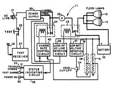
Referring to the simplified functional block
diagram of ~igure 3, the emergency lighting unit 11 is seen
to include qenerally a power supply 30 operable fro~ the
monitored AC line through the connecting power card 17. As
shown, the AC line connection is completed through test
swltch 23 and test receiver 27. Thus, the connection can be
lnterrupted by user actuation of test switch 23 o~ control
panel 16, or by user actuatlon of test receiver 27 by mean~
of the remot~ test lnitlating tsansmltter unit 12. Either
action has t~e effect of removing AC llne power to power
~upply 30 and thereby initatlng a power 1088 condition
within lighting unit 11. An antenna 31 may be provided in
con~unction ~ith remote te~t re~eiver 27, eitber vithin or
external to housing 15.
Pover supply 30 provi~es, in accordance vith
another a~pect of the invention, both unregulated ~igh
current and regulated low curre~t outputs. The regulated
low current output is connected to a standby battery 32
through tbe ~ormally open contacts of a llghtlng control
132~2~6
relay 33 and an ammeter 25. The normally open contacts of
relay 33 connect battery 32 to flood lamps 13 and 14 of the
head assembly, so that upon energi~ation of relay 33 lamps
13 and 14 are illuminated by battery 32.
When relay 33 is deenergized charging current is
supplied to battery 32 from the regulated low voltage output
of power supply 30. To provide for a higher unregulated
current to battery 32 when battery voltage is low, the bat-
tery is connected to the high current unregulated output of
power supply 30 through the normally-closed contacts of a
charge control relay 34. The normally-open contacts of
relay 34 are connected to a status indicating circuit 35
which causes an appropriate one of indicator lamps 20-22 on
control panel 16 to be illuminated in accordance with the
charging mode of the battery.
The operation of relay 33 is controlled by a loss
of AC line detection circuit 36 which monitors a separate
isolated output of power supply 30 and applies battery
voltage to relay 33 upon loss of the isolated output. Relay
2~ 33 .is further controlled by a low battery voltage detectlon
circuit 37 which monitors the terminal vo].tage of battery 32
by means of a voltage divider network 38 cmd interrupts the
ground return of the relay upon the terrninal voltage of the
battery falling below a predetermined minimum threshold
level. Head cut-off switch 24 is provided in this circuit,
in accordance with another aspect of the invention, to
enable a user to interrupt operation of flood lamps 13 and
-~ 1320246
14 if desired. Thus, relay 33 is energized and the flood
lamps are illuminated by battery 32 upon loss of AC line
voltage by detection circuit 36, and remain illuminated
during such voltage loss until the terminal voltage of
battery 32 as detected by detection circuit 37 results in
relay 33 being deenergized.
The operation of the charge control relay 34 is
controlled by a charge rate control circuit 40 which init-
iates a low charge rate upon the battery terminal voltage as
sensed by a voltage divider 41 rising above a predetermined
maximum threshold level. At this time, the connection to
the high current unregulated output of power supply 30 ls
interrupted and charging continues at the relatively lower
charging rate provided by the voltage regulated output of
the power supply. A connection to the normally-open contact
of relay 34 provides a hysteresis or latching function to
the action of charge control circuit 40 so that the relay
will remain in the low current regulated mode once battery
voltage ha~ exceeded the predetermined maximum threshold,
notwithstanding line voltage variations.
Referring to the simplified electrical schematic
diagram of Pigure 4, power supply 30 may include a
transformer 42 having a primary winding 43 and a pair of
secondary windings 44 and 45. AC line power is supplied to
primary winding 43 through normally-closed contacts 46 of a
relay 47 within test receiver 27, which includes
conventional receiver circuitry 48 powered by the AC line.
X
1~202~6
A conventional fuse 49 is provided in series with the line
connection to protect the system in the event of a
malfunction, and the user-actuated te~t svitch 23 i6
provided in series with the line to faciliate user testing
or simulation of a voltage loss as previously de~cribed.
With this arrangement, upon actuation of test sw.itch 23 or
upon receipt of a test ~ignal by receiver circuitry 48, AC
line power is removed fro~ primary windiQg 43.
To provide a relatively high current unregulated
source for charging battery 32 secondary Yinding 44 i8
connected to the input ter~inal~ of a conventional bridge
rectifier network 50. The negative polarity output terminal
of this network is grounded, and the positive polarity
output ter~inal is connected by a filter capacitor Sl to
ground to provide on an output line 52 a ~ource of
unregulated charging curre~t. An additional i~olated
positive polarity output i~ provided on ~ line 53 by a pair
of dlode~ 54 and 55 connected back-to-bac~ across secondary
wlndlng ~4.
A relatively lov voltage regulated output ~ 8
provided by a second full ~ave rectifier ~etwork 56
connected zcross secondary wlnding 45. She negative
polarity output termlnal of this network i8 grounded and the
positivo polarity output terminal 18 co~ected by a filter
capacitor 57 to ground and to the input of a voltage
rogulator 58. In accordance wlth conventional practlce, a
voltage divlder comprising a fi~ed resi~tor 59 and a
-- 10 --
- 1320246
variable resistor 60 are connected between the output of the
regulator and ground to provide a control voltage for opera-
tion of the regulator. A capacitor 61 connected between the
regulator output and ground provides additional filtering
for the regulated direct current produced by the regulator,
which is available on a line 62. An isolated negative pol-
arity output is developed on a line-63 by a pair of diodes
64 and 65 connected back-to-back across secondary winding
45.
The regulated output of power supply 30 appearing
on line 62 is supplied to battery 32 through ammeter 25, the
normally-closed contacts of relay 33 and a fuse 66 provided
to protect battery 32 in the event of a circuit malfunction.
In the event of loss cf AC line voltage relay 33 is actuated
lS to cause battery 32 to be connected to the parallel-
connected flood lamps 13 and 14. Actuation of relay 33 is
accomplished in this event by application of a direct
current rom battery 32 through NPN transistors 70 and 71 to
the winding 72 of relay 33. In the presence of line voltage
transistor 70 is biased into cut-off by the negative
polarity voltage developed on line 63, which is applied to
the base of the transistor through an isolation resistor 73.
Upon loss of AC line voltage the negative bias is removed,
and a positive bias is applied to the base of the transistor
from battery 32 through a voltage divider comprising
resistors 74 and 75 to drive the transistor into saturation.
A capacitor 76 connected between and base and ground
-- 11 --
.q,~
132~246
provides a desirec time delay to the transition betveen
cut-off and ~atur~ed ~tates of tr2nsistor 70
Tran~istor 71 is normally biased into saturation
ty a positive pola-ity voltage developed by battery 32 In
particular, this i provided by ~cltage divider 38 which i~
~een to comprise a zener dlode 77 and a pair of re~istor~ 78
and 79 connected ~etween the po~itive terminal of the
~attery and ground The voltage c~vi~ion pro~ided by
voltage diYidor 38 i~ such that transistor 71 biased into
~aturatlon 80 lonç as sufficient voltage remains acro~s the
battery to oporate flood l~mps 13 ~nd 14 w$thout harm to the
~attery An additional resistor 8~ connected between the
flood lamps and the voltage div$des modlfies tb- inlmum
thr-shold voltag- l-v-l required to malntain satur~tion in
transl~tor 71 during operatlon of the flood l~ ps by
r-du¢lng the ~ on factor of tk- voltago dl~lder,
~-sultlng ln tho a7pllcatlon of a ~reat-r voltag- for a
given battery ter~nal voltage to transistor 71.
The heac cut-off svltch 24 provlded in series with
the base of tran~i~tor 71 provlde~ an effectl~e lov-current
point at which the oporatlon of relay 33 can be interruptod
~lthout swltchl*g ~ea~y curront lc~d~ Actuatlon of cut-off
wltch 24 resultJ in relay 33 belc~ deenergized, allowlng
the user to termi~ato operatlon of flood lamp~ 13 and 14 in
2S the event of an estended pow-r lo~ whore em-rg~ncy llghtlng
i~ no ~onger required To thl~ ecd, head cut-off switch 24
~ay be bl-6table ~ereby the swltc~ can be actuated by the
- 12 -
~32~2~6
user to remain in an open state for continued non-operation
of the flood lamps.
When relay 34 is not energized the unregulated
output of power supply 30 on line 52 is applied to battery
32 through the normally-closed contacts of the relay.
However, when the terminal voltage of battery 32 rises to a
predetermined threshold voltage, as determined by voltage
divider 41, an NPN transistor 81 is caused to conduct and
the winding 82 of relay 34 is energized by the voltage
regulated output of power supply 30 on line 62. To this
end, the voltage divider 41 connected between the positive
terminal of battery 32 and ground includes a zener diode 83,
a fixed resistor 84 and a potentiometer 85. Depending on
the setting of potentiometer 85, a portion of the battery
voltage is applied to the base of transistor 81 such that
conduction is established through the transistor when the
battery voltage has risen above the threshold level. A
hysteresis or latching function is provided for this
transition by a diode 86 and resistor 87 which apply battery
voltaye present at the norrnally-open contact of relay 34
upon energization of the relay. A back-b:iased diode 88 and
capacitor 89 provide transient suppression at relay winding
82, as does a diode 90 connected across winding 72 of relay
33, Thus, upon the voltage across 'oattery 32 rising to the
predeterrnined threshold level, transistor 81 is biased into
saturation and windiny 82 is eneryized to cause relay 34 to
disconnect the unreyulated relatively hiyh voltaye hiyh
- 13 -
~132a246
eurrent output on line S2 from the battery
An indication of the charging mode of the
emergene~ lighting _ystem is provided by indicator lamps
20-22 In particular, the amber indicator lamp 20,
S indicati~g the pre~ence of AC voltage, i8 oonnected between
line 53 and ground and i~ lighted whenever ~upply 30 is
powered m e operation of th- red indieator lamp 21,
indieating a fast eharge, and the green indicator lamp 22,
lndicating a trickle eharqe, is eontrolled by an NPN
transistor 91 having colleetor and emitter electrodes
eonneete~ aeros~ indieator lamp 21 and its baee conneeted to
the nor~ally open eont-cts of relay 34 by a resistor 92. In
the event of a fast eharge oondition, when relay 34 is not
nerglz-d, translator 91 ia non-¢onduetivo and lndicator
laap 21 la lllu lnat-d through a series-eonneeted reslstor
93 by esrr-nt on llne 53. 81ne- the r-aiatanee of l~mp 21
la ueb higher than tb- r-al~tanee of resl~tor 93,
rel-tlv-ly llttl~ voltag- la doveloped aeros~ the resla~or
and lamp 22 do-~ not llght. Bowever, upon aetuatlon of
r-lay 3~ eoneurr-nt with a triekle ehargo eondltion,
tranalator 91 18 bla~ed into ~aturatlon to shunt lndie~tor
lamp 21 Indieator lamp 22, whieh i8 eonn-eted aero~a
realator 21, now ree-lves the voltage pre8ent on llne 53 and
aeeordlngly 1~ eau~od to illumlnate
Aa ahown ln ~lgur- 5, the remote test functlon may
alte~natively be aeeompllahed by utlllzlng a bi-stable relay
94 enorgized by roeeiv-r cireuits 48. With thls arrange-
- 14 -
`- 1320246
ment, power to the lighting unit is interrupted with al-
ternate actuations of the radio receiver, so that the test
function is initiated with a first momentary RF signal and
terminated with a second momentary RF signal. In this way,
the test function can be actuated as long as desired by the
user. This is particularly useful where optional remote
flood lamps 95 are used at a location distant from the
lighting unit.
As shown in Figure 6, it is possible to have a
test function of fixed duration following a momentary RF
signal by utilizing two relays 96 and 97 and a delay circuit
98. Upon receipt of a momentary RF signal receiver circuits
48 actuate relay 96, which thereafter remains actuated by
reason of an additional pair of contacts connected in a
holding circuit. After a predetermined time period, delay
circuit 98 momentarily actuates relay 97, which opens the
holding circuit of relay 96 and terminates the test period.
While a radio frequency test link has been shown
for remote actuation of the emergency lighting system from a
remote location, it will be appreciated that other types of
wireless test links can be utilized. For example, it would
be possible to substitute an infrared light transmitter unit
for the radio freguency transmitter unit 12 and an infrared
receiver for the radio fre~uency receiver 48 whereby the
same test function could be performed by the user within
line-of-sight of lighting unit 11. In this instance, it is
contemplated that an infrared detector would be rnounted on
X
- 1320246
housing 15, preferably on the front panel thereof, to
provide for reception of the radiated infrared beam.
Also, it is contemplated that an ultrasonic
transmitter could be substituted to transmit an ultrasonic
sound beam which would be intercepted by a conventional
ultrasonic receiver within housing 15 to accomplish the
remote test function. In this case, an ultrasonic trans-
ducer would be mounted on housing 15, preferably on the
front panel thereof, to permit a performance of the test
function within acoustic range of the emergency lighting
unit 11.
The dual-mode charging function provided in of
emergency lighting unit 11 provides optimum protection for
nickel-cadmium and lead acid batteries, which are typically
provided in a sealed configuration requiring minimal
maintenance on the part of the user. By reason of the
relatively high initial charging current such batteries are
quickly brought up to a safe charge level following
di~charge during a voltage loss. ~owever, as the battery
terminal voltage reaches a predetermined threshold level at
which such charging cannot be continued, a constant-voltage
i~ maintained across the battery terminals whereby a
progressively decreasing charge occurs as the battery
continues to approach a fully charged condition. This is
shown in Figure 7, wherein, in the high current mode, upon
initial power up of the lighting unit the voltage 100 across
the battery is seen to rise as the charging current 101
- 16 -
applied to the battery decreases. Eventually a vo~ta Q 4 6
level vl is reached at which relay 34 is actuated to
condition the lighting unit to the low current constant
voltage mode, and the battery voltage is thereafter main-
tained at a constant voltage V2 by a variable charging
current which gradually decreases to a low trickle level.
Thus, as a result of the constant voltage maintained on line
62 by power supply 30 the charging rate tapers off as bat-
tery voltage increases with increasing charge state. This
provides recovery for the battery in a minimal time without
compromising battery longitivity.
In one commercial embodiment of the invention the
flood lamps 13 and 14 of the illumination head and battery
32 are rated at 6 volts. Secondary winding 44 provides 7.5
volts AC, resulting in a voltage of approximately 7 volts on
line 52 with a current ranging from 5 to 7 amperes. Secon-
dary winding 45 provides 11 volts AC at 2 amps, resulting in
a regulated voltage on line 62 of approximately 6.5 volts at
up to 3 amperes. For a lead acid battery, battery capaci-
tieS up to 100 amperes may be provided up to 12-1/2 hours of
illumination in the event of aC power failure. For a nickel-
cadmium battery, battery capacities of up to 60 amps may be
provided to obtain an illumination period of up to 6-1/2
hours.
By reason of the low voltage head cut-off circuit
operation of the lamps is interrupted in the event the
charge state of the battery becomes so depleted during
- 17 -
X
- l32a24~
operation as to risk permanent damage to the battery. This
is done by monitoring the terminal voltage of the battery,
and interrupting the connection to the flood lamps in the
event of the voltage falling below a minimum level. The
provision of a test switch in this circuit provides an ef-
ficient means for interrupting operation of the flood lamps
in the event of an extended loss of AC voltage when emerg-
ency illumination is not required.
While a particular embodiment of the invention
has been shown and described, it will be obvious to those
skilled in the art that changes and modifications may be
made therein without departing from the invention in its
broader aspects, and, therefore, the aim in the appended
claims is to cover all such changes and modifications as
fall within the true spirit and scope of the invention.