Note: Descriptions are shown in the official language in which they were submitted.
132~37~
FN 43439 CAN 5A
POLARIZATION-MAINTAINING OPTICAL FIBER
FOR COUPLER FABRICATION
kground o the Invention
Field of the Invent:Lon
The invention concerns a polarization-maintaining
optical fiber that provides an improved single-mode,
polarization-maintaining fiber coupler or coupler/splitter
(herein simply called "coupler"). The invention also
concerns a method of making the coupler and a mount for the
coupler. The preservation of polarization is especially
important in fiber gyroscopes, interferometric sensors, and
coherent communications.
Description of the Related Art
A single-mode optical fiber typically has a glass
inner core of high index of refraction and a glass jac~et
of low index of refraction. Usually, the diameter of the
`~ core is from 3 to 10 micrometers, and the diameter of the
jacket is 80 micrometers for sensor fibers and 125
micrometers for telecommunications. According to Shibata
et al.: "Fabrication of Polarization-Ma~ntaining and
Absorption-Reducing Fibers," ~ournal of Lightwave
Technology, Vol. LT-1, No. 1, pp. 38-43 (198~):
"The general approach to maintaining linear
polarization in single-mode fibers is to increase
fiber birefringence so as to reduce the power
interchange between polarization modes. Several kin~s
of highly birefringent single-mode fibers have been
demonstrated: fibers with a noncircular core, which
cause birefringence due to nonclrcular geometry
[citing Ramaswamy et al.: 'Polarization
i~
- 2 - ~32~7~
Character1stic6 of Noncircular Core Single-mode
Fibers,' ~pplied Optics, Vol. 17, No. 18, pp 3014-3017
~1978)]; fibers with an elliptical cladding, which
cau~e anisotropic strains in the core [citing
~ama~wamy et al.: '~irefringence in Elliptically Clad
~orosilicate Single-mode Fibers, Applied Optics, Vol.
18, No. 24, pp 4080-4084 (1979) and Katsuyama et al.:
~Low-loss Single Polarization Fiber6,' Electron.
Lett., Vol. 17, No. 13, pp 473-474 (lg81)]; and fibers
with refractive-index pits on bo~h sides of the core
~citing Hosaka et al.: '5ingle-mode Fiber with
Asymmetrical Refractive Index Pits on Both Sides of
Core,' Electron. Lett., Vol. 17, No. 5, pp 191-193
tl981) 1 .~
The Shiba~a publication concerns a birefringent single-mode
fibsr, the silica jacket of which includas two fan-shaped,
diametrically-opposed regions that have been doped to have
a different thermal expansion than does the rest of the
jacket, resulting in anisotropic stress-induced
birefringence in the core. At page 40, the Shibata
publication says these fibers
"were fabricated with jacketing techniques. A
single-mode fiber preform made by the V~D method
lciting Tomaru et al.: 'Fabrication of Single-mode
Fibers by V.A.D.,' Electronics Lett., Vol. 16, No. 13,
pp 511~512 (1980)] was elongated to several
millimeters in diameter. Then, it was put into the
center of a thick-wall jacketing silica tube with
about 15-mm inner diameter. Stress-applying parts
were prepared by a depositing Sio2-s2o3-Geo2 glass
layer in a silica tube via the MCVD method. The rods
prepared by the MCVD method were also elongated to
several millimeters and arranged on both sides o~ the
core rod in the jacketing tube. The remainlng inner
~paces in the jacketing tube were filled with 6everal
commercially available silica rods, for example, four
_ 3 _ ~ ~2Q37~
rods with several millimeters of diameter.- The final
preforms were drawn into fibers by a carbnn-resi6tance
furnace."
A birefringent fiher having similarly-shaped
stress-applying regions as well as an elliptical core is
shown in U.S. Patent No. 4,480,897 (Okamoto et al.).
Figures 6 and 8 of U.S. Patent No. 4,561,~71 (~erkey) also
illustrate the manufacture of birefringent fibers having
diametrically-opposed stress-applying regions separated
from the core.
The Shibata publication says:
"In order to reduce the tran~missions loss, the
stress-applying parts must be sufficiently sep~rated
from the core."
Some earlier patents did not recognize the need for such
separation; see, U.S. Patent No. 4,179,189 (Raminow et
al.) and U.S. Patent No. 4,274,854 (Pleibel). Others such
as U.S. Patent No. 4,478,489 (Blankenship) explain that if
such separation is too small, there will be light
transmission loss due to scattering. The Blankenship
patent says that the separation should be as small ~s
possible and indicates that when the separating material
and the stress~applying regions have the same refractive
index, the minimum radius to the stress-applying regions
can be as small as 1.5 times the radius of the core.
Sasaki: "Long-Length Low-Loss
Polarization-Maintaining Fibers," Journal of Li~htwave
Technology, Vol. LT-5, No. 9, pp 1139-1146 (1987), also
concerns birefringent fiber having two
diametrically-opposed stress-applying regions which it says
should be separated from the core and that the absorption
loss is satisfactorily low when the minimum radius to the
8~ ~ stress-applying regions (r) and the radius of the core ~a)
_ have a ratio of more than 3.4. Figure 7 of the Sasaki
publication illustrates the manufacture of the fiber by
for~ing two pits in the jacket and inserting doped rods
into the pits that provide the stress-applying regions.
- 4 - ~32~3~3
Katsuyama et al.: "Low-1066 Single Polarization
Fibers," Applied Optics, Vol. 22, No. 11, pp 1741-1747,
~1983~, concerns a polarization-maintaining optical fiber
that is similar to that of the above-cited Ramaswamy
publications in that the stress-applying region is
ell~ptical and is the intermediate of three concentric
silica regions that make up the jacket:. The intermediate
region ls made stress inducing by belng doped with ~23~
The Katsuyama publication calls this i.ntermediate region
the "elliptical-jacket." The intermecliate stress-applying
region also is doped with GeO2 in order to make its
refractive index the same as in the inner and outer of the
three concentric regions. Consistent with the above
quotation from the Shibata publication, the Katsuyama
publicat.ion ~xplains that ratio of the "core radius" to the
"clad radius" (i.e., minimum radius to the "elliptical
~acket") must be less than 0.5 to minimize absorption loss.
Three polarization-maintaining optical fibers are
illustrated in U.S. Patent No. 4,515,436 (Howard et al.).
The fiber of Figure 3 has a "highly elliptical inner
cladding layer 32" that may comprise boron-doped SiO2 which
is surrounded by an elliptical "outer cladding layer 34"
that may comprise fluorine-doped SiO2 within a jacket that
apparently is undoped silica. The large ellipticity of the
"inner cladding layer thereby induces a large stress on the
fiber, sufficient to significantly separate the two
polarizations of the fundamental mode" (Column 4, lines
47-50)-
Even though the stress-applying regions of some
of the above-discussed prior polarization-maintaining
fibers, such as that of Fi~ure 3 of the Howard patent, are
not separated from the core, it is believed that all
polarization-maintaining fibers currently on the market
have such a separation and that (as taught in the Katsuyama
publication) the ratio of the radius of the core ~o the
mlnimum radius to the stress-applyLng regions is always
~320~7 ~
less than 0.5 ~typically about 0.2). Otherwise, a large
proportion of light transmitted by the core would be
absorbed by the doped, stress-producing region.
Important applications for
polarization-maintaining fibers require a coupler that
maintalns the polarization. Numerous couplers have been
reported. Villarruel et al.: "Fused Single-mode-fibre
Access Couplers," Electronics Lett., Vol. 17, pp 243-244
(1980~, employs cladding removal by radially etching to
within a few micrometers of the core diameter, but by
removing the stress-inducing regions, this apparently
destroys the polarization-maintaining property. Kawasaki
et al., "Biconical-taper Single-mode Fiber Coupler," Op~.
Lett., Vol . 6, pp 327-328 (1981~, employs fusion and
tapering without etching to produce a biconically-tapered-
fused coupler. In Villarruel et al.: "Polarization
Preserving Single-mode-ibre Coupler," Electronics l.ett.,
Vol. 19, pp 17-18 (1983), etching, fusion and tapering are
combined, with no attempt being made to align the
polarization ax~s of the coupler fibers. Nevertheless, the
polarization was said to be satisfactorily maintained, and
this was attributed to the large inherent birefringence of
the fibers.
Dyott et al.: "Polarization-holding Directional
Coupler Made from Elliptically Cored Fibre Having a D
`Section," Electronics Lett., Vol. 19, pp 601 and 602
(1983), employs a fiber that has an elliptical core and a
cladding that has a D-shaped cross section, with the core
close to the flat side of the D. In order to make a
coupler, a small amount of material is etched from the
surface of both fibers over a short length, and the fibers
are positioned in the bore of a glass tube with the etched
region adjacent and the flats of the Ds facing each other.
The glass tube is heated and pulled to draw down a central
section at which the cores come very close together.
~ n the coupler of Kawachl et al.: "Fabrlcation
of Single-polarization Single-mode-fibre Couplers,"
Electronics Let., Vol. 18, No. 22 (1982), polarization is
- 6 - ~ 3 r2 ~ 3 ~ ~
maintained by fu6ing two side-by-side optical iber~ that
are similar to those of the above-oited Ramaswamy, Birch,
and Shibata publications, the Okamoto and Berkey patents,
and Figure 1 of the ~lankenship patent:. That i6, the
fibers that have diametrically-opposecl stress-applying
regions separated from the core. Polarization is said to
be maintained in any of three possi~le alignments, namely,
when the principal axes of the stress--applying regions of
the two fibers are parallel, collinear, or perpendicular.
Yokohama et al.: "Polarization-Maintaining Fibre
Couplers with Low Excess Loss," Electronics Lett., vsl. 22,
No. 18, pp 929 and 930 (1986), concerns
polarization-maintaining couplers made by fusing two
aligned fibers that alss have diametrlcally-oppssed
~tres6-applying regisns spaced from the csre. As preferred
in the Blankenship patent, the stres-applying regisns and
the surrounding jacket or cladding have the same index of
refractisn. The csupler is made by aligning the
polarlzation principal axis sf two side-by-side fibers,
fusing them together, and elongating a portion of the fused
region "until the prescribed coupler ratio was obtained."
The Yokshama publication reports an "excess 10s5 of less
than 0.1 ds was easily achieved" and that the best value
was 0.03 dB. It also reports polarization cross talk (also
called "polarization extinction coefficient") of less than
-30 d~. ~oth of these values are about an order of
magnitude better than in any coupler that we have seen on
the market.
Pleibel et al.: "Polarization-Preserving Coupler
with Self-aligning sirefringent Fibres," Electronics Lett.,
~ 3 Vsl. 19, pp 825 and 826 (1983), fsrms a coupler from fibers
- which are birefringent by having a highly-doped elliptical
region in the cladding. "The fibre, together with its
acrylate coating, is bent and bonded into a 25 cm radius in
a silica block. One side of the fibre and its coating are
poli~hed away while actively monitoring the light
transmitted through the fibre. When the transmitted light
_ 7 _ ~2~ 7s3
begins to drop, the polishing is stopped, and the two
halves are placed together to check the coupling~ The
process is repeated until the desired level of coupling is
obtained." U.S. Patent No. 4,564,262 (Shaw) concerns a
simllar process, but says nothing about monitorlng llght
transmission during the process.
In U.S. Patent No. 4,632,513 (Stowe et al.),
parallel juxtaposition segments of a pair of single-mode
optical fibers are used together to form a coupler which
0 i6 polariæation insensitive.
Summary of the Invention
The invention provides a polarization-maintaining
optical fiber that can be used to make a
polarization-maintaining single-mode fiber coupler that is
believed to have both substantially less transmission loss
and to be substantially better polarization maintaining, as
compared to any coupler that has appeared on the market.
Furthermore, the polarization-maintaining coupler of the
invention should be significantly less expensive to
manufacture than is any polarization-maintaining coupler
that has appeared on the market.
Like some polarization-~aintaining optical fibers
of the prior art, that of the invention has a jacket with
an index of refraction substantially lower than that of the
core, and the jacket includes an oval stress-applying
region. The novel optical fiber differs from those of the
prior art in that the jacket has a substantially uniform
index of refraction and the stress-applying region
has a thermal coefficient of expansion that
affords to the fiber a birefringence between l x 10-4
and 3 x 10⁻⁴ (preferably from 1 to 2 x 10⁻⁴),
substantially contacts the core, and
has an area less than 10 percent that of the
fiber.
- 8 - ~ 32~3~
~y "substantially contacts" is meant that the
stress-applying region is not separated from the core
either by more than 2 ~m or by more than 80 percent of the
radius of the core. If the stress-applying region were
separated from the core by more than about 2 ~m, it would
be very difficult to attain both a birefringence between 1
and 3 x 10-q and a stress-applying region with an area less
than 10 percent that of the fiber.
A birefringence between 1 and 3 x 10⁻⁴
correspond~ to a range of about 8-3 mm beat length at a
wavelength o 850 mm.
Like conventional polarization-maintaining fibers
that have an oval stress-applying region (see the
above-discussed Katsuyama publication), the novel fiber
preferably is made by chemical vapor deposition (CVD) or
modified chemical vapor deposition (MCVD). secause its
stress-applying region is so small and preferably is
contiguous with the core, the novel fiber can be made in
about half the time required to make a conventional
polarization-maintaining fiber and with far fewer failures.
The novel polarization-maintaining optical fiber
can be converted into a polarization-maintaining coupler of
the invention by the steps of
1) placing two short lengths of the optical fiber
side-by-side,
2) aligning the polariæation axes of the two
lengths,
3) fusing the lengths together, and
4) while launching light into one of the lengths,
drawing the fused lengths until light being
emitted from the lengths reaches a predetermined
relationship, usually when equal light is emitted
from the fused lengths.
When the drawing step 4) is stopped at equal
light output, the fused portion of the resulting coupler is
substantially dumbbell shaped in cross section. In
experimentation to date, the maximum diameter at the
- 9 - ~ 3~
coupler waist has been from 1/3 to 1/2 the original slngle
fiber diameter and from 1.5 to 1.8 times the minimum
diameter through a core. Typically when using optical
fibers about 90 ~m in diameter, the maximum diameter at the
coupler waist has been from 30 to 45 ~m.
In step 3) of the outlined method, the aligned
lengths preferably are heated by an unusually wide torch
(larger than 0.5 cm in diameter) so that there is no need
to move the torch relative to the lengths during the
method. Without moving the torch, the used portion of the
resulting coupler is from about 2 to 3 cm in length. The
unfused ends of the fused lengths of the optical fiber can
then be trimmed to an overall length of about one meter to
provide arms or leads that can easily be spliced
mechanically to conventional polarization-maintaining
fibers. The length of those leads can be further reduced
during splicing.
In spite of the fact that the optical fiber from
which the novel coupler is made is relatively inexpensive
and the process of converting two lengths of the fiber into
a coupler is also relatively inexpensive, the coupler of
the invention is superior in performance to any coupler we
have seen on the market. In about half of the prototype
couplers made to date, all of which had been trimmed to an
overall length of about one meter, the excess loS6 has be2n
les~ than 0.1 d~. In most of the others, the excess loss
has been about 0.3 dB or less. Also, the extinction ratios
of at least half of the prototype couplers are better than
20 d~, whereas the best couplers now on the market are
believed to have extinction ratios in the range from 15 to
20 dB. Testing also has indicated that the prototype
couplers retain their pro~erties better over a wide range
of temperatures ~-40 to 70C) than do the best couplers
now on the market.
The low cost of the novel coupler is due in part
to the ability to form it by a biconically-tapered-fused
process which does not require the etching or polishing
steps that have often been used in the prior art.
lo- ~3~
It is surprising that lower cost, r~duced chance
of failure, and superior perfor~nce can all be achieved at
the same time in the production of prototype couplers of
the invention. It is even more surprising that the
prototype couplers of highest yuality have been obtained
from fibers having a birefringence between 1 and 3 x 10⁻⁴
in spite of the fact that of fibers now on the market,
those that best maintain polarization have birefringences
on the order of 4 to 5 x 10⁻⁴. The prototype couplers of
highest quality have been ~ade from optical fiber, the
stress-applying regions of which provided from 1 to 3
percent of the area of the fiber and was contiguous with
the core.
In making prototype couplers, we have not yet
been able to determine whether ~he major polariza~ion axe~
of the paired lengths of the optical fiber are parallel,
collinear, or perpendicular (see above discussion of the
Kawachi publication). Hence, it can be assumed that in
about half of the prototype couplers, those axes should be
perpendicular and in the other half, either collinear or
parallel. It is believed, but has not heen established,
that in couplers having superior performance, the principal
axes of the oval stress-applying regions have been
collinear or parallel when the paired fiber lengths have
been fused together.
~he oval stress-applying regions of the paired
fiber lengths from which the prototype couplers have been
made were elliptical. To obtain couplers of high
polarization-maintaining quality, the minor axis of the
stress-applying region of the starting fiber can
approximate the core diameter but should not~exceed twice
the core diameter. If the minor axis were substantially
greater, the stress-applying region could not provide le6s
than 10 percent of the area of the fiber and also be
6uf~iciently elongated to af~ord a coupler having high
polarlzation-màintaining quallty. ~or best results, the
2 i~
ma~or axis of the stress-applying region of the starting
optical fiber should be from 25 to 40 ~m when the diameter
of the core is about 5~m.
The Drawing
The invention may be more easily understood in
reference to the drawing, all figure of which are
schematic. In the drawing:
Figure 1 is a cross section through a preferred
optical fiber of the invention;
Figure 2 is a cross section, greatly enlarged,
through a preferred coupler of the invention made rom two
short lengths of the fiber of Figure l; and
Figure 3 is an isometric view, partly broken
away, of a mount for the coupler of Fig. 2.
The optical fiber 10 shown in Figure 1 can be
produced as disclosed in Example 1 helow. ~t has, as
viewed in cross section, a circular core 12 (called
"Layer-3" in Example 1) and a contiguous elliptical
stress-applying region 14 (called "Layer-2" in Example 1),
the minor axis of which is slightly larger than the
diameter of the core. Surrounding the stress-applying
region i~ a thin layer 15 (called "Layer-1" in Example 1)
and an outer jacket 16 that are optically identical to each
other for reasons explained in Example 1 and together
provide the jacket or cladding of the optical fiber 10.
Over the jacket is a resinous protective covering 18.
The coupler 20 of Figure 2 has, as viewed in
cross section, two circular cores 22, each surrounded by an
elliptical stress-applying region 24 and having a
dumbbell-shaped jacket 25. The principal axes of the two
stress-applying regions are parallel to each other.
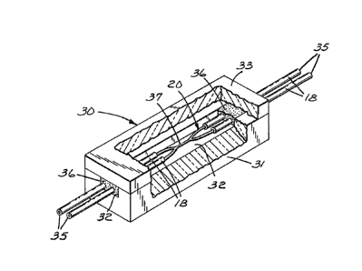
In Figure 3, a mount 30 for the coupler 20 has a
substrate 31 which is formed with a channel 32 that is
enclosed by a cover 33. The substrate and cover should
have approximately the same thermal ~oefficient of
expansion as does the optical fiber 10. Each of the
- 12 - ~ 3 ~ 3~
substrate, cover, and optical fiber preferably i6 quartz
glass. The arms or leads 35 of the coupler are bonded to
the sub6trate and cover by adhesive 36 so that the stripped
area 37 of the coupler is kept out of contact with the
mount and the adhesive contacts only the resinau6
protective coverlng 18. By thus suspending the coupler ~n
air without anything touching the bare glass, the
extinction ratio is much better than it would have been had
there been contact, e.g., if the adhesive 36 had contacted
the bare glass.
In the following examples, all parts are by
weight.
.
Example 1
(making a polarization-maintaining fiber of the invention)
A. Preform Fabrication:
The preform in this example was fabricated by the
modified chemical vapor deposition process (MCVD). In this
process, glass of controlled composition and thickness is
deposited on the inside of a fused silica tube by the
chemical reaction of oxygen with metal chlorides or
bromides. A more complete description of the proces6 may
be found in U.S. Pat. No. 4,217,027 (MacChesney et al.).
A fused silica tube (General Electric #982 WG1~
with an inside diameter of 17.0 mm and an outside diameter
of 20.0 mm was inserted into a deposition apparatus
(preform lathe, gas flow system, hydrogen torch). The
inside wall of the tube was first etched with fluorine to
produce an uncontaminated surface for deposition. Three
layers of glass were then deposited on the inside wall of
the tube. The function and composition of the three layers
is described below.
3~
- 13 ~ 3 ~
Function Composition
Layer-1 Jacket Layer SiO2/P2O5/F
Layer-2 Stress-applying region SiO2/~2O3/GeO2/PzOs
Layer-3 Waveguide core SiO2/GeO2
Between the second clearing pass and the applica~ion of
Layer-3, there was a pre-collapse steE~. Stepwise
conditions were as reported in Table I.
~ 3
/~
~ a o
a~ ~ o o o o o ~ o
~ ~ u. ~ ~ O O ~ U7
~a
m
~ ooooooo
~ a Q u~
O
m a~
~^ ~ O O ~ U) L~
1~ ~ o ~ In Ln ~ co oo u~
.~
4~ In
C~ Q)
~,q ~1
z; ~ ,,~
1 5 '~
~ O o c, o o o ~
O I O ~ ~r o o o o ",
_l ~ ~ ~ ~ tJ
u~
20 .~1''I r~ o
_
~ 1 ~ ~ o~
~ ~ ~
_ ~ a
3 ,1 ~ In .,1
o o a~
Ll U
o 4~
O
_~ O
~ ~ o -' 3 _
~ ~ - .
.~ . Q~ ~
O O O ~ ~J
o o .. , ~ ~
'tn u~ ~ u
~ o
3 o
o ,~
,~
~1
,1 ~ _I r~ ~
o ~ ~ u
Q~ ~ Y ~t
a~ u ~ a~
U~ ~ ~ O
- 15 - ~ 3 ~ ~ 3 ~ 3
Layer-1 was optically identical to the fused
6ilica tube and hence became part of the outer jacket. It
was applied only to permit the core of the
polarl~ation-maintaining iber of Example 1 to have a
diameter of 5 ~m upon drawing the fiber to a diameter of 90
~m.
Temperatures reported in Table I were pyrometer
readings of the external surface of the fused sillca tube.
After completion of the deposition process, the
annular preform was collapsed to a solid rod by standard
techniques.
B. Preform Shaping:
Two diametrically opposed flats were ground
with a conventional surface grinding machine and a diamond
grlnding wheel, removing at each flat 2.13 mm radially.
Then the preform was thoroughly cleaned to remove any
particulate contamination resulting from the grinding.
C. Fiber Draw-
Using a zirconi~ induction furnace, the preform
was drawn into a fiber having a diameter of 90 ~m while
maintaining a temperature sufficiently high to give the
fiber a circular cross-section. To do so, the diameter of
the fiber was continuously monitored in two perpendicular
directions while adjusting the furnace temperature to keep
the diameter the same in both directions. As soon as the
fiber emerged from the furnace, it was coated with a
UV-polymerizable acrylate (950X075 from DeSoto Co.),
exposed to ultraviolet radiation, overcoated with another
UV-polymeri~able acrylate ~3471-2-6 from DeSoto), and
exposed in the same way to provide a resinous protective
cover, then wound up on a reel.
The resulting optical fiber had the following
properties
16 ~3~3~
Length 500 m
Coating OD 205 ~m
Jacket OD 90 ~m
Core diameter 5 ~m
Elliptical stress-applying region
Major axis 27 ~m
Minor axis 7 ~m
Area vs. total area of ~iber 2 %
Attenuation at 850 nmB.0 ds/km
Cutoff 770 nm
Mode Field Diameter at B50 nm 5.9 ~m
H-parameter - 8.1 x 10 6 m
Beat Length at 850 nm 6.4 mm
sirefringence 1.3 x 10
Example 2
(making a coupler of the invention)
Two lengths of the polarization-maintainlng
optical fiber of Example 1 were converted into a coupler of
the invention by the biconically-tapered-fused technique.
Sequential steps were:
a) A 2.8 cm long central portion of each length
of the fiber was mechanically stripped of its dual-layer
acrylate coating and then cleaned chemically.
b) Each length of the fiber was oriented by the
method described in Carrara et al.: "Elasto-Optic Alignment
of Birefringent Axes in Polarization ~olding Fiber", Optics
Letters, Vol. 11, pp. 470-472 (1986). In doing so, an
attempt was made to align the fast and slow principal axes
of the two lengths to be respectively parallel or
collinear, but there was no assurance that the alignments
were not perpendicular.
c) The lengths were held parallel in vacuum
chucks.
d) The two fiber ends on one side of the chucks
were cleaved and placed in optical detection systems.
- 17 - ~ 3 2 ~ ~ a 3
e) Polarized light 850 nm in wavelength was
launched into one of the leads at the other side of the
chucks.
f) The bare sections of the fiber lengths were
pushed together over a length of 2.3 cm, and a UV-curable
adhe~ive was used to bond the ends of the bare section6
together.
g) The central portions of the bare sections
were heated with a stationary hydrogen torch 1 cm in
diameter, thus fusing the fibers over a length of about
0.5 cm.
h) Immediately after the fiber length6 fused
together, the chucks were separated at a rate of 0.2, mm/sec
until their added separation was 10 mm, and then the
separation speed was reduced to about 0.04 mm/sec; this was
stopped and the heat was withdrawn as soon as equal light
output was detected at the optical detection systems. The
cro~s-section at the center of the resulting coupler was as
illustrated in Fig. 2 of the drawing to have:
Maximum diameter at coupler waist35 ~m
Minimum diameter through each core 20 ~m
Minimum diameter centrally between cores 15 ~m
Estimated length of fused portion25 mm
Approximate length of each lead 1 m
i) The coupler was mounted in the channel of a
quartz glass substrate using W-curable adhesive ~as shown
in Eig. 3), and this adhesive was cured by exposure to W
radiation through the quartz cover.
j) The mounted coupler was inserted into
a housing and there potted in a room-temperature-curing
elastomer to provide a hermetically sealed outer protective
package suitable ~or handling and testing as reported
below.
Eleven potted couplers produced as in Example 2
had the following properties:
- lB ~ 2 ~ ~ 7 3
Coupling Excess Loss Extinction Ratio* (dB)
Coupler Ratio (dB) 1-3 1-4 2-3 2-4
A~* 51 0.27 28.2 20.G 28.1 27.3
B 49 0.83 19.4 25.4 27.5 27.7
C ~8 0.31 3l.6 30.4 27.5 30.5
D 55 0.02 23.5 23.8 20.2 20.1
E 47 0.05 32~2 25.6 25.3 28.9
F 51 0.01 28.1 17.5 19.2 27.9
G 54 0.18 21.4 18.8
H 51 0.08 28.0 19.9
I 56 0.08 31.5 26.5 33.5 31.7
J 53 0.25 30.5 20.2 19.9 27.4
X 54 0.01 35.6 2~.0 30.0 33.0
1-3 and 1-4 are polarization extinction ratios for the
uncoupled and coupled output leads, respectively, with
lead 1 as the input; 2-3 and 2-4 are values with lead 2
as the input.
** For Coupler A, Coupling Ratio and Excess Loss were
measured at 820 nm; all other measurements were made at
850 nm.