Note: Descriptions are shown in the official language in which they were submitted.
:~32~
TITLE OF T~IE -tNV~TION
A METHOD FOR DETE~TIN(~. THE MOLDING DEFECTIVENESS
OF A PRESS-MOL~ED ~ORKPIEC~ AND A TERMINAI,
P~ESS-BO~D~NG APPARATUS UTILIZING THE SAME
BACK&ROUND OF '1'~ INVENTION
The present invention rela-tes to a method for
detecting the molding defec-tiveness of a press-mokled
worhpiece, and more particularly, to a molding
defectiveness detec-tlng me-thod adapted for press-
molding work, such as terminal press-bonding of
electric wires, press-fit o-~ heat exchanger pipe~ in
support plates, lid grooving in the end faces of cans
for beer and the like, deep press-drawing, press-
marking, presx-s-tamping, etc., and a terminal press-
bonding apparatus utilizing the aforesaid method.
In a-ttaching a press-bonded terminal to the end of
a covered wire by press-molding, for example, a
covering portion of a certain length is s-tripped from
-the end of a cut wire piece of a prede-termined length,
a wire barrel of the terminal, having a predetermined
shape and dimensions, is press-bonded to a conduc-tor
portion (core portion) at the wire end, and an
insulation barrel o~ the terminal is press-bonded to an
insulatLng-resin-coated por-tion a-t the wire end. Some
of a number of such press-bonded terminals mounted in
this manner may be subject to press-bonding
de~ec-tiveness at -their core portion or resin-coated
portion.
In -these defective terminals, some of cores of the
wire may be le-ft outside the wire barrel ("split-
cored"), the core portion may be wrongly seized by the
insulation barrel ("sunk-cored"), or the covered
~32~7~
-- 2
por-tion of the wire may be seiPed by the wire barrel
("resin-engaged"), for example.
As a method for detec-ting such -terminal press-
bonding defectiveness, a method disclosed in Japanese
Pa-tent Disclosure No. 60-2~6579 is conventionally known
in which the press-bonding state is identified by
detectin~ anything~ unusual during press-bondin~
operation, by means o-f a load sensor. Also proposed in
Japanese Patent Disclosures Nos. 61-161~04, 61-165645,
etc. is a press-bonding defectiveness detecting method
in which the press-bonding state is identified by
visuaL recognition of processed images and the like.
In the former case, however, the unusual situation
during the terminal press-bonding operation is
discriminated by a load level at a certain sampling
time detec-ted by the load sensor, or the maximum load
level detected. It is therefore di~ficult to determine
the type o~ the abnormality, that is, whether the
abnormal terminals are "split-cored" or "resin-engaged"
or anything else. Practically, moreover, some of
abnormal terminals may be regarded as nondeective,
depending on the degree o-~ their abnormality. Thus, it
is hard to accurately determine the abnormality of the
products. In the latter case, on the other hand,
"spli-t-cored" terminals can be discriminated relatively
easily, due to their singularity in shape. It is
generally difficult, however, -to identify "resin-
engaged" or "sun~-cored" terminals, since they hardly
manifest any differences in shape. In determining the
defectiveness of terminals, moreover, it is advisable
to remove defec-tive ones after discriminating them
during the press-bonding opera-tion. Meanwhile, a
press-bonding applicator and other devices are usually
:L320~
-- 3
located above a terminal press-bonding table, so that
-there is no space through wh-ich the press-bonding spo-t
can be surveyed by means of a visual recogni-t:ion
device, such as an ITV camera. ~loreover, the press-
bonding work is performed speedily and continuously.
In consequence, it is difficult to obtain still images
of good quality.
These circumstances are not limi-ted to -the
terminal press-bonding opera-tion L'o:r terminal-bonded
elec-tric wires, and also apply -to the detection of the
molding defec-tiveness of workpieces subjected -to press-
molding work, such as press-fi-t, press-grooving, press-
stamping, deep press-drawing, etc.
OB~ECTS AND SUM~AR~ OF TH~ lNVFNTION
The primary object of the present invention is to
provide a method for securely detecting the molding
defectiveness of a press-molded workpiece wi-th ease and
in a short period of time.
Another object of the presen-t invention is to
provide a method for securely detec-ting the press-
bonding defectiveness of a terminal of a terminal-
bonded wire with ease and in a short period of time,
and a -terminal press-bonding apparatus utilizing the
method .
~ till another object of the present invention is
-to provide a method cap~ble of discriminating various
press-bonding defectiveness pat-terns produced during
press-bonding of a -terminal Oe a -termina.l-bonded wire
so -that.-the press-bonding defectiveness of the terminal
can be securely detected, and a terminal press-bonding
appara-tus utilizing -the me-thod.
According to -the presen-t inven-tion, there is
~ 3 ~ 5 ~
provided a method for detecting -the moldi.ng
defectiveness of a press--molded workpiece, which
comprises steps of detecting a time-based prof:ile o:f a
molding load acting on the workpiece during press-
molding opera-tion, comparing -the detec-ted molding load
profile wi-th a reference molding load profile, and
determining the molding defectiveness of -the workpiece
in accordance with the result of -the comparison.
According -to an aspect of the presen-t invention,
there is provided a press-molding defectiveness
detecting method adap-ted for the detection of -the
press-bonding defectiveness of a terminal which,
including a wire barrel and an insulating barrel, is
at-tached to the end of a covered wire so that the wire
barrel and the insulation barrel are press-bonded to an
e~posed conductor portion at the end of the covered
wire and a covered port.ion of the covered wire,
respectively, by press-molding.
A time~based profile of a press-bonding load
acting on the terminal during terminal press-bonding
operation is detected, and the detected press-bonding
load profile is compared with a reference press-bonding
load profile, whereby the press-bonding defectiveness
of the terminal is de-termined.
As required, the integral value of the press-
bonding load acting on the terminal may be calculated
on -the basis of the detected press-bonding load profile
so -that the press-bonding defectiveness oP the terminal
can be determined by comparing -the calcula-ted integral.
value with a predetermined reference value.
Alterna-tively, a plurality of press-bonding load values
at predetermined points of time may be recorded on the
basis of the detected press-bonding load profile so
- 5 - ~ 132~7~
that the individual press-bonding load values are
compared with predetermined reference values
individually corresponding thereto, and that the press-
bonding defectiveness of the terminal can be determined
in accordance with the individual results of -the
comparison. Alternatively, moreover, a press-bonding
load value at at least one predetermined point of time
and the maximum press-bonding load value may be
recorded on the basis of the detected press-bonding
load profile so that the individual press-bonding load
values are compared with prede-termined re~erence values
individually corresponding thereto, and tha-t the press-
bonding defectiveness of the terminal can be
de-termined. Furthermore, profiles of press-bonding
loads acting on the wire barrel and the insulation
barrel during the press-molding may be detected
separately so that the detected press-bonding load
profiles are compared with reference press-bonding load
profiles individually correspondin~ thereto, and that
the press-bonding defectiveness of the terminal can be
determined.
According to`the present invention, moreover,
there is provided a terminal press-bonding apparatu~
constructed so that a terminal is placed on a terminal
press-bonding -table, and is press-molded by means o~ an
applicator, which is driven by means of a drive unit,
whereby the terminal is attached to the end of a
covered wire so that a wire barrel and an insulation
barrel of the terminal are press-bonded -to an exposed
conductor portion a-t the end of the covered wire and a
covered portion of the covered wire, respectively. A
couplin~ member is disposed between the drive unit and
-the applicator and coupled directly to the applicator.
a~s
- ~ -
Sensor means, which is alttached -to the coupling member,
serves to detect a -time-based profile of a press-
bonding load acting on -the terminal during -the terminal
press-bonding operation. Discrimination circui-t means
serves to compare the press-bonding load profile
detec-ted by the sensor means with a reference press-
bonding load profile, thereby de-termining the press-
bonding defectiveness o~ the -terminal.
Preferably) -the coupling means includes a neck
portion narrower in cross-sectional area than any o-ther
portion thereof, the sensor means being attached to the
neck portion.
Preferably, moreover, trigger means is used -to
detect the point of time for the s-tar-t of the press-
bonding operation by means of the applica-tor and
deliver a trigger signal 3 and the discrimination
circuit means starts reading the press-bonding load
profile, de-tected by -the sensor means, on termination
of a predetermined period of time after the delivery of
the trigger signal from the tri~ger means.
The above and other objects, features, and
advantages of -the invention will be more apparent from
the ensuing detailed description taken in connection
with the accompanying drawings.
BRIR~ DESCRIPTION OF THE DRAWINGS
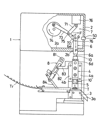
Fig. 1 is a cutaway front view showing an
embodiment of a terminal press-bonding apparatus to
which is applied a method for detecting the press-
bonding defectiveness of a terminal-bonded wire
according to the present invention;
Fig. 2 is a partial plan view of a -terminal train
Tr fed to the terminal press-bonding apparatus shown in
:~3~07~8
-- 7
Fig. 1;
Fig. 3 is a side view of the -terminal train Tr
shown in Fig. 2;
Fig. ~ is a plan view showing a sta-te such that a
press-bonded terminal is normally a-t-tached to the end
of a covered wire;
Figs. 4B, 4C and 4D are plan views showing various
states such that press-bonded -terminals are attached
defectively;
Fig. 5 is an enlarged view of the principal part
of a ram 6 of the terminal press-bonding appara-tus
shown in Fig. 1, illus-trating in detail the way a load
sensor is mounted;
Fig. 6 is a circuit diagram illustrating the
connection of the load sensor shown in Fig. 6;
Fig. 7 is a block diagram showing the internal
configuration of a pattern discrimination circuit for
de-termining the mounting defectiveness of press-bonded
terminals;
Figs. 8A to 8F are graphs schematically showing
-the patterns of various press-bonding load signal
waveforms detected when a terminal is press-bonded to
an electric wire having seven cores;
Figs. 9A to 9F are graphs schematically showing
the patterns of various press-bonding load signal
waveforms detected when a terminal is press-bonded -to
an electric wire having sixteen cores;
Fig. ~0 is a program flow chart of a defec-tive
-terminal discrimination rou-tine executed by means o~ a
microcomputer (MCU) 26 shown in Fig. 7;
Figs. llA to llD are graphs schema-tically showing
the pat-terns of various press-bonding load signaL
waveforms detected when the cores ot` a 7-core electric
- 8 - ~ 7~)
wire are press-bonded to a half of a wire barrel of a
terminal;
Figs. 12A -to 12D are sectionnl views schematica11y
showing terminal press-bonding s-tates corresponding to
-the press-bonding load s-ignal wave-~orm patterns shown
in Figs. lIA to llD, respec-tively;
Fig. 13 is a side vlew of a terminal press-bonding
apparatus in which an insulation barrel and a wire
barrel of a terminal is press-bonded by means of
separate pressing knife edges;
Fig. 1~ is a partial enlarged view showing the way
a load sensor is mounted on a kni~e edge 5A f'or the
wire barrel shown in Fig. 13;
Fig. 15 is a partial enlarged view showing the way
a load sensor is mounted on a knife edge 5B for the
insulation barrel shown in Fig. ~3;
Fig. 16 is a block diagram showing the internal
configuration o~ a pattern discrimination circuit for
determining the press-bonding de~ectiveness of the
insulation barrel and the wire barrel when the barrels
are press-bonded independently;
Figs. 17A to 21A are graphs schematically showing
the patterns of various presx-bonding load si~nal
waveforms de-tected when the wire barrel is press-
bonded;
Figs. 17B to 21B are graphs schematically showing
the patterns of various press-bonding load signal
waveforms detected when the insulation barrel is press-
bonded;
Fig. 2~ is a graph showing press-bonding load
signal waveforms read with dif'ferent t;mings at the
-time of' detection of the -terminal press-bonding load;
Fig. 23 is a block diagram showing the internal
9 ~32~73~
configura-tion of a pattern discrimination circuit
having a sensor 50 for detecting the start of press-
bonding operation;
Fig. 24 is a partia] sectional view showing a
state such that a pipe is press-fit-ted in-to a support
plate of a heat exchanger;
Figs. 25, 26 and 27 are graphs schematically
showing the patterns of various press--fit load signal
waveforms detected when the pipe of the heat exchanger
shown in Fig. 24 is press-fitted,
Fig. 28 is a partial sec-tional view showing the
way conduc-tors are connected by means of a sleeve;
Fig. 29 is a graph schematically showing the
patterns of press-bonding load signal wave~orms
detected when the sleeves shown in Fig~. 28 are press-
bonded;
Fig. 30 is a partial sectional view showing a
punch and a substrate to be press-marked;
Fig. 3t is a graph schematically showing the
pa-tterns of press-bonding load signal waveforms
detected when the punch shown in Fig. 30 is used for
press-marking;
Fig. 32 is a partial sectional view showing a
punch and a workpiece to be subjected to deep press-
drawing;
Figs. 33 and 34 are graphs schema-tically showing
the patterns of press-honding load signal wave~orms
detected when -the punch shown in Fig~. 32 is used for
deep press-drawing;
Fig. 35 is a partial sectional view showing a
punch and a workpiece to be press-stamped; and
Fig. 36 is a plan view showing the end face of a
can with a lid groove.
~2a7~
-- 10 --
~TAIL~D D~SCRIPTI~N
Fig. 1 shows a terminal press-bonding apparatus 1
for effec-ting -the me-thod according -to the present
invention. The apparatus l comprises a press frame 2,
a terminal press-bonding -table 3 a-t-tached -to the press
frame 2, an applicator 4 disposed above the table 3 so
as to be vertically movable along guide -frames 4a and
4b, and a pressing portion 5 for -terminal press-bonding
a-ttached to -the lower end of the applica-tor 4. The
press-bonding apparatus 1 further comprises a ram
(coupling member) 6, which is sli.dably passed through a
hole 2b in a center frame 2a of the press f'rame 2, a
toggle unit 7 -for vertically moving -the ram 6, and a
terminal feeding lever 8.
The toggle unit 7 includes an upper link 71, a
lower link 72, a toggle 73, and a flywheel 74. One end
of each of the links 71 and 72 and -the toggle 73 is
rockably moun-te~ on a shaf-t 75. The other ends of the
upper and lower links 71 and 72 are supported by a
fixed portion 76 and the upper end of the ram 6~
respectively, for rocking motion. The other end of the
toggle 73 is rotatably supported by the peripheral
portion of the flywheel 74. The flywheel 74 is rotated.
by means of a motor (not shown~, and its rotation is
transmit-ted to the ram 6 throu~h -the to~gle 73 and the
upper and lower links 71 and 72. Thus, the ram 6 is
reciprocated vertically.
The upper end of the -terminal feeding lever 8 is
rockably mounted on a shaft 81. One end of an arm 83
is fi~ed to the upper end of the applicator 4. The
other end of the arm 83 is fitted in a drive groove 82
which is formed in -the central portion o~ the lever 8.
A rod 84 is attached to -the lower end of the lever 8.
3 2 ~
The -terminal -feeding lever 8 is swun~ from side to side
by the vertical motion o-f the applicator 4, thereby
driving the rod 84 hori~on-tally. As a result, a number
of terminals T, arranged in -the form of a continuous
-terminal -train Tr, are fed one by one onto -the terminal
table 3. Electric wire end portions are discharged
through a tray 3a a~ter they are fi-t-ted individually
with the terminals T.
Figs. 2 and 3 shows -the terminal train Tr in which
a number of terminals T, each i~ormed of a conduc-tive
me-tal pla-te, are coupled by means o-~ a carrier Tc.
Each terminal T is composed of a wire barrel T2, an
insulation barrel Tl, a con-tac-t terminal portion T3,
e-tc. The terminal train Tr is fed to the terminal
press-bonding apparatus 1, and the individual -terminals
T are cut off from -the carrier Tc. Then, the wire
barrel T2 is press-bonded to cores W2 at the end of its
corresponding electric wire W, while the insulation
barrel T1 is press-bonded to an insulating-resin-coated
portion W1, as shown in Fig. ~A mentioned later.
When the pivotal point (corresponding -to the shaft
75) of the upper and lower links 71 and 72 is pressed
by the toggle 73, in the toggle unit 7, the links 71
and 72 are urged to be aligned. The more closely the
alignmen-t line resembles a s-traight line, the grea-ter a
vertical ~orce P acting in -the longi-tudinal direction
of the links 71 and 72 will be. If the links 71 and 72
are equal in length, -the force P o~ -the link 72 to
depress the ram 6 is given by
P = F/(2tan ~),
where ~ is the angle formed between a vertical line and
the link 72, and F is the urging ~orce of the toggle
75.
~ ~2 - ~32~
The force P is a -force (hereinafter reeerred -to as
press-bonding load) with which the pressing portion 5
for terminal press-~onding presses -the ter~inals T on
the terminal table 3. Thus, the ram 6 is subjec-ted to
a reaction force P) (= P~ agains-t the press-bonding
load P when -the terminals are press-~onded. Thereupon,
the reaction force P' ac-t;ing on the ram 6 is detec-ted.
The ram 6 hax a slerlder neck portion 6a which is
formed by rectangularly cutting a predetermined
portion, e.g. t the lower portion, of -the ram body over
the whole circumference thereof, as shown in Figs. l
and 5. The ram 6 is coupled to the applicator ~ in a
manner such -that its lower end 6d is removably fitted
in an engaging groove 4a formed a-t the upper end
portion of -the application ~. An upper end 6e of the
ram 6 is rocka~ly coupled to the o-ther end of the lower
link 72 by means of a coupling pin 76. ThusJ the ram 6
serves -to connect the applica-tor ~ and the link
mechanism of the toggle uni-t 7. A load sensor 10 is
attached to the neck por-tion 6a of the ram 6.
The load sensor 10 is composed of a pair of sensor
elements 11 and ll', which are provided on a front
surface 6b and a reverse surface, respectively, of the
neck portion 6a. The sensor element ll is formed, for
example, of two s-train ga~es ~strain resistance
elemen-ts) or load cells 12 and 13. The load cells 12
and 13 are arranged at right angles to each o-ther. The
load cell 12 is pas-ted on the neck portion 6a alon~ the
axial direction ~longitudinal direction) thereo-f, and
the o-ther load cell 13 is pasted at right angles
(-transverse) to -the axial direc-tion. The resistance
value of the load cell 12 varies depending on the
longitudinal contraction (or s-train) of the neck
~32~8
- 13 -
por-tion fia, as indicated by arrow ~A'. The resistance
value o~ the load cell 13, on -the o-ther hand, varies
clepending on -the transverse e~tension (or strain) of
-the neck por-tion 6a, as indicated by arrow B~'.
Like the sensor elernen-t 11 on the fron-t surface 6b
of the neck por-tion 6a of the ram 6, the sensor element
11' on the reverse side of the neck portion 6a is
composed of two strain gages or load cells 12' and 13',
and is pasted substantially corresponding in position
to -the sensor element 11.
The load sensor 10 detects the reac-tion force
against the press-bonding load on the ram 6 by
detecting the strain produced in -the neck portion 6a of
the ram 6 during terminal press-bonding operation by
means of the ram 6. Since the neck portion 6a i5
narrower than any o-ther portion of the ram 6, -the
reaction force produced in the ram 6 durin~ the press-
bonding opera-tion can be detected very accurately and
with high sensitivity by detecting the strain of the
neck portion 6a. The ram 6, which is a coupling member
removably coupled to the applicator 4, need not be
replaced, although the applicator is replaced depending
on the types of the terminals and -the electric wires.
Accordingly, the load sensor 10 can be left unremoved
on the ram 6, thus ensuring improved operatin~
efficiency.
As shown in Fig. 6, the load cells 12, 13, 12' and
13' of the sensor elements ll and 11' of the load
sensor 10 are connected to a bridge circuit. Junctions
a and _ between the load cells 12 and 12~ and between
the cells 13 and 13' are connected to a power source
l~, while junctions c and _ between load cells l2 and
l3 and between cells 12' and 13' are connected to
32~8
terminals lOa and lOb, respeotively.
The -terminals 10a and lOb of the load sensor 10
are connected to the inpu-t terminal of a strain
amplifier 21 of a pattern discriminati.on circuit 20.
The output -term.inal of the strain amplifier 21 .is
connected to the re~qpect:ive input terminals of an
analog-to-digital converl;er (hereinafter referred to as
A/D conver-ter) 22 and a comparator 23. The output
terminal of the comparator 23 :is connected to -the
trigger input terminal of the A/D converter 22. The
output -terminal of the converter 22 is connected to a
microcomputer (hereinafter referred -to as MCU) 26 which
comprises a memory 2~, a central processing unit
(hereinafter referred to as CPU) 259 etc.
The operation of the terminal press-bonding
apparatus will now be described.
The toggle 73 and the upper and lower links 71 and
72 of the toggle unit 7 convert the rotation of the
flywheel 74 into reciprocation of the ram 6, thereby
causing the applicator 4 to reciprocate. As the
applicator 4 reciprocates in this manner, -the terminal
feeding lever 8 swings from side to side, thereby
feeding the terminals T from the terminal train Tr one
by one onto the -terminal press-bonding table 3 with the
aid of the rod 84. At the same time, the electric wire
W is fed to the table 3 so that the coated end portion
W1 and the cores W2 are pu-t on the insulation barrel Tt
and the wire barrel T2, respectively) of each
corresponding terminal T.
After the electric wire W is put on the terminal
T, the pressing portion 5 attached to the lower end of
the descending applicator 4 presses the -terminal T
which, along with the end of the wire, is placed on the
207~
terminal press-bonding -taLble 3. When the terminal 'I' is
pressed in this manner, the ram 6 is subjected to a
reaction force, so tha-t a s-train is produced in -the
necl~ portion 6a. The load sensor 10 detects the strain
in the neck portion 6a, and delivers an electrical
signal (strain signal) V indicative of` the de-tected
strain.
The signal V delivered from -the load sensor 10 is
amplified by the strain amplifier 21, and -t,hen applied
to the A/D converter 22 and the comparator 23. The
comparator 23 compares the inpu-t signal V and a
reference signal Vs. If V > Vs is de-tecte~, the
comparator ~3 delivers a trigger signal Pt, thereby
subjecting the A/D converter 22 -to a level trigger. On
receiving the trigger signal Pt, the A/D converter 22
starts sampling, and performs A/D conversion of the
input signal V. Then, the waveeorm of the input signal
V is stored successively in the memor~ 24 of the MCU
26. The reference signal Vs of the comparator 23 is
adjusted to a predetermined voltage level such tha-t the
leading edge of a common wave~orm (mentioned later),
produced at the time of terminal press-bonding, can be
sei~ed. Those signal~ whose level is higher than the
predetermined level are all sampled.
The sampling period of the waveform of the signal
V varies depending on -the operating time of the press
used. In this embodiment, the press-bonding period is
about 0.8 sec, and -the press-bonding time is about 80
msec. If -the waveform of the signal V is divided into
about 400 equal par-ts, therefore, it can enjoy a
satisfa,ctory reproducibility. Thus, the sampling
period used is about 200 ~sec.
The CPU 25 previously stores therein the signal
7 ~ 8
- 16 -
wave-form (hereinafter referred to as normal wave-form)
in a normal press-bonding state, which is stored in -the
memory 24. The CPU 25 compares the stored normal
waveform with each waveform obtained at the time of
each terminal press-bondino cycle, thereby determining
whether the obtained waveform is norrnal or not. If the
CPU 25 judges the wave~orm to be abnormal, it delivers
an abnorma]ity discrimination signal VO.
Figs. ~A -to 4D show various s-ta-tes of press-
bonding in which the -terminal T is press-bonded -to the
electric wire W by means of -the terminal press-bonding
apparatus 1. Fig. 4A shows a state such that the
terminal T is normally press-bonded by the apparatus 1.
When the terminal T is normally bonded to the end of
the wire W, the insulation barrel T~ of the terminal T
securely holds the insulated portion W1 of the wire W
so as to cover the whole periphery thereof and be
situated at a narrow distance Erom the end edge of the
insulated portion Wl. The wire barrel T2 securely
holds the cores W2 so as to cover the whole periphery
thereof.
The terminal T cannot be normally press-bonded -to
the electric wire W in various cases. Figs. 4~, 4C and
4D typical exa~ples of such cases. In Fig. 4B, some of
the cores W2 are wrongly situated outside the wire
barrel T2 I''split-cored''). In Fig. 4C, the cores W2
are held by the insulation barrel Tl of the terminal T
~"sunk-cored"). In Fig. 4D, the insulated portion Wl
is held by the wire barrel T2 ("resin-engaged").
AcGording to the present invention, these defective
sta-tes of press-bonding, which are to be eliminated,
are detected as follows.
Figs. ~A to 8F and 9A to 9F show examples of
~20~
- 17 -
signal waveform pat-terns obtained at the time of
terminal press-bonding. In the cases shown in Figs. 8A
to 8F, a vinyl-coated wire (AVS 0.5 SQ; 7 cores) is
used as the electric wire to be press-bonded to the
terminal. In -the cases shown in Figs. 9A to 9F, a
vinyl-coated wire (AVS 1.25 SQ; 16 cores3 is used for
the purpose. ~n these drawings, which illustrate time-
based transitions of the press-bonding load, full lines
represent normal waveforms, while dashed lines
represent defectlve wave~'orms.
Figs. 8A and 9A show the normal signal waveforms
obtained in the normal press-bonding state. The
waveforms indicated by the dashed lines in Figs. 8B,
8Cl 9B and 9C are typical examples of waveforms
peculiar to "split-cored" press-bonded terminals. Fig.
8B is indicative of a case such that two out of seven
cores are disengaged from the wire barrel T2 (this
s-tate is indicated by "2/7" in Fig. ~B, and the same
applies hereinafter), while Fig. 8C is indica-tive of a
case such that five out of the seven cores are
disengaged from -the barrel T~ /7"). Fig. 9~ is
indicative O-e a case such tha-t four out of sixteen
cores are disengaged from -the wire barrel T2 ("~/16"),
while Fig. 9C is indicative of a case suoh that twelve
out of the sixteen cores are disengaged erom the barrel
T2 ("12/16"). As seen from -these waveeorms, the peak
level of the press-bonding load depends on the number
Oe disengaged cores. Thus, the acceptability of each
terminal can be determined by obtaining the level
difference be-tween its waveform and the waveform (Fig.
~A or 9A) of -the normal terminal (Fig. ~A).
For the "resin-engaged" terminals, the pa-tterns Oe
the press-bonding load have distinctive features.
- 18 _ ~3~7~8
There are substantial differences between these load
patterns and those of the normal waveforms indioa-ted by
the full lines, during t:he period between the points of
time of 15 msec and 30 msec after the start of -the
press-bonding operation, as indicated by the dashed
lines in Figs. 8D, 8E, 9D and 9~. More specifically,
the press-bonding load o:f the "resin-engaged"
terminals, durin~ this period, is much greater -than
that of the normal terminals. Thus, -the "resin-
engaged" terminals can be discriminated by detecting
the press-bonding load during the period between the
time points of 15 msec and 30 mseo after -the start of
the press-bondin~ operation, and comparing the detected
load with the press-bonding load of the normal
terminals. If the defective terminals are fully
"resin-engaged", the increased press-bonding load tends
to drop sharply in the middle of the press-bonding
operation, as indicated by the dashed lines in Figs. 8D
and 9D.
~or the "sunk-cored" terminals, the peak levels of
the press-bonding load waveforms and the load levels
near the time point of 25 msec are considerably
different from those of -the normal terminals, as
indicated by the dashed lines in Fi~s. 8F and 9F.
Thus, the defectiveness of each -terminal can be
determined by de-tecting the differences in these
levels.
In the press-bonding patterns of the defective
terminals (indicated by the dashed lines in Fi~s. 8B to
8F and 9B to 9F), the difference (t2 - tl) between time
tl for the peak of the waveform obtained when the
terminal is cut off and time t2, at which the same load
level as the peak level is attained next with the
:L32~
-- 19 --
terminal press-bonded, is smaller or greater than that
for -the waveform patterns ot the normal terminals
indic~-ted by the full lines. The former is smaller
than the latter for the "resin--engaged" terminals,
while the former is greater -than the lat-ter for the
"spli-t-cored" or "sunk-cored" terminals. Thus~ the
defec-tiveness of eaoh -te;rminal can be also determined
by storing time tl, as a reference point for the
comparison, and then de-tecting time t2.
As described above, the defectiveness of those
"split-cored" -terminals which include many dislocated
cores and "sunk-cored" terminals can be determined by
the level of the press-bonding load, while tha-t of the
"resin-engaged" -terminals can be determined by the
change o-f -the pa-ttern in the middle of the press-
bonding operation. Also, the degree of the
defectiveness can be identified by examining the peak
level during the press-bonding operation.
Fig. 10 shows an example of a defective terminal
discrimination program which is executed by the pat-tern
discrimination circuit 20. First, the MCU 26 of the
circuit 20 waits until the trigger signal Pt is
delivered from the comparator 23 (step Sl). In the
comparator 23, the press-bonding load signal V inputted
through -the strain amplifier 21 and the reference
signal Vs is compared. If -the load signal V is higher
in level than the reference signal Vs, the trigger
signal Pt is outputted. The MCU 26 waits repeating
step S1 until the trigger signal Pt is outpu-tted. When
the tr;gger signal Pt is delivered from the comparator
23, a pressure-bonding load profile is read. The
timing for -the reading of the press-bonding load
profile is kept constant by means of the trig~er signal
- 2n - ~32
P-t.
The press-bondin~ load signal V is sampled from
-the read pro-file, a press-bonding load VTs at time -t2
is s-tored, and a maximum level Vps of -the press-bondin~
load signal V is detected and stored (step S3). As
shown in Fig. 8A or 9A, -time t2, which i~ set in
accordance wi-th a number of empirical data, is the
point of -time when the press-bonding load of the same
level as the load ob-tained at time -tl when -the -terMinal
T is cut off from the terminal train Tr, durin~ the
normal terminal press-bonding opera-tion, is ob-tained.
Then, differences ~VT (- VTC ~ VTS~ ~nd ~p (~ VpG
- Vps) be-tween the values VTs and Vps sampled in step
S3 and their corresponding reference values VTG and VpG
are calculated (step S5). The reference values VTG and
VPG are the press-bonding load ob-tained at time t2 and
the maximum level, respectively, o-f the normal press-
bonded terminal. These values are previously stored in
the memory 24. The MCU 26 de-termines the defectiveness
of the terminal by the calculated differences AVT and
~Vp. Thus, whether the difference ~VT is smaller than
a predetermined negative discrimination value AV~o is
determined in step S7, and whe-ther the difference ~VT
is greater than a predetermined posi-tive discrimination
value AVpo is determined in step S9. If the re~pective
conclusions of these steps of discrimination are both
NO, it is concluded that the -terminal has been press-
bonded normally (step S11). If -the conclusion of step
S7 is YES, the -terminal is judged to be "resin-engaged"
(step S13). If the conclusions of steps S7 and S9 are
NO and YES, respec-tively, the terminal is judged -to be
"split-cored" or "sunk-cored" (step S13~. If a
defective -terminal is detected, -the MCIl 2~, proceeds to
:~ 3 2 ~
- 21 -
step S17, and delivers -the abnormali-ty discrimina-tion
signal VO. Thus, -the defective -terminal discrimination
is finished, and the program returns to step Sl,
whereupon the same discriminating operation is repeated
Eor the individual terminals.
The abnormali-ty disorim:ination signal VO de]ivered
from the MCU 26 of the pattern discrimination circuit
~0 is supplied to an alarm device, such as an alarm
lamp, which informs an opera-tor of abnormal -terminal
press-bonding. Usually, the automatic terminal press-
bonding apparatus is cons-truc-ted fiO that terminal-
connected electric wires are automatically tied up in
bundles of regular quantities ~e.g., 100 to 200), and
are delivered from the appara-tus by means of a conveyor
mechanism. Therefore, those bundled wires which are
judged to be abnormal by the abnormalitY discrimination
signal VO, at the time of the delivery, may be
discharged separa-tely. In this manner, wires with
defective terminals can be preven-ted ~rom being fed to
the next step of operation.
The abnormality discrimination signal is delivered
for each type of abnormality, and a counter is used to
count abnormal wires or deFective terminals for each
type and display the count ~alue. By doing this, the
troubles or defective spots of -the terminal press-
bonding apparatus can be detected. If -the count number
of "resin-engaged" -terminals is extremely large, then a
wire stripper For s-tripping the wires is in trouble.
I-F the count number of "spli-t-cored" -terminals is
large, then it may be concluded that the press-bonding
positions of the terminals are wrong.
I~' the dislocation oF only one or two cores oF
each "split-cored" terminal, as shown in Figs. 8B or
:~3~7~
- 22 -
9B, is put in question, -the maximum permissible limit
of -the variation of the press-bonding load profile of a
normal terminal ought to be narrowed oonsiderably,
since the profile of the press-bonding load of -the
defective terminal differs only slightly from that of
the normal terminal. It is therefore difficult -to
cliscrimina-te the abnorma:Lity.
Let it be supposed, for example, that a wire
including seven cores and having a cross-sectional area
of 0.~ mm2 is press-bonded -to a terminal. If all -the
cores W2 are press-bonded -to a left-hand half T2a of
the wire barrel T2 of the terminal T, as shown in Fig.
12A, the resulting product is regarded as normal. In
Fig. 12B, one of the cores W2 is bonded to a right-hand
half T2b of the wire barrel T2. In Fig. 12C, two of
the cores W2 are bonded to the right-hand half T2b. In
Fig. 12D, moreover, one of the cores ~2 is attached to
-the righ-t-hand half T2b, while another is in the center
of the wire barrel T2, that is, on the boundary between
-the left- and right-hand halves T2a and T2b. The
si-tuations shown in Figs. 12B, 12C and 12D entail
various abnormal press-bonding conditions.
Those cores inside the right-hand half T2b of the
wire barrel T2, as shown in Figs. 12B to 12D, canno-t be
press-bonded to the wire barrel T2. In these cases,
therefore, the terminal can practically be regarded as
"split-cored." Having the cross-sectional area of 0.5
mm2 or thereabout, these cores for each -terminal cannot
be large in number. Accordingly, -the capacity for
current flowing through the press-bonded por-tion can be
greatly influenced by the dislocation of only one or
-two cores. In the case of a wire which includes a
relatively large number of cores and has a cross-
~0~3
- 23 -
sectional area of 1.25 mm2 or mo:re, the curren-t
capaci-ty cannot be influenced by -the dislocation of one
or two cores, and cannot -therefore en-tail any
defectiveness in press-bonding.
The press-bonding defectiveness of those wires
with a relatively small number of cores, among which
one or -two cores are dislocated~ and whose press-
bonding load pro~ile differs only slightly from tha-t o~
normal products, can be detected in -the following
manner.
A reaction force acting on the press, during -the
terminal press-bonding operation, is detec-ted, and the
sum -total of the press-bonding loads is obtained. ~lore
speci~ically, the time-based transition of the reaction
force is obtained, and -the integral value o-f the
reaction force is calculated. The press-bonding
defectiveness and its type can be discriminated by the
calculated integral value of the reaction ~orce. Thus,
~he press-bonding defectiveness o~ the terminal can be
detected and classi~ied accurately and speedily.
More specifically, the microcomputer 2~ adds
voltage values corresponding -to wave~orms input-ted from
the A/D conver-ter 22, in accordance with a time series,
for -the individual sampling cycles, thereby obtaining
the sum -total. The resulting sum total is compared
with that for the normal product If the former is
smaller than the latter, the terminal concerned is
regarded as defective. Thus, the discrimination
circuit 20 prepares pat-terns of the time-based
-transitions of -the press-bonding loads detected by the
load sensor 10, as shown in Figs. llA to llD. The
press-bonding defectiveness and its -type are
discriminated by the integral values of the patterns,
IL32~7~
- 2~ -
that is, the sum to-tal oF the press-bonding loads. In
this case, a principle i'3 used such tha-t the sum -total
of the reaction forces ac-ting on the press during -the
terminal press-bonding operation, that is, work load,
is constant if terminals and wires of -the same type are
used for the pUrpQse.
The timing for press-bonding the cores on the
terminal is determined physically, depending on -the
type of -the terminal t the cross-sectional area of -the
wire, the tooth form of the press, etc. :[n the case of
the normal product whose cores are normally press-
bonded to the barrel T2, as shown in ~ig. 12A, the
pattern of the press-bonding load has such a form as is
shown in Fig. 11A, for example. In Fig. 11A, that
por-tion of the curve corresponding -to the period
between press-bonding star-t -time tO to time tl
represents the press load used when the terminal is cut
off. During the period between times tL and t2, the
terminal is press-bonded. The sum total of the press-
bonding loads can be obtained by integrating the
pattern waveform corresponding to the period between
times tl and t2. In the case of a "spli-t-cored" or
"sunk-cored" terminal, the sum total of the press-
bonding loads is smaller than in the normal case.
Since all -the cores are not inser-ted parallel to
the terminal Tl some of -them may possibly be situated
across the cen-ter of the barrel T2, as shown in F'ig.
l2D. In such a case, the load pa-t-tern may be diverse,
as shown in Fig. 11D, for example.
Tf one or two cores are situated inside the left-
or right-hand half T2a or '1'2b Oe the wire barrel T2, as
shown in Fig. 12B or 12C, the cores may possibly fail
-to be press-bonded to the wire barrel. In such a case,
~32~7~
- ~5 -
the pattern of -the press--bonding load may be shaped as
shown in Fig. ll~ or llC, for e~ample. :t~ the cores
are no-t press-bonded, the sum total of the press-
bonding loads is naturally smaller than in the normal
case shown in Fig. 12A. In -the cases of Figs. 1lB and
llC, the term:inal concerned can be regarded as "split-
cored," since -the cores ~2 practically are no-t press-
bonded to the wire barrel T2.
Such press-bonding clefectiveness as the
dislocation of one or two cores may be accurately
de-tec-ted by an alterna-tive method as follows. The
press-bonding loads of the wire barrel and the
insulation barrel are detected independently, ar.cl their
respec-tive press-bonding~ load detec-tion signals are
compared with -the normal press-bonding load profiles.
The defectiveness of the terminal i6 determined by -the
result of such comparison.
More specifically, in order to separately detect
the press-bonding loads of the wire barrel and -the
insulation barrel, the pressing portion 5 for terminal
press-bonding of the terminal press-bonding apparatus 1
shown in Fig. 1 is composed a knife edge 5A used to
press -the wire barrel T2 of -the press-bonded -terminal T
and a knife edge 5B used to press the insulation barrel
T1, as shown in Fig. 13. These knife edges are
arranged in front and in rear on the lower end of the
applicator ~, and are each formed of a substantially
planar member. A punch 5C for cutting the carrier Tc
of the terminal -train Tr is looated in front ~on -tne
left in Fig. 13) of the knife edge 5B of the pressing
por-tion 5.
When the appli&ator ~ lowers so -that -the knife
edge 5A presses -the wire barrel T2 against the cores W2
~3~7~
- 26 -
at -the end of -the wire with a press-bonclin~ load Pa, a
reac-tion foroe Pa' equivalent to the load Pa is
produced in the edge 5A. As a resul-t, the knite edge
5A is strained corresponding to the reac-tion force Pa'.
When the knife edge 5B fc)r -the insulation ba:rrel T1 is
used to press the the barrel T1 against the resin-
coated portion Wl with a press-bonding load Pb, a
reaction force Pb' equiva~ent to the load Pb is
produced in the edge 5B. As a result, the knife edge
5B is strained corresponding -to the reaction force Pb'.
~lso, a reaction force is produoed in the punch 5C when
the punch is used to cut the carrier Tc of the terminal
train Tr.
Thereupon, the knife edges 5A and 5B are fitted,
respectively, with load sensors 30 and 35 for press-
bonding load detection which are each formed of a
strain resistance element or load oell, as shown in
Figs. 1~ and 15. The load sensors 3~ and 35 serves to
detect the strains produced in the knife edges 5A and
5B at the time of the terminal press-bonding.
The load sensor 30 for detecting the press-bonding
load of the wire barrel comprises sensor elements 31
and 32 (see Fig~. 14), moun-ted on the front ~ide of the
knife edge 5A, and sensor elements 33 and 34 on the
rear side of the edge 5A. The load sensor 35 for
detecting the press-bonding load of the insulation
barrel comprises sensor elements 36 and 37 ~see Fig.
15), moun-ted on the front side of -the knife edge 5B,
and sensor elemen-ts 38 and 39 on the rear side of -the
edge 5B.
As shown in Fig. 16, the sensor elemen-ts 31, 32,
33 and 3~1, which constitu-te -the load sensor 30, are
connected in the form of a bridge circui-t, and the
- 27 - ~32~
sensor elements 36, 37, 3~ and 39, which cons-titute the
load sensor 35, are connected in the ~orm o~ ano-ther
bridge circuit. These bridge circuits are connec-ted
individually to a waveform pattern discrimination
circuit 20A for the press-bonding load detection signal
for -the wire barrel and a waveform pat-tern
discrimination circuit 20B for -the press-bonding load
detection sigtnal for the insulation barrel.
The waveform pattern discrimination circuits 20A
and 20B have subhstan-tialLy the same configura-tion as
the pattern discrimination circuit 20 shown in ~ig. 7.
Therefore, like reference numerals ar0 used to
designate -the corresponding components of -the circuits
20A and 20B, and a description of these components is
omitted herein.
In the apparatus constructed in -this manner, when
-the applicator ~ moves vertically so that the knife
edges 5A and 5B press -the wire barrel T2 and the
insulation barrel T1 of the terminal T on the terminal
press-bonding table 3 against the cores W2 at the end
of the wire and the resin-coated portion W1,
respectively, the load sensors 30 and 35 detect the
respective press-bonding loads of the wire barrel T2
and the insulation barrel T1, and their bridge circui-ts
deliver their respective detection signals. ~hese
detection signals are applied to the waveform pattern
discrimination circuits 20~ and 20~, whereupon whether
the detection signal waveform patterns are normal is
de-termined in the same manner as a~oresaid. If the
pattern or patterns are judged as abnormal, an
abnormality discrimination signal or signals are
delivered from the discrimina-tion circuit(s) 20A and/or
20B.
- 28 _ ~32~7~
The respective press-bondin~ wavePorm patterns of
the wire barrel and -the :insulation barrel are
discriminated separately,, Figs. 17A and t7B show -the
de-tec-tion signal waveforTn patterns of the press-bondin~
loads obtained when the respective press-boncling states
of -the barrels are bo-th normal. In Figs. 17A and 17B,
-the axis of absoissa represents the t,ime ~msec) elapsed
during the change of the waveform, and the axis of
ordinate represents the press~bonding load (kgf). Fig.
17A shows a detection signal waveform pattern ma of the
normal press-bonding load of a wire barrel, while Fig.
17B shows a de-tection signal waveform pa-ttern mb of the
normal press-bonding load of a insulation barrel.
Figs. 18A to 21A and 18B to 21B show the waveEorm
patterns of the detection signals obtained when the
press-bonding states are defective. If the terminal is
a "split-cored" terminal such that some of the cores at
the end of the wire are located outside the wire
barrel, or if one or two out of seven cores, for
e~ample, are disloca-ted, a waveform pattern na is
obtained as indicated by dotted line in Fig. 18~.
As seen from Fig. 18A, there is a substantial
difference in peak level between the dotted-line
waveform pattern na for the "split-cored" terminal, and
the full-line detection signal waveform pattern ma, as
a reference waveform pattern, of the normal press-
bonding load of the wire barrel. Thus, whether the
terminal "split-corecl" or not can be de-termined with
ease, and the dislocation of only one or two cores can
be detected accurately.
In this case, if the insulation barrel is normall~
press-bonded to the resin-coa-ted portion) a detection
signal waveform pat-tern nb of its press--boncling load is
~32~7~
- 29 -
substantially coincident with t~1e detec-tion signal
waveform pat-tern mb (Fig. 17B) of the normal press-
bonding load of the insu1atiorl barrel, as shown in
Fig. 18B.
[n the case of a "resin-engaged" terminal such
that -the wire barrel is press-bonded not to the cores
but to the resin-coated portion, the press-bonding load
of th~ wire barrel has a detection signal waveform
pattern pa, as indicated by dotted line in Fig. 19A.
As seen from Fig. l9A, the difference between the
waveform pattern pa and -the detection signal waveform
pa-t-tern ma of -the normal press-bonding load of the wire
barrel is so marked that the "resin-engaged" terminal
can be detec-ted easily.
In -this case, if the insulation barrel is normally
press-bonded to the resin-coated portion, the detection
signal waveform pattern nb of -the press-bonding load of
the insulation barrel is substan-tially coincident with
the detection signal waveform pattern mb of the normal
press-bonding load of the insulation barrel, as shown
in Fig. 19B.
In the case of a "sun~-cored" -terminal, the press-
bonding load of the wire barrel has a detection signal
waveform pattern qa, as indicated by dotted line in
Fig. 20A. As seen from Fig. 20A, -the difference
between the wave~orm pattern qa and the detection
signal waveform pa-ttern ma of the normal press-bonding
load of the wire harrel is so distinct that khe "sunk-
cored" terminal can be detected easily. Also in this
case, the insulation barrel is press-bonded normally,
and its detection signal waveform pattern nb is
subs-tantially coincident with the de-tection signal
waveform pat-tern mb of the normal press-bonding load,
:~32a7~
- 30 -
as shown in Fig. 20B. The insulation barrel can be
defective in the case of a "sunk-cored" terminal such
-that the ends of the cores W2 are dislocated from under
the wire barrel T2 toward the insulation barrel T1. In
this state, the insulation barrel T1 is press-bonded
not to the end portion of the resin-coated portion Wl
but to the cores W2. In -this case, the press-bonding
load ~f the insulation barrel has a detec-tion signal
waveform pa-ttern nr, as indicated by dotted line in
~ig. ~IB.
As seen from Fig. 21B, there is a great difference
in peal~ level between the dotted-line waveform pattern
nr and the de-tection signal waveform pattern mb of the
normal press-bonding load of the insulation barrel.
Thus, the "sunk-cored" terminal can be detected easily.
[n -this case, the wire barrel is also defective,
and i-ts press-bonding load has a de-tection signal
waveform pa-ttern qa, as indicated by dotted line in
Fig. 21A. As described in connection with the dotted-
line waveform pattern qa in Fig. 20A, the press-bonding
defectiveness can be detected easily.
In -this manner, the respective press-bonding
states of the wire barrel and the insulation barrel of
the terminal press-bonded to the end of the electric
wire are detected. The waveform patterns of their
detection signals are compared with their correspondin~
detection signal waveform pa-tterns for the normal
press-bonding sta-tes. Thus, whether the press-bonding
load is normal or not is determ:ined accurately and
speedily. At the same time, the -type o~ the press-
bonding~ defectiveness, that is, whether the terminal
concerned is ~'split-cored," "resin-en~a~ed," or "sunk
cored," is determined. If any abnormality is detected,
- 31 - ~ 32~ ~8
the abnormality discrimination signals are delivered
from the discrimination circuits 20A and 20B.
The load sensors 3V and 35, which are used to
~e-tec-t the press-bonding loads of the wire barrel and
the insulation barrel, may be a-ttached -to a wire barrel
receiving portion and an insulation barrel reoeiving
portion, respectively, of the terminal press-bonding
table 3, ins-tead of being mounted on -the knife edges ~A
and 5B, as mentioned before.
The method of -the present inven-tion is not limited
to so-called side-feed terminals, and may be also
applied to end-feed terminals.
Thus, it is possible no-t only -to accurately detect
the dislocation of only one or -two cores, but also -to
discriminate the type of defectiveness. Consequently,
the press-bonding defec-tiveness can be determined
accura-tely and speedilyO
In the embodiment described above, the sampling
start points at which the sampling of the detection
si~nals from the load sensors are started are
de-termined by the levels of the signals from the
sensors. In this case, if a trigger signal is produced
by noises on the signal lines of the load sensors, a
detec-tion signal waveform n is s-tored in the memory
with a time lag behind a reference signal waveform m
for the normal press-bonding state, so that accurate
determination cannot be effected. Such a situation may
possibly be avoided by filtering the signal or raising
the trigger level by means of the strain amplifier.
However, if the amplified signal is smoothed, that is,
if the high-fre~uency component oE the signal is
-~iltere~ so that the initial behavior is subject to
variation, then that par-t of the signal corresponding
~ 3~7~
- 32 --
to the filtered component cannot be obtained, according
to the aforesaid countermeasure.
Thereupon, the influence of noises on the
compara-tive discrimination of the waveform patterns for
-the defective terminals and those for the ~ormal
terminals can be eliminated by the following me-thod.
As shown in Fig. 1, a press-bonding start sensor
50 is provided which ser~res to detect -the time for the
start of the -terminal press-bonding operation by means
of the press mechanism. The start time for the
opera-tion to press-bond the terminals T one by one to
the respective ends of the wires, by means of the press
mechanism, is coincident with the opera-tion star-t time
for the operating members of the press mechanism, for
each stroke in which the press mechanism is
reciprocated by means of the toggle unit 7.
Accordingly, the start sensor 50 is located close to
the operating members 5f the press mechanism.
In the example illustrated, a proximity sensor is
used as the press-bonding start sensor ~0. In this
case, the sensor ~0 is attached to the press frame 2 in
a manner such that its head is situated opposite and
close to the upper end portion of the ram 6, which
serves as the operating member o~ the press mechanism.
When the ram ~ starts lowering, in order to press-bond
the terminal T to the end of the electric wire, the
sensor 60 detects the s-tart of the lowering action
thereby detecting the start time for the terminal
press-bonding operation.
Fig. 23 shows a configuration of the pattern
discrimination circuit 20C using the proximity sensor
~0. In Fig. 23, like reference numerals refer to
subs-tantially the same components as shown in Fi~. 7,
~ ~ 2 ~ r~ ~ 8
- 33 -
and a detailed desoription of these components is
omitted herein. The proximity sensor 50 is connec-ted
electrically to a sensor ampli-f:ier 51, the output side
of which is connected to -the inpu-t side o-f' the A~D
converter 22 of -the waveform pattern discrimination
circuit 20G for the press-bonding load detection
si~nal.
When a detec-tion sig~nal ~rom the proximity sensor
50 is applied to the A/D converter 22, the converter 22
starts sampling the press-bondin~ load detection si~nal
delivered from the bridge circuit of the load sensor 10
during the terminal press-bonding operation, on
termination of a predetermined period of time after the
inpu-t of the detection signal.
The waveform pattern of the de-tec-tion signal is
compared with the waveform pattern of the normal press-
bonding load, as mentioned before, whereby whether the
press-bonding state of the terminal to be detected is
normal is determined. In this case, the detection
signal, indica-tive of the press-bonding s~ate of the
terminal concerned, cannot be delivered before the end
of the predetermined period of time after the start o-f
the press-bonding operation for the terminal is
detected by the proximity sensor 50. Therefore, the
signal is stable within this period, so that there will
never be a situation such that the detection signal
waveform _ is s-tored in the memory with a time lag
behind the reference signal waveform _ ~or the normal
press bonding state1 due to the noises on the signal
lines of the load sensors, as shown in Fig. 22. Thus,
the comparative discrimina-tion can be effec-ted
accurately.
In -the embodiment described above, the proximity
_ 3~ _ L3~n~
sensor is used as the press-bonding start sensor.
Alternatively, however, an ordinary limit switch may be
used for the purpose. instead of being si-tuated c1ose
to -the ram 6 oE -the press mechanism, moreover, the
start sensor may be locateA so as to be able -to detect
the start time for the toggle or link operation.
According to the present embodiment, ~oreover, -the
load cell formed of a strain resistance element i8 used
as the load sen~or for detecting -the reaction force
ac-ting on the ram 6 during the press-bonding opera-Sion.
Al-ternatively, however, a load-to-elec-tricity converter
elemen-t, such as a pie~oe:Lectric transducer element,
magnetic resistance element, electrostatio capacity
elementJ e-tc., may be used for the purpose.
In the presen-t embodiment, furthermore, the load
sensor is at-tached to the ram 6. Alternatively,
however, it may be attached to -the link of the toggle
unit or -the pressing portion 5 of the applicator. In
Fig. 1, a load sensor 10' attached to the pressing
portion 5 is indicate~ by hroken line.
The method for detec-ting the molding defectiveness
of a workpieoe according to the presen-t invention is
no-t limited -to the terminal press-bonding work for
-terminal-bonded wires, and may be also applied to the
detection of molding defectiveness caused in various
press-molding works.
~ ig. 2~ shows a state such that a pipe 55 of a
heat exchanger, for example, is press-fitted into a
hole 67 which is bored through a support plate 56.
When press-fitting the pipe 55 in-to the hole 57 by
means of a press-fit device (no-t shown), the method of
-the present invention can be used in determining
whether -the pipe 55 is press-fitted normally.
~3~7~
- 35 -
~ igs. 25 and 27 show time-based transitions of the
press-fit load detected when the pipe 55 is press-
fitted. In Fig. ~5, curve I indicates a load profile
ob-tained when the pipe 55 and the hole 57 are normal in
shape and the like, and -the pipe 55 is press-fitted
properly in the hole 57.
If the pipe 55 is subjec-t to press-fit
defectivenes~, however, the load profile obtained is
considerably different from the normal profils I. If
the pipe 55 is inserted only into the middle por-tion of
the hole 57, for example, such a press fi-t load profile
as is indica-ted by curve II of Fig. 25 is obtained. In
this case, the period between the start and end of the
press-fit operation is shorter than in the normal case.
In Fig. 25, moreover, curves III and IV represent cases
such that the engagement between the pipe 55 and the
hole 57 is loose anrl tight, respectively. In the
former case, the pipe 55 may possibly be disengaged or
the heat medium may leak. In the latter case, the
engaging por-tion of the pipe 55 may possibly be cracked
so -that the heat medium may leak through the cracked
portion. In Fig. 26, curves V and VI are profiles
indicative of cases such that the inlet side of the
hole 57 is narrowed and expanded, respec-tively. Curve
VII of Fig. 27 is a press-fit load profile for a case
such that the surface of the hole 57 or the engaging
portion of the pipe 55 is finished so poorly that it is
uneven.
Since the profile varies depending on the press-
fit mode of the pipe 5, the press-fit defectiveness and
the defectiveness mode can be determined by detecting
the press-fit load profile. The leakage o~ the heat
mediuln and the cracking of the pipe can be preven-ted by
- 36 - ~3~ ~r~
removing -the defective press-fitted pipe in accordance
with the result of the determination.
Fig. 2~ shows another example to which is applied
the method of the present invention. In Fig. 28, -the
respective end portions of two conductors 61 and 62 are
inserted into a sleeve 60 through -two opposite ends
thereof, individually. I~hen fixedly connecting -the
conduc-tors to each o-ther by constricting (press-
bonding) the outer peripheral wall of the ~leeve 60,
whether the connection of the conductors is defective
or no-t is de-termined by the method of -the present
inven-tion. In this case, an electrically conductive
material, swch as copper or aluminum, is used ~or the
conductors 61 and 62 and the sleeve 60.
If -the ou-tside diameter of the conductors 61 and
62 is so small, or if the inside diameter of the sleeve
60 is so large that there is a wide gap between them,
the initial load to deform the sleeve 60 becomes
smaller. Thus, when the sleeve 60 starts to touch the
conductors 61 and 62, the load increases dras-tically.
Such a load profile is indicated by curve II in ~ig.
29, which is considerably different from a profile I
for the normal case. Such a sleeve connection as may
be indicated by the load profile II should be rejected
as defective, since the frictional force between the
s1eeve 60 and -the conductors 61 and 62 is small, and
the conductors 61 and 62 are liable to be disengaged
from the sleeve 60.
Fig. 30 shows an example in which the method of
the present invention is applied to press-marking work.
In Fig. 30, a punch 64 is pressed against a substrate
65 to form a groove 66 of a predetermined shape. In
forming the groove 66 by press-marking t -the depth of
~ 3207~
- 37 -
-the groove usually is not uniform, and the si~e of -the
load ~c-ting on the punch 6~ varies with the lapse of'
time, depending on the configurations of characters,
signs, patterns, etc. Irl-this case, if part of a
striking face (projec-ted face) o~ the punch 64 is
subject -to a de-t'ect, such as chippin~, a load ~profile
(curve II of Fig. 31) obl.ained when the defective punch
is used for marking is extremely different from a load
profile (curve I of F'ig. 31) ob-tained with use of a
nondefective punch. Thus, the defective punch, that
is, the defectiveness of resulting moldings, can be
de-tec-ted b~ monitoring the load prof'ile. Also, the
location of the defect(s) on the s-triking face of the
punch can be estimated from -the load profile.
Fig. 32 shows an example in whioh -the method of
the present invention is applied to deep press-drawing
work. In Fig. 3~t a workpiece (shee-t) 69, held between
upper and lower dies 67A and 67B, is deeply drawn into
the predetermined shape of a cup, dish or the like by
means o~ a punch 68. In -this case, if the workpiece is
cracked or broken in the middle of the work, the load
actin~ on -the punch usually diminishes suddenly during
the working process. ~urve I~ o~' Fi~. 33 i3 a load
profile obtained when the workpiece 69 is subject to a
defect, exhibiting a great difference from a profile I
for the normal case. If the workpiece 69 is cracked,
the punch 68 is depressed so quickly that the working
time shortens and the maximum load is reduced. Such a
working defectiveness can be also de-tected by
monitoring the load profile. If -the workpiece 69 is
too thin, although it is neither cracked nor broken,
the profile of the load on -the punch 6~, as indicated
by curve II in Fig. 34, is much lower than a normal
- 38 - ~ ~2
lo~d profile I. In -this case, al-though the workin~
time is subs-tantially th,e same as in -the case of normal
working, resulting moldings are ofterl subject to
wrinkling, and wrinkled products should be rejected as
defectives.
Fig. 35 shows an exiample in which the method of
-the present invention is applied to press-stampin~
work. In ~ia. 3~, a holle corresponding in shape to a
die 78 and a punch 79 is punched in a workpiece (sheet)
80. A bottom face 79a of the punch 79 is usually
slanted so that the s-tamping force is smaller and -the
s-tamping work is easier. If the edge of -the punch 79
and/or the die 78 is rounded by wearing~, however, the
stamping load increases, so tha-t the cut surface is
subject to burr, sag, irregularity, e-tc., and a desired
shape cannot be obtained. Also in -this case, the
stamping defec-tiveness can be determined by detecting a
stamping load pro~ile, and the location of wear of the
punch 79 and~or die 78 can be specified. In this
example, the working advances in the direc-tion
indicated by the arrow in Fig. 35. If the initial load
is too much greater than the normal load, then the
left-hand edge of the die 78 or the punch 79, as
illus-trated, is de-fective, so -that the workpieoe may
often be subJeot to a orack, burr, or warp at the
portion corresponding in posi-tion to the left-hand edge
of the die.
Fig. 36 shows a lid groove 88 marked on an end
face 87 of a can 86, e.g., a beer can9 by press-
molding. In this grooving work, smaller and larger
circle portions 88a and 88b o-~ the groove 88 are formed
deeper and shallower, respec-tively~ In this case, as
in the case o~ the press-marking work shown in ~ig. 30,
_ 39 - ~3~7~
the load level increases with the lapse of time. Thus,
the life of the punch ancl the grooving def'ectiveness
can be determined by detecting a stan~ping load prof`i:le.