Note: Descriptions are shown in the official language in which they were submitted.
i
~3208~2
ENGINE/Tl~ A~E ~O~IIJATION
B~ctro~ th~
The pr~3ent lnven~ion ~ela.t~: ko engine/trAn~:axle~
co~inat~on~: u ed as driv~n~ mean~3 ~or wo~cing v.eh~ol~g.
~I~.. 2 ~hows a cc~nvention~l working vehiale 1~ ~quipped
~or l~n mowin~. l~e c::~nven~onal wo~k ~ehic:le 10 int:ludes a
~teering whe~l 11, an op~xa~or`~ ~e~ 13 and a mower deo2c 16
or other worX~n~ i~nplemen~ whis~h i~ con~rention~lly opera1~i~ely
aor~c~e~ to ~he v~hi~le ~hroug~ ~wo triE~ion ba~s 17r ~. A
lO dri~ unit 20 which in~luda~ an ~ng~n~ ~l is pos~t~oned
betwe~ th~ t~o ~ront wheel~ ~2 an~/or ~wo rear w~eals 24. A~;
~hown, ~ con~rentiorlal trans~xl~ Z~ is po~t~on~d on tho mower
de~k 1~ ~ide of the ~e~ wheel~ 24. Dri~ving pc)wer is p~o~ed
from t~e engine ~l to the mower aeak l~ A Y-belt ystem ~8
1~ i ope~ca~i~ely posi~ioned batween th~ engine 2l and ~h~ m~wer
d~c~k 16 for transmittin~ power from the en~inç~ 21 ~o th~ mower
deck 16 or other implemen~.
In the c l portion 30 o~ t~he tr~n~;a~ele, a spe~d
re~u~tion un~ ~ a~d a di~erential unit ~rlot ~hown~ ~re
~0 ope~ati~el~f po i~ioned in c~o~e prox~ity to e~c:b o'cher, a~
~hown in ~apane~e Patent un~xamirled pu~ ation Nc~. 5~-2306~.
In the coI~entional s~uq~ , a first V-~elt 3~ ro~i~ed
~or t~n~mi~tinçl p~wer be'cween a ~elt pull~ 33 o~ra~i~ely
~onneo~ed to ~he ou~pu~ end o~ en~ine arank~ha~ 34 and a
~5 seGond belt pull~y 3~ operati~e~y connecl:~d to an interm6~di~te
sh~S 38 w3~ich is oonven~io~lly c~onn~cste~ to th~ tran:~:axl~
~$. A ~ ond V~ 40 i~; provid~ or 'cr~n~mit~ powe~
b~ween i~ ~hir~ bel~ pulley 41 o~erat~rely ~on~o~ed to the
anten~ediake ~ha~ and ~ ~our~ pull~r 42 ~perati~ly
30 conn~ed ~o ~he 'npu~ ~ha:æ~ 43 o~ the llacnser ~ck lS or
working i~npledn~nt.
With t;h~ con~ e~, thQ i~ t~ ~h~ft 38
having th~ ~:econd 36 z~nd ~hird ~1 pu~leyc is res~uir~d ~ecause
the rela~ve ~hickn~3 o~ the central pvrt~ on 30 o~ the
3~ con~en~ional tr~ns~xle pre~ents~ ~:he mo71~r deck 16 or o~er
a~taohed ~plement~ fro~ having ~u~1c~ient ope~iona~
rerti~al mo~rement ~r ~oak rela'ci~e ~o ~h~ ~ork v~icl~.
13208~2
Ther~vre, utilizing a sin~l~ V-belt b~ween the enyin~ outp~t
sh~t 34 a~d the iT~ut ~ t 43 of ~he worl~ ~npl~ent ~o
tran~t pow~x i8 no~ pr~ical ~e~au~a ~ aonven~l~nal
in~exYned~a~e sha~t 38 wit~ pulleys pr~ride~s ~e ability for
s the V~belt ~nnesting ~he ir~ diatæ sha~t and th~ imple~e~t
to ~loat v~rtically in respon~ ~o s:onvex or c:oncaYe
aondîtion~: in the vperatia~g ~ur~ac~ witho~t inter~er~nae
~etwe~n ~h~ belt and th~ ~c)nven~i~nal thic:Jc t~an~a~le
ho~ ~n~ Specifi~ally~ as shown, wi~ nte~ediate ~ha~t
o 3~, ~f ~he mower de~k 16 i~ ved ~rertirally, the ~;ec:on~ V-
bel~ 40 will ~no~e ve~ically9 3~u~ 1:he i~irst ~-~elt 32 will not
mo~e ~ertically. qh~refor~, w~t:h t2~ con~entional
co~:tructic~n, the c~n~ral thic:k portion ~o c~ l:he ~r~nS!axle i~
preven~ed ~rom ~o~ta~tîng o~ interfering wî~h the ~ir~t Y-belt
15 32.
Ho~evex, in the a~ove ~e~c:ri~ on~exl~ion~l ~;trua~u~e
th~ tan~e bet~7~en the ~ nt~ diate, sh2ft 3~ ar~A ~e
implem~nt inpu~ shat 43 is ~ela~ively short an~l tbQ 8e~:0nd V-
belt 40 will xeach ~s maxim~m acc:~pta~le ~elt n~i~al~ nt
20 angl~ 5~ ~o) for ex~ended ope;ration~: with ra~h~ar l~ted
vartical mo~ement of the ~wer d~k 1~ when ~o~pared ~o the
vertical moYe~Pant possi~le ~ utilizi21lg a long~r ~lt. Thu~,
becau~ of the co2~ention~1 transaxl~ :3tx~achlr~, t~o b~lt~ an~
an în~ ediate s:haft and pull~ys~ ~rQ r~uire~l resultinçl in
25 i~ar~as~d cost and ~mplexit~ft no~ t~ me~ation ~he re~trict~d
ver~i~al flo~ ur~ r ~h2 c~nv~sn~i.on~l ~o ~ sy~t~ is
a~paren~ly subjecte~ to in¢rea~;ed k~A~lins~ ~e~ns:y thereby
xe~ul~ing in re~u~ed ~ervi~e li~e~; ~Eor the V-~lt~.
In order to increase ~h~ ~ctual Yertic~ floa~ di~tan~e,
30 it ap~ear~ nece~:~;ary to in~:rea ~ the di~ nc~ om t~e en~ne
ou~put sha~ pulley to ~he ~mpl~hent input ~h~t pull~y in
order to in~::r~e the di~t;E~nc~ ab~tre and ~elow the r~o~nal
~ level i~pl~m~nt position whi~}l the iDIpl~ent ~n 1c~at. ~hi~ ~
~s due ~o the a~c~p~able b~lt mi~3~lig~n~ angl@ men~lon~d
35 ab~3 Sp~c:ifically, as the distanc~ on ~h~ engln~
output c~a~cs~aft pulley and the iml?lem~t inp~ pull~y
decr~a~e~, the ~mall~r ~he di~t~Lnc~a a~ 2md below the no~al
le~rel implQment posit~on ~ impl~en'c ~an ~loat ~hout
exaeeding the 3~alt ~ aligs~ment an~lQO Bec~u~e w~
A
1321)8~2
co~ven~ional pulley ~nd belt ~yE;tem u~ ed to tran~mit pow~r
from ~h~3 engine ou~put ~ranXsh~ o the i~pl~3m~n~ inpu~ ~ha~t
havin~ tw~ pulleys ~nd an intex~dl~t~ sha~ he c:onventional
~y~ xe~tricted r~lative to 1:h~ ~lt`~ ali~ t ~ngl~
5 a~v~ ~n~ below khl3 i~plement le~el plane. In oth~3r wor~
the ~horte~ the di~noe OI any one b~lt, ~ le~ ha
di~tance t:he implemen~ ~an dev~ate ~r~ both a~ nd b~alow
the levQl ~mplemsn~ pos~tion wi~h~ut e~cc~ed~ng ~h~ ~lt
misalignm~nt ~n~le.
~ith th~ conven~ional ~ cture, the int~ eagate sh~t
~ ~ req~ p~rtially ~e~ause the ~ngine ~ra~ ha~1: and th~
tr~n~axle cente~line have ~en ~i:epara~ed by ~;ucb a r~ ively
~r~a~ distanae. Th~refore, utilization of onf~ or
tran mi~ting power ~r~m the engine ou~put ~haft to ~h~
i~plement inpu~ ~haft wa~ i~praoticalO S~eci~ic:ally, ~ven ~f
tbere w~re ~u~f icient c~learance between ~ slngle ~lt ~nd
lbwer portion o~ ~he t~ar~xle hou2~ing to enable ~he ~lt to
pass ~hereunder and to allo~r ~o~e vertical ~loa~ ce the
~listance ~eparating the en~ine arank~h~ft and the tr~n~a3c~e
hou~ing wa~ rela~iv~ly great, t:he vertic~l floa~ an~le
pro~rided 2~t the engine crar~c~haft ~ul~ey wa~ le~; in ~he
vertic:al ~l~eation th~n ~h~ b~l~ mi~align~ent an~le due 'CO
interfer~nae between ~he hel~ and the botto~a po~ion o tlle
tran~axl~ .
An additional problem en~oun~8r~1 wi~h ~aoll~entional
e~sgine transaxle ~rranS~nea~t~ ~urin~ the d~a~elopm~ant o~ ~e
p~ en~ inv~ntlon involve~ how you a~ble ~he e~gin~ and
transaxl~ lnto a ~ while ~naink~lning an aa~epl~ le vehic:le
Genter o~ gra~ity ~imul~:an~ou~ly Wi1:h zm a~ceptable cleara~ce
bet~een ~he }~otto~ ~ the engine o~a~put ~haft ana ~he ground~
With tlae ~ngine and the qon~n~ional ~ranq~xle conf i~ d a~ a
unit, th~ vehi~le c~ent~r of gravity ~a~: too hi~h f~or u~e in
fron~ m~un~ mower-type ~ehic:le~3 ~n~ th~ corl~entiona~
hydros~ tran~xla ~r~v~ a~r~nge~ent wh~reby l:he ihydropump
was c:onv~nti~nally driven 1~ t~e ~ngi~e ~:ranksh~f~ provid~l
inade~uate ground cl~ranoe for the ~ngino c~ran~cgh~
With ~on~en~ional engine trana~axle c:onfîgw:~ation~, havit
hydro~ta~ic trans~i~ion~:, sep~rate lu~ri. ::a~ing ~yst~m~ have
be~en u~d t~ ~:epara~ly l~rica~ce tbe Qn~ine, the~ d~f~xe~ial
132~2
and ~o provide hy~lrau~ia ~luid iec~ he hydro~tat~
t:ransmi~isl10 If the hydrosta~ luid y~'cedn and the eng~ne
lubrica~ing flu~d ~stem zllong wi~ h~ tr~n~axle ~ stem c~uld
rcorlnected, a æimpl6~r, ~o~e ~erviceable un~t w<~ula
s re~ultO
P.a~ordingly, l~re is 8 neRd ~or an i~nprov~ ~ nfs
~ran~axl~ ~om}:~inAtic~n whioh elimin~e~ the i2~r~edla'c~a ~h~t
and th~ two pul~ey~:; wh~ch pro~rides adeq~a~ alear~zlnce 80 that
~ single Y~elt ~an be ~onnected direatly b~w~n the en~ine
10 output ~haft and the ~o~r de~ or othe~ ~orking i~plemen~
input l3h~f~; whic~2~ po~lti~n~ the engln~ rela~vely c~108e to
~h~ ~ransaxl~ center l~ne ~hereby d~area~lng the d~st~n~e ~rom
~he en~ine ou~.pu~ shaft to th~ Ap~ment input ~:ha~t while
simult~nQou~;ly maintaining an a~cepta~l~ v~lc:la centsr ~f
15 ~ra~ whi~h s~h~ ns ~e en~n~ c~utput . h~t ~o ~hal:
ad~ua~e ground cl~r~nce i8 ~ain~ln~ rhi::h utiliz~ the
engin~ crar~k~dhaft ~o drive t~e hydropump ~rom a locatlon
ineide l:he e~glne; which ~31imin~te~ i~tex:P~r2na~ ~etw~n t*~e
single V-belt ~nd the tran~aaxl~ hous~nç~; ~hl~h pro~ide~ ~or
~0 increased~ver~ic~l impl~ t ~le)at; whiah pro~ide~: ~or re~ua~d
c~ n hoth ma~exi~l a~d assembly labo~; ~dhich ~pli~ie~ ~he
ao~neat~on be~w~en the engine ou~puk S:ha~t and th~ ~ower d~qk
or ot:her wc~rking implemerll~ wh~ch pro~rlde~ for a~rmon flU~d
~etwe~n the engin~ and a~ lea~:t one ot:}~e~ of ~h~ hydro~:tatia~ ~r~nsmiQ~iorl, the ~ erenti~l, and,~or, ~he a~:le,
O~L51~
The preg~n~ invention i5 an ~pro~e~ engirl~ ~rans~xle
c:o~in~l~ion whic:h, amon~ o~h~ar ~a~u~e~, pr~vi~a~ ~or d~r~tly
~onnec:tinS~ th~ en~ e arar~ha f t and the in~pul~ t to an
30 input ~ha~ o~ a ~ ~ de~c or o~h~r workâAg i~npl~ with a
~ing~e v- bel~ ~e~n~ while Sill allowing ada~te ver1:i~al
belt m~ nt Wit210U~ in~e~erenc~ with ~e t~a~a~le and for
arranging ~hç~ omponent~ o~ ~ hy~roy~atiG t~ iorl~ engin~
and txansaxle in c:ombinati~n ~o ~h~ ~n acaep~ak~ rehiol~
35 ~:ent6~r o~ ~ity ana an acce~tal:~le ~:lea~ane~ bet~een t~
~ngine output ~haf~ ~rad ~he çlround ~re ~i~nul~anaously
pro~ridl~d .
In ~he l?re~err~ad e~bc~ent o~ th~ en~ine/trarl~xl2 ~nit,
a ~;ingle V-l~el~ conn6~:ts ~he e2lgin~ ou~pu~ ~h~t and S:~e
~32~8~2
imple~en~ lnput ~.ha~t and p~:s~es und~r the t:ran~xl~ wiS:~out
in~er~erin~ w~th ~he ~r;~n~:axle ~hrough ~he en~ire ran~e o~
i:mple~Dent ~e~ 41 float. ~rhig d~e~:t conn13a~io~ bet~reen the
en~ine output h~f~ ~n~ the impl~en~ lnput; ~haÆ~ i$ mad~
S pos~i~le ~y th~ disr-losed Con~i~atis~n o~ ~e Qng~ n~ ~d
~ransa~fle ~ombin~ on and by th~3 ~rra~gemerlt ln the tran~axle
housing o~E ¢erta~ n oomponent p~ of ~e hy~rogt~la
t:r~nsmi~:iorl 2~nd the txansaxle lnoluding ~ y~oD~oto~, a
~pee~l xedu~tion ç~a~ unit ~nd a di~e~ential unlt:.
0 In the ~re~erred ~mbo~ ent, a po~lon o~ th~ t~nsaxl~
hou~in~ utilize~ a~ an ~ntegral portion o~ ~h~ ~n~ine to
c:omprise ~ t2nitiæed engine tran~xleO How~sre~, ~t ~ish~uld ~
note~ that the advant~ proYided ~y ~he preeent inv~ntion do
n~ require that th~ engine and th~ ~rara~;~xl~ h~Ye a c:o~mon
hc~u6ing only tlla~ the ~rar~ous ~omponer~t part~s ~e po~it~ oned ~o
that th~ aavanta~es of the c~mbination ar~ acqo~pli hea
wit~hout rsg~:td to t~he p~rtiaular ma~n2r in whic:h th~ valriou~:
Qomponents a~R ~e~n~le~ et~
Fo~ ~3X~aple ~ ~n important f~a'cur~ op t:he pre~:Q
o l~vent~on in~lude~ t~e relativ~a phy~ zl po~ lonin5~ of the
~ngin~ tc~ the transaxlQ and ~h~2ther ~he~ are ~srely
operati~rely conne~ed ~o~e~er by ~onnec::tion means su~:h as
bolt~, rivets, welded eta. or whethe~ par~ of the engine i~
ass~led intc~ a portion ~ the transaxle hou~;ing it~;elf is
2 ~ immat~arial .
An add~tional i~x~ant a~ t of th~ pr~ent $nvent:ion
inalu~e~ the low~ring of the vehi~le's ~nt~r o~E g~aY~ty ~y
poE:~tioning ~he engine ~rank¢th~t a~ ¢lo}ile to t~l2 aenter ~ine
t:3f ~h~ axl~ a~ po~;sibl~ and by lo~erlng the en~in~a xelati~e to
~he axle`~3 c~nter lin~ while main~ining ad~ te ~ aarans:e
be~wsen ~n~ engin2 outpu~ sha~t and ~h~ d. ~ icAll~,
ade~t~ ou~pu~ sh~ ground ~ nc:e ~2a m~in~in~d by
ny ~he hydropulRp~, ~whic:h i~; at~at:he~ tc th~3 e:~:eri~r of
t;h~ engine ~y a gear mechani~ loc~tRd in~i~e th~ gine, ~ay
. 5 the engin~ aa~ ~haft~
~n e~ren furthe~ ~;pect of ~ pre~;enl~ in~e~ion inalude
the ut~ at~on of c:o;~mo~ u~ ~twee~ thQ hydrc~at~c
~n~axle, the r~aduc:~ion gear and ths~ di~erential ~ear o~ 'che
trans~xle.
.~
~3~8.~2
A ~:tlll ~urther aspect o t}~ pxssent irl~et~ion inc2ludes~
the utlliza~ion of aommon f luid ~ lubr~ t~ the ¢ngix~ and as
hydr~ul.~c ~lui~l ~or the hydro~ta~c txan~m~ 3 axle
andlc~r a~ lu~iaation ~or the di~eren~al.
S Aacordingly, s:~ject~: o~ ~e pr~ ent 4n~r~t~on inclu~es
to p~ an i~prc~ed work v~hicl~ havlng an en~ln~ ~r~n~:axl~
~rrange3~ent whi~ u~lizes a ~i~gl~ ~-bslt ko tr~n~er E~ower
fxom the ençline to a w~rk impl~nt; to pro~ e an int~a~rnal
tr~nqaxl~ ~o~ponent part~: arran~emen~ which ~ac~ e the
1~ ~irect ~ kaqe of ~h~3 ~n~ine c~utput ~ha~ wi~h the imp~ent
i~lpUt ~ha~t ~ria a ~3ingl~ ~r belt; to pro~ida a s~ po~en~ partæ
~xangem~nt which all~w~ a aorn~on ~ id for en~ine
lubrica~ion, hy~auli~ luid fox the hydxo6tati~ ~r~ mi~ion,
and/or ~ubric~a~ing fluid for lth~ ~p~a~d raduc:tion g~r, and ~h~
di~rer~n~i~l or ~h~ tran~axle ur~it; ~ p~o~i~le an englne
~rar~xle ac~ ination :3imult~neou~ly ha~ring~ a low ce~ o~
~ra~tity ana ad~quate clearanc~ between 'r:he ~rlgine output sh~ f t
and ~h~ ground; and to provlde a p~eferred wniti~e~l en~ne
trans~xle ~oml~ination h~ving a co~n~n part;ial h~ ng D~e~b~r
for bc~h the ~n~ine and the tran~axl~.
Other ob~e~t~ and advant~ o~ the inv~nti4n ~ill be
apparent fro~n the ~llowinq dee:crip~ion, the at:c:ompatly~ng
dr ~wing~ and ~he ~ppe~nded cl~im~
FIG. i i~ ~ si~e view of a ~ron~ ~ount mo~
inac)rp~ating the conLbin~ion engine t:r;~n~xle of ~ pre~;en~
inventior~:
FIG. 2 is a gchematic per~:pective ~rie~ ~i~l~ partia~ ¢u~
away p~rtions illustr~tin~ a cc~n~ntional engine tran~xle
combina~ion ms:?unted on a ~ug~y; -
MG. 3 is a sc:~em~t~c: perspeclti~ ~iew w~th cut away
po~tions~ u~3~ra~ g t~e utilizatiorl o~ ~he pr~s~n~ in-~ntion
a wouls~ ~ moun~ed on ~he bu~gy of FIG ., ~ S
FIG . 4 i-~ a ~ide v~esr with por~io~ clut aw~ O~e kh~
engine o~ on~ ~mbodi~nent o~ ~he en~ne ~ransaxl~ c:ombirl~$~on
o~ ~he p~e~ t inv~3n~10n
FIG. S i ~ plan ~i~ the ~n~na wi~ por~ons of the
~xan~axle hou ing r~moved showing the in~ernal arr~n~e~ent~ of
t~e ~a~ou~ o~ponl3n~;
1~208~2
:F`IG . ~ is a ~ew taken alon~ 6---6 C~X FIt: . 4; and
FIG, 7 i~ ~h e~la~ged ~riew o~ rarls~xle co~$nat1on
illu3txzs~1 in ~t;. S~
s As æhc~n in FIGS" 1 ~ 3, ~he lpxeferred ~ met~ the
pr~n~ i3wen~o~a can 2~ utili~ed on ~ ~ron~ ;~ount :~c)~e~ a~
~llustrated in FIG. 1 or on a rear ~ovement ~ r ~
illu~trated in ~ 3. ~or pu~p~e~ o~ di~c:u~io~ ~er~ain, ~he
~e nu~ 6 will e ut~lized ~or the ~ r parts o~ ea¢h
vex~ n illu~rated ~n ~IGS. 1 and 3. ~:a~ fi~e ~llu~tr~te~
a ~ower 50, ha~ing ~n operator`~: s~ ion ~2 indudin~ a~
oX~er~tor'~ ~eat S4 ana a ~teerins~ whef~:l 5~, A ;~lowllar de~ 58
i~ oper~ aly ~onn~ t~d ~o each Yeh~ le by ~ paiX~ of
conneation ~erPber~ 60 ~or ~winging ~s~ement al~ou~; a ~r~n~Ver~e
ax~ 62. The preferred embodi~ of the in~ntlon inalude~
an ~nç~in~tt:r~n~axle ao~ination 90 (FIt;. 4) WhiCh i~s ass~bled
into a unit ha~in~ a~ lea~t a cc~on part~al hous;in~ mem~r,
k)Ut ~hiC:h a~n utilize aonnec:ted se~ra~e hou~;ing m~3~rs ~or
the e~gine ~nd the tr~nsaxle . ~e ~hc~wn, in FIGS ~ 1 and 3 -
~0 the ~xle of t2ae mower 5a îs utili~4sd to po~re~ or drl~ the
wheel~3 6~ r~ore, ~h~ ~n~int~ 70 and tran23zlxl~ 7~ are
prefer2bly îocat~d undernea~h the oper~tor`t3 ot~ti~n 52.
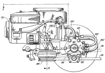
In order for the Dlower de~ S8 to ~e driven ~y a ~lngle
V-belt 74 connected with ~he e~ine crankshaf~ 76, c21~aranc~3
~ean~: 80 ~ust }~ pro~id~d for allowillg the V-belt 74 ~o pas~
~ro~ ~he engin6~ crank~h~t 7~ and underneath the transa~cle
hou~ g ~ ~o the input shaft ~ of the ~w~r de~c S8 (~e~
~. 3). This c:learanae ~o mu~t ~ ~uf~i~len~ ts3 all~w ~}~e
mower dsc:k 58 to hav~ adequ~t~ vertical float ~ that tha
transaxle ~ou~ing 82 ~oe~ not ~ontac:l~ or opor~tio~lly
inlk~3r~ a W~th ~e ~ }~31t 74 d~ing t31e 1~ran~:fer o~ Eu3wer ~Erox~
~he ~ngina cra~shaft 7~ to ~he mower i~pu~ ha~t 86.
To acc:ompliæh thi~, a~ ~hown i~ ~G~ . 3 - 6 ~ ~e
er~gin~l~r~n~axl~ c~in~t~on ~0 o~ the pr~sen~; in~ntio~
35 asse~lea to~ether with t}le engine ~r~ 76 ~ing
verticE~l and positione~ clo~a to ~he axle ~:en~er li~le 92 ~o
that the pull~y 94 (FIGS~ 3 aAd 4~ on the en~in~ cran~c~hz~ 76
i~ as ~210~:e to ~he tran~axl~ hous~ing 82 a~ bl0. ~I!hi8
~rr~r~ge~n1; m~nimize& po~ible in~rf~ena~ we~n l~lle ~Qlt
.,...~
13208~
~4 and the lower portion 96 o~ th~ tr~n~axle hou~in~ 82 a~ the
~ower ~ f loats over lme~v~2 terra~n ..
To provide ~ low ~ehi~le center o~ y ~h~ till
~aint~inlng ;~daquate c: learanc~ betw~n ~e pulley 94 and t:he
5 ground ~ ee FI~ ~), the engin~ 70 is~ co3~n~G1;ed t:o ~e
transaxl~ ~ z~ los~ to the ~ound 98 ac pr~a~i~;2~1..
In or~ler ~o pxovide adegua~e clear;ar~ae or the ~ elt 74
undex tl~e tr;~n axle housing ~ ren~ial un~t 100 is
po i~ion~d lnsi~e ar~d to one ~;id~a of ~ the ~r~nsaxle h~U~3~ ng 82
10 at a location pre~erably pxoxi~ate ~he riç~h~ ront whe~
t~ ~ow~r vehicle 50. In vehi~:le~ ~uipped w~h hya~oetatic
trans~i~ion~ ~see l?I~A S) ~ the h~d~o~o~o~ 104 ~ 0
prefera1~ly operatively pc~ ione~ ~n~:~de th~ 'cran~axle Iho~in~
~2 ~o on~ le ~n~l ~t a location proxi~ate the~ le~ ~ron~
15 wheel of the v~his 1~3o A sp~e~ re~uc:Sion gear 10~ i~
op~rat~vely pos~ tioned in~ide She t~n~:axle hou~ing 82
proxi~a~e the hydro~otor 104. The ~p~c~ic loe~ons o~ ~he
dif~er~nti~l ~00, the l~y~ro~otor 104 ~nd ~ s;pe~ edu~tion
gear 10~ ~an ~e varied within 'che ~ra3~axle ho~ ng
~o aa~ordin~ to ~pecific resluiremen~s~ it ~ein~ under6to~d that
oth~3~ arrange~nen~ o~ ~he variou~; sub-co~pc~nent part~ ~an be
pl~e~ ~n ot~er pos~tio~s than ~c~e illuætratoa an~ ~till ~e
within the ~cope of th~ prc~n~ in~verlt:~on.
In partiaular, on~ c:ritiaal a~peo~ o~ ~he pre~an~
25 inv~n~i~n 1~; ~he amoun~ o~ c:learanae ~equir~d ~y ~he ~ 74
wh~ch corm~cts the ~n~ e aran~c~;haft 76 ~i~ ~he l~pu~ m~ns
c~n ~h~ mow~r de ;:k SZ ~ In FIGS ~ 1 ~nd 3 I the ~o~r d~ k 58 is
~hown ~pera~ing on a level ~ aae~ me Y~Blt 74 ~no~ d
~etwe~n th~ ~n~ine ~ran~sha~ 76 and ~he ~os7er dea~c lnpu~
~o shaft 86 (~ee FIG. 3) 1~ ~:hown ~n ~t~ nor~al leve~ oper~ting
po~:ition~ However, wh~n the ~owe~ aeck 58 i~ cau~ed to ~o~e
ei'cher alwv~ or ~low the le~l ~sitiGn ~hown, ~uc~ ~ ~h~n
6~nc:0un~ring r~u~ll or uneven t~rrain, '~ mo~r dl~c:X 58 and
the belt 74 conne~a t~exe~o deflec~ her up~ardly or
3S downwardly from ~he lev~l po~tic~n of th~ ~n~ne pull~y ~4.
Sin~ o~ anu~a~turer~ r~ao~men~ onïy ~ 5 ~elt
misalignmer~t angle ~rom th~ leva~l pc~ ion, i. e, a~ tho bel~
exit the pulley~ ~he ~xe~t~r ~he ~ tia~ tan~ w~n
the pulley g4 aarri~d ~y ~h~ engi~e ~ar;~h~f~ 7~ and th~
.
.~
132~ 2
i~plem~nt input ~haft 86, the greilter th~ belt de~le~ion.
Thu~ he~e iG a re~ui~ment 'cAat th~re b62 ad~cauate a~ea~anae
80 ~a~ween th~ ~-b~lt 74 ~nd the lower por~ion 96 o~ ~h~
transaxl~ h~u~ing 82 to pr~v~nt th~ tr~n~axle h~ue:ln~ 82 ~rom
5 interer~ng wit2~ ~ b~lt operation.. This clear~na~ 80 i~:
o~ain~d by the arrang~en~ of t:~e varlou~; ~ub-compor;an~
within ~he tranl2axl~ hou~ing ~2 2~nd th~ tran~xle
con~suration wh~h a~sco~ ate~ the V~ de~le¢~onD
Anot~er con~ ration ~in the locatiorl v~ th~ ~riou6 ~3ub-
10 componen'c~ in the tr~n~a~cle hou~:ing 82 1~ tha ~Eluld f~s~w ~romthe ~n~in~ ~3~np llo ~e~ FIG;~. 5 ana S~ to t~e hydropu~np 112,
~he hy~lromo~or 104 ~nd baak ~o the hydropump 112. I.eakage~
from ~hi~ fluid flow system ~s. preerably utili~ t~a
lubricate the ~peed redu~~tion gear 108 ahd/or the d~f~erential
15 100 ~ Ag~er lubri~:a~on o~E ~he spee~ ~e~uation ge~r uni~ ~Os
and/csr ~he diffe~n~i~l unil: 100 " t~e flui~ ~æ r~urne~ to th~
en~ln~ ;eluid ~ump 110~
In ord~ to pro~ide ~7r ~ akx:~e~ the ~ollowi~g
component parts combination wa~ d~t~in~3d ~ ~ing one o~ a
20 plurali~y o~ possible combin~ation~ whiLah ~ight ~e
~ati~faa~ory. P.~ ~hown in ~he prefer;red e~odiD~n~ FIG~ 1 and
3 - ~, the ~ref~red ~ngine tranæaxle Gombi3l~ion ~0 inc:lude~
a ~ubular l~ransaxl~ hou~:in~ ~2 op~ively conn~ac:t~ to the
~ngine 70. ~h~ an~xle hou~ q 8a pr~fera~ly inaluae~ at
2~ lea~ a po~l:ion ~3 which pa:~tiall~ enc:a~:els 1;h~ e~inq~ 70 ~see
~IG. 4)., A~ ~hc~wn in ~IG. 5, ~he hydx~omotor 104 ~g po~ ioned
w~thill ~e t~ansaxle l~ousing 82 along wi~A the ~p~ed redllc~ion
~mit 108, the di~ferl3ntial unit 10~ ~nd th~la axl~ 10~ llts~
The hyarauli~ mot:or ~04 ~nolu~e~ a hollow ~xle ¢axri~er
~0 114 which i~; rota~a~ly suE~po~k~d ~ lts en~: by ~all ~ar~ngs
118 and needle beari~gg 12~. An ec:~:entria c~ix¢ular sl~av~ 12?
i8 *ox~ned at one en~ of the carri~ 114. P.L di~X~ ped
c:ylinder l~lo~ 122 ie2 ~ ly ~ ge~ with ~;pline~ ~orlAe~ in
t:he oute~ periphery o~ the carrier 1140 A plural~y o~
35 p~;ton~ 4 ~re equ~angularly proYid~ c:on~aal &~ a~
the c:yl~nt~er ~ A t~u~t plate lZ6 ~s ~r~vided ~Eor
reaeiving thru~ fro~ the pi~;ton~: 124 which A:~e rota~ably
~:upported wi~in th~ ~xia~ hou~s~ng 82, e~o ~hat the th~u~
plate 12~ ~ay x~ate ~n a ~orward d~rec:tion or ~ rever~
~32~8~2
direation. Th~3 ~ylinder hlock 122 ~ u:3ed ~ a bxa~
~here:Eore, a l~axld l~r~ke 1~ pro~i~e~ a~roun~ ~h~ aylin~er
blo~k 122 to ~ re a~ the bra~c~ m~ch~ni~
In or~er ~o supply power ~or operating th~ hydr~ulia
motor 104, a variable hydraulic pump 11~ ~c operatively
positione~ on t:h~ eng~ne 70 ~n~ riv~n ~y a 2am gh~t
~chani~ 130 (8ee ~IG~ 6~ which i oE~atiYely po2;~t~o~ed
in3ide ~he engine and operatively cos~nec~Q~ ~ith t:he
~k h ft 76
craI ~ a
~ particular arrangement i importan~ to ~:he overall
~uoqes~: of the aom~inat~cn. Spec:i~iq~ b~ po~ioning t~e
h~drop~mp 112 on the exterior of th~ eng~ne 70 ~nd by driving
it by ~ cam sh~ ge~ ~y~ po~itlone~ inside ~h~ engin~,
the engin2 c~uld ~ c~nne~t~d ~o the tr~n~axle 72 at 2~
po~ît~on relatively alo~r to the yroun~ t;h~n k~f~a. qihis
relatively lower pos~tioning pro~ es ~or a veh~ale wit~ ~
lowe~ centex of g~rity, the2~eby i~proving st~bili~y ~nd al~o
~edu~ing the le~h o~ the c~raxilc~ha~t 7~ ~hiçh ext~ om
~he b~ engin~ 70~
~hrough reduain~ the ho~i~ontal di~nc~ en the
engin~ crankshaft 76 and the tran~axl~ h~ 82, th~
vex~iaal dis~anae ~hrough whic~h t:;~e b~lt 74 swing~ ~neath the
low~r pc~ on g~ of ~;he tr~nsaxl~3 ~ou~ 82 w;~s ~edu~:~dlr
thereby ~ncr~a~ing the distance the ~xont mounte~ i~ple~enlt
a~uld ~o~e abc~re ~ :tevel po~$t~on rel~ltiv2 ts~ en~ina
pulley ~4 without h~vin~ ~he 1QW~ portion o~ r~n~axle
ho~ing 82 inter~r~ wit;h or c:ont~at the ~elt 74,.
A~ æhown in the plan ~ ew of FIG O ~, th~ hydropu~p 11~ iB
pxefe~a~ly ope~tively qonnecte~ to the l~t lowex :~de
por~ion of l:h6a ~ngin~ 70 o~ ~ne pre~re~ uniti~d ~ ine-
~ran~axle combina~lon g5. A~ ~hown in FIG~ wo ~ d
l~ne~ ~ ~0, 16~ ~r~ utiliz~l in ~luid c~om~u~C~2~ion bet~reen ~h~
hydropump 112 and the hydro~otor ~04, one li~e ~or flow in
~ach dire~:~ioh thea:eb~t~en, d~ n~ing upon ~he~her ~h~
vehic~le ~s operating ~n the re~er~e or th~ ~ rc31 ~rection.
Further ~e~ails: of t~e unitiz~ eng~ n~ onfi~ura~ion
rela~ed ~o t;he ~re~ent invention ~an ~e ~ouna in U ~ S ., Paten'c
5,0~7,~33, ~igl~ed ~o the ~igne~ of the pr&~nt invention
13208~2
A~ o~m ~in F~ , a mechani~3m ~or ~r~ns~errln~ p~w~r
dirQctly ~rom the engin~ aranlcsha~ 76 to the input 23ha~t ~13
o~ ~he hydropump 1~ trated. q~h~ hydropu14p 1~2 i~
d~x~tly connecte~ to the ~3ngine 70 ~ouyh t:he a~Q ~h~t 130
whiah ha~; ~ c~m gear 170 opera~ ly connected th~xeto. ~rhe
~am ~:haft ~30 is po itioned intermed~ate an~ para~lal to th~
engine ~r~ks~a~ 7~ and th~ hydrof?~t~tic pump inpu~ ~h~f~
113. The a~ gear ~70 ~n~lude~ ~w~ ~eparat~ portions 172, 174
each having t:~eth 176, 178. one o~ the cam gear po~tiong 172
~0 inter~eB~es ~ith ma~h~ng t:ee~h 1~0 on the eng~ne c~a~c~haft
76 ~n~ o~her ca~ gear po~on 174 int~r~ae~e$ b-ith ~natin~
te~th ~82 on a gear 184 G~ d ~y t~e hyd~o~t~t~c pump input
sha~t 113. Th~ shaf~ olE t21~ aam gear ~nech~ni~m 130 in~lude
She cam 131 and ~he ca~ srea~c ~70, bot2~ of ~hiah ~r~ po~it~onea
in~;id~ ~he engine~
rhe drivins~ or powering of 1:he hy~rost~tlc pu~p 112 by
tbe ~ gea~ m~acshani~n 13~, in~3ide t:he ençlin~ 73, pro~ideæ ~or
in~r~asin~ the fli~tance ~tween th~ enél of eng~ne ~rari~c.ha~t
7~ ~e hydro~ati~ pt~mp 112 and tho en~ine ar~nkoh~t 7~ are
2 o othex~i~3e ~onventionally c~ ru~tea .
Thîs partiaulax ~ructure for pow~ering th~ hy~rostat~ ~
pump ~2 whic:h provid~æ ~or ~c~e engine ~o ~ po~ Pne~ clo~:er
r~lati~r~ t~ t~e ground al~o redu~ Y~ c~nt~r
~ravi~y and theroby lncrea~eæ the v~ le'~ ~tab~lity. .
T~* ~peed r~duction uni~ 108 i~ a pl~n~tary ql~aar
red~action type ~ is well known in t~e axt. Pl~nekar5~ piniorls
13~ ar~ ~eshed with an~ ~ri~ n ~ an out~r p~arîphery o thQ
c:i~rcular ~;leeve p~cion 127 o~ the carrier 114 1:hrou~h ~11
~aringç~ and ~ inner ~e~th o~ a r~n~ ge~ 4 are ~lx~d
3 0 to th~ axle ~c~u~ 2 and are Dle~hea wi lth the oute~ ~Qth 13 3
o~ the p~ane~y pinions 132. S~ e~ are ~or~ n t~ r
p~ipllery o~ She bos~ por~io~ oi~ the pl~ne~ry pln~on~ 132.
A~ ~ho~n, it i~ pre~err~d th~t the planetary ~i~ions 13a ha~e
one 1~8 ~ooth th~n ~he ring~ g~ar 134.
~he di~f~rent~ial uni~ 100 in~zlu~e~ a ~lsul~r s~ erentia
~ear box 136 whic~ is i~el~ rot~ bly ~uppor~:~d ~ e
~le hous~ ng B2 by b~ earin~s ~3~ 0 Op~rati~ly aonnec'c~d
~co th~ di~erential ge~r ~x 13~ n endl ~h~é 140 ~uppc-r~
me~r. In ~he preferrecl e3~0d~hent, thi~ ~r ~40
11
~320~52
forxR~d af~ an in~e~ral portlo~ o~ tha gear box 1~6. A pair o~
æmall l:Nav~l gear~ 142 ~re rotat~bly pivote~l in tl~e inn~r
peripher~l por~ion o~ the dl~erential geilr box 136" A pair
oP ~a~ bevel g~r~3 144 en~e the pair o~ ll bevel ~ar~;
5 142 ~nd ~re rot~tably ~pported b~ ~e inner per~p~e:rie~ o~
th~ a~f~rential gear box 13~ and the en~ ~ha~t 8upport mem~er
140. 5pl~ne~3 146 ar~ ~ormed in ~n end portion of 1:hç~ ~nd
s~f~ ~support ~ r 140~ ~me ~3plinQ~ 135 c~ planet~ry
pinion 132 ar~ opexat~vely co~nec~e~ ~o ~h~ spl~ne 146 o~ t:he
0 s~ha~t ~r t~e. axial hollo~r ~pllne lS0 .
TAe ax~e ~nit al:3o inalu~e~ a l~ng a~la Dle~bex ~5~ and
8hort axle ~emb~3r 1S4. ~he l~ng axl~ ~ember 152 ~
op~rat~rely ~onnect~3d a~ one end to an inner periE~hery of one
o~ ~he large ~evel ge~r~; 144 ~nd pro~f3a~ at ~he other end
~rom one side of th~ ax~ hou~:ing 8~ pas~ing throuslh t~
holls~w ap~rt~lre~ o~ the carriex 114 2md . he pline ~50~ The
o~her ~nd of ~h~ lon~ z~x~a 1~2 is rota~a~ly uppor~d in the
~xle hou~ing 82 by ~he needle ~earings 120 and the ball
]bearin~3 15~, The short axle 154 is ¢onnç~c:t~d ~o one ~nd o~
~0 the inner periphe;rsr o~ ~he o~er l;~ge bevel g~ar 194 tl~r~ugh
s~ n~ ; rota~a~ly ~;upport~d at the othl3r en~l on ~:he ot~r
siCle o~ ~he axle hou~ g 82 1~ ball beari3lg~ 14~ and pro~al~
to ~he out~;~de. The drive ~he~ls 64 ~re fixcad to 1:~e
projecting porl~ion~ o~ ~he lc~ng and ~ho~c~ axle~ 1~2 ~nd 154
2 5 re~pec~ti~ely .
In the preferred ~m~c!li~enl~ to provide: a~equaS~ belt
c:lear~rlc~ ~0 und~r the transaxl~ hou ing ~2, ~ ai~ r 0~
the ~rane~a~le hou~inS~ 82 is re~u~d a~3 much a: po~:sil~le . The
~e:du~ed c~n~;ral port~ion doe~2 no~ int~rfe~e Wi~ he ~evolution
30 of the ~nd ps~r~ion on ~e planet ary pinio~ 132 o~ ~h~ ~pline
~ointE; 135 ~:inc~ th~y ar~ lwated to one end ~ the ~ransaxle
hou~irg 82 . A~ th~ ti~e, a~ sho~rn in P~S . 3 and 4, the
axle housing center line x--x ~; loca~ea ~o~e a horizontal
llne ~ough the ~en~erline oi~ ;IX12 y--y. ~hu~, ~;hQ al~arance
35 or spa~e 80 1~: formed w~ h p~ovl~le~ adequate l:learanoQ ~or
the V belt 74 which ~onrle¢~ the engin~a 70 with th~ ~o~king
imple~en1: ~8 to oper~e and ~till pro~idæ ade~aua~e ~aple~nent
~ertical ~loat.
12
A
1~2~2
;~ring th~ opex~on of the ~y~r~ulic motc)r 104, the
wor~cing ~lui~ w}~ h l~ak; ~herefro~, ~lows ~rough the
tran~axl~ houcing 82 ~n~o ~h~ Ghamber c:ontalnlng the
di~erent~al ~nit 10~, and i~ returned ~ to th~ vari~bl~
S hydrau~ia pump 11~ through a return pipe lgo. In th~3
pref~rr~d embodi~ent" the f~id is; r~turned to ~he engin~ a~mp
110 through in~ern~ a~s ~not shown~.. The fl~w ~2~t~ o~ th2
leakage of th~ hy~aulic: motor 104 to ~h~ dif~eren1;ial unit
ïOO i:~ inc:rea~ed ~lue to the fluid diameter of ~e p~ag~,
lo i ~ e. the transa~le ~ou~:ing ~:ro~ ec:t~on~ ~rc~l~ t:hat point over
to t~ di~ere~tial 100 be~ng re~luoed. ~rh~a working ~luid 1
cooled by c:ool~r2g fin~ ~no~ ~hown) formed aro~ ~h~ aen~r~l
port~on ~x the ~luicl p~ 3e8 Shrough ~he deoreas3ed di~etlar
pa~. ~ge.
In op~xa~i~n, wor~cing flu~d i~ uppl~ed to th~ hya~aulic~
motor 104 by the va~i~b~ hydraul~c: pu~p 1~2 which is~ dri~en
the er~gin~ cr~ haft 7~. Ro1~ion o~ the c:ylind~r bloc~c
122 causes 1the cirau~ar sleeve ~27 o~ ~he c~arri~r :L~4 to
ao~c:entric~ly rotate a~ ~e ~ame rs~ational ~:pe~ad~
Tl~er~fore, the plan~ary p~ni~n~: 132 ar~ meched ar~d revolve
- with the rin~ gear 134 so ~ha~ th~ planet~y pinion~ 132 are
rota~e~ a~ut ~heir o~m a~e~ in the rever~:e ~lireu~tlon to the
r~volution pr~duced by ~e hydro~o~or 3lO4n ~rhe rot~tlonal
motion Df~ 'ch~ planetary pin~ons 132 i8 t~ans~ te~i ~o ~
~plin~ 150 which in t~arn dr~ves the ai~ ~er~an~iAl gear box 13~,
which in turn ari~res the ~;mal~ be~el gear~ 142 to d~e th~
large ~el gears ~4A and t~e sha~t 15~ whlch i8 æpl~rled to
~he ge~r~ 144 a ~e crank ~ha~t 76 c:au:s~s ~ r~n~i al
~ear box ~36 ~o rotate and ~ &aus~3 th~ lor~s~ and short
axle~ 15~ an~l 154 ~o rotata th~ough th~ en~ag6~ 6~all and
large k~e~ ears 14~, 14~, thu~, rotatin~ ~ot:h the drivi~g
wheel~; 64. With the in~lusion o~ t~e ~lif~eren~al unl~ 100,
when ~he ~rehiel~ is ad~ranced ~ htly, t~e dri~in~ wheel~ 64
are rotated th~ ame rc~tational p~eds, but when t~e ~rehi~le
i~ a~an;:ed allong ~ c~rved path, ~e ~ri~ wh~3el os~
ou~Eide o~ e s~urve pat21 i~; ro~ d at a hiçlh~r ~;peed tha2
the other d:ri~ç~ whee~ on ~he in~3id~ o~ the aurve p~th.
on ~h~ o~her han<l, th~ cranlc~h~t ~ the eng$n~ ?0 1
opera~i~ely po~ ioned to drive the isA~ t ~nput ~ ft
13
~32~8~2
through the belt p~lley. ~rhe V-belt 74 ~nd the bel~ pull~y 86
are op~3ratively ~o~r~ected tc~ work~ng i~ple~en~ tb~ou~ the
rance or ~pac:e BO ~xea~d b~r tha ~ele~;l~ pO3~ tioning 0:~
~he tran~xle c:ompone~ h~&, ~ven lf~ th~ ~Eron~ ~oun~e~
5 implaJaenl: i~; move~ ~;ic~lly ~n r~p~nE:e to 1~ Cl~;
txa~r3i;~ng une~n ground whic:h may hav~ d ~ h, ~h~
~pace and th~ tranE:axl~ ~hrou~ which the ~ pa~6~se: i~ o
a u~ ien~ width And heigh~ 80 tha~ the ~ c wll~ nol~
~nt~rfere with ~he botto~ ~rfa~:~ o~ ~he t~ar~saxl~a h~Uglin-;Jr
~ith ~is~ ~onstruotion, there i: Jlo n~ or the
conv~ntional int~rmedia~e shaPt ~nd lthe u~e o t:wo ~l~s~, one
~ro~ the ex~gin~ to th~ int;ermediate sha~t and the other f~
inter~ned~a~e shaf~ to th~ work~n~ i~pl~nt:~ ~e re~:ult
is ~ignif~can~ly ~re~ter vertic~ loAt, dec~aeed ~ erl~l
15 manu~acture and ~Rm~ly ao~:t arld a lowex Yehi~le c~ent~ o~
gravity while mai~t~ining adegu~t~ g~ound cl~ar2~nae for the
engine output ~2~aft 7 6 .
Wh~lq ~he ~ethod a21~ operat;ion herein aeScri~ed
cotls~i~ute pre~err~d e~bod~nen~s o~ the in~en~on, ~t i~ to
20 unde~stood that th~ i~vention i~; no~ li~l~ed to th~ p~e~
method an~ operation, ~nd the change6 may b~ ~de t:l~erein
with~t depar~ing ~rom the ~ $ ~h~ inYent::~orl ~bic~
~e$ir~ed ~n the appen~led clai~s~.
~4