Language selection

Search

Patent 1321058 Summary

Third-party information liability

Some of the information on this Web page has been provided by external sources. The Government of Canada is not responsible for the accuracy, reliability or currency of the information supplied by external sources. Users wishing to rely upon this information should consult directly with the source of the information. Content provided by external sources is not subject to official languages, privacy and accessibility requirements.

Claims and Abstract availability

Any discrepancies in the text and image of the Claims and Abstract are due to differing posting times. Text of the Claims and Abstract are posted:

  • At the time the application is open to public inspection;
  • At the time of issue of the patent (grant).
(12) Patent: (11) CA 1321058
(21) Application Number: 573389
(54) English Title: FITMENT INSERTER MACHINE
(54) French Title: MACHINE D'INSERTION D'ACCESSOIRES
Status: Deemed expired
Bibliographic Data
(52) Canadian Patent Classification (CPC):
  • 26/88
(51) International Patent Classification (IPC):
  • B65B 7/28 (2006.01)
  • B29C 65/56 (2006.01)
  • B29C 65/78 (2006.01)
(72) Inventors :
  • ST. CLAIR, DAVID L. (United States of America)
(73) Owners :
  • OWENS-ILLINOIS PLASTIC PRODUCTS INC. (United States of America)
(71) Applicants :
(74) Agent: GOWLING WLG (CANADA) LLP
(74) Associate agent:
(45) Issued: 1993-08-10
(22) Filed Date: 1988-07-29
Availability of licence: N/A
(25) Language of filing: English

Patent Cooperation Treaty (PCT): No

(30) Application Priority Data:
Application No. Country/Territory Date
092,095 United States of America 1987-09-02

Abstracts

English Abstract


ABSTRACT OF THE DISCLOSURE
A fitment Inserter machine, such as a machine for inserting a spout into
the top opening of a blow molded container is disclosed. A conveyor continually
moves containers through the machine. A transfer arm and rotary placer
removes the lowermost spout from a vertical dispenser and places the spout on a
moving container. Jaws grasp the container finish while it is still moving and
hold the finish while a pressing head mounted on a flying table moves
downwardly to press the spout into correct alignment with the container.


Claims

Note: Claims are shown in the official language in which they were submitted.


The embodiments of the invention in which an
exclusive property or privilege is claimed are defined
as follows:
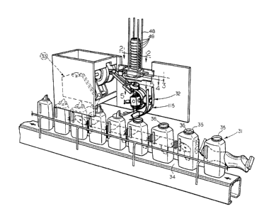
1. A fitment inserter machine for inserting a
fitment into a container having an opening for
receiving such fitment, the machine comprising,
conveyor means for serially moving a plurality of
containers,
placer means for placing a fitment at a
container opening while such container is moving,
and pressing means for pressing such fitment
into such container opening while such container is
moving,
said pressing means including mating jaws for
grasping and holding such container adjacent such
container opening during pressing of such fitment.
2. A fitment inserter machine, according to
claim 1, wherein said placer means includes a dispenser
for holding a vertical stack of such fitments,
alignment means for rotating the lowermost fitment to a
correct alignment, roller means for moving the inserts
downwardly, a transfer arm assembly for removing the
lowermost one of the fitments from the vertical stack,
and a rotatable placer means for receiving the
lowermost fitment and placing such fitment in a correct
alignment into the opening of a moving container.
3. A fitment inserter machine, according to
claim 2, wherein said rotatable placer includes a bevel
gear, a plurality of planetary spindle assemblies
having planetary gears meshing with said bevel gear,
each of said planetary spindle assemblies including an
outer end for receiving a lowermost fitment, such
spindle assembly rotating relative to said bevel gear
for placing such fitment into such container opening.
4. A fitment inserter machine, according to


claim 3, including finger means on said outer end of
said spindle assembly for receiving and maintaining
such fitment in a correctly aligned position.
5. A fitment inserter machine, according to
claim 3, including delay means for adjusting the
relative speed of rotation of said spindle assembly
relative to said bevel gear prior to placement of such
fitment on such container.
6. A fitment insert machine, according to claim
5, including a driven shaft, wherein said delay means
includes an eccentric mounted on said driven shaft, a
follower arm assembly extending outwardly from said
eccentric, said arm being operatively connected to said
bevel gear, whereby rotation of said eccentric rotates
said bevel gear to effectively delay movement of said
spindle assembly at the time of placement of a fitment
on a container.
7. A fitment inserter machine, according to
claim 3, including a curvilinear guide chute positioned
adjacent said bevel gear for receiving such fitment
during movement from such vertical stack to positioning
on such container.
8. A fitment inserter machine, according to
claim 2, wherein said transfer arm assembly includes a
transfer head, a parallelogram linkage mounting said
head and cam means operatively connected to said
parallelogram linkage whereby said head receives such
lowermost fitment and delivers it to said rotatable
placer means and returns to the next lowermost fitment
in the vertical stack.
9. A fitment inserter machine, according to
claim 2, wherein said alignment means includes a
friction pad for engagement with the fitments in the
vertical stack and cylinder means operatively connected


11
to said friction pad for moving said friction pad into
and out of engagement with the fitments and for
reciprocating said friction pad for rotating and
aligning the lowermost fitment.
10. A fitment inserter machine, according to
claim 9, including sensor means operatively connected
to said cylinder means for sensing the alignment of the
lowermost fitment and for energizing said cylinder
means to place the lowermost fitment into the correct
alignment.
11. A fitment inserter machine, according to
claim 1, including a flying table mounted for movement
adjacent said conveyor means, and wherein said presser
means includes a presser head mounted on said table,
said presser head moving at the speed of the bottles
during pressing.
12. A fitment inserter machine, according to
claim 11, including first cam means operatively
connected to said table for reciprocating said table
and second cam means for closing and opening said jaws
and for vertically moving said presser head.
13. A fitment inserter machine for inserting a
fitment into a container having an opening for
receiving such fitment, the machine comprising,
conveyor means for serially moving a plurality of
containers;
placer means for placing a fitment at a
container opening while such container is moving; and,
pressing means for pressing such fitment into
such container while such container is moving, said
pressing means including a flying platform mounted for
movement adjacent the moving containers, a vertically
movable head on said platform for pressing the fitment
into the container opening, jaw means carried by said


12

platform for grasping and holding the container portion
adjacent said opening and means for closing said jaw
means around said container portion and holding the jaw
means closed while the moveable head is lowered to
press said fitment into said container opening.
14. A fitment inserter machine for inserting a
fitment into a container having an opening for
receiving such fitment, the machine comprising,
conveyor means for serially moving a plurality of
containers,
placer means for placing a fitment at a
container opening while such container is moving, said
placer means including a dispenser for holding a
vertical stack of such fitments, alignment means for
rotating about the vertical axis defined by said stack
the lowermost fitment in said stack to a correct
alignment, roller means for moving the fitments
downwardly, a transfer arm assembly for removing the
lowermost one of the fitments from the vertical stack,
and a rotatable placer means for receiving the
lowermost fitment and placing such fitment in a correct
alignment into the opening of a moving container.
15. A fitment inserter machine for inserting a
fitment into a container having an opening for
receiving such fitment, the machine comprising,
conveyor means for serially moving a plurality of
containers,
placer means for placing a fitment at a
container opening while such container is moving;
and pressing means for pressing such fitment
into such container opening while such container is
moving,
said pressing means including mating jaws for
grasping and holding such container adjacent such


13

container opening during pressing of such fitment;
said placer means including a dispenser for
holding a vertical stack of such fitments, alignment
means for rotating the lowermost fitment to a correct
alignment, roller means for moving the fitments
downwardly, a transfer arm assembly for removing the
lowermost one of the fitments from the vertical stack,
and a rotatable placer means for receiving the
lowermost fitment and placing such fitment in a correct
alignment into the opening of a moving container, said
rotatable placer including a bevel gear, a plurality of
planetary spindle assemblies having planetary gears
meshing with said bevel gear, each of said planetary
spindle assemblies including an outer end for receiving
a lowermost fitment, such spindle assembly rotating
relative to said bevel gear for placing such fitment
into such container opening, delay means for adjusting
the relative speed of rotation of said spindle assembly
relative to said bevel gear prior to placement of such
fitment on such container, said delay means including
an eccentric mounted on said driven shaft, a follower
arm assembly extending outwardly from said eccentric,
said arm being operatively connected to said bevel
gear, whereby rotation of said eccentric rotates said
bevel gear to effectively delay movement of said
spindle assembly at the time of placement of a fitment
on a container.
16. A fitment inserter machine for inserting a
fitment into a container having an opening for
receiving such fitment, the machine comprising,
conveyor means for serially moving a plurality of
containers;
placer means for placing a fitment at a
container opening while such container is moving;


14

and pressing means for pressing such fitment
into such container opening while such container is
moving;
said pressing means including mating jaws for
grasping and holding such container adjacent such
container opening during pressing of such fitment, said
placer means including a dispenser for holding a
vertical stack of such fitments, alignment means for
rotating the lowermost fitment to a correct alignment,
roller means for moving the fitments downwardly, a
transfer arm assembly for removing the lowermost one of
the fitments from the vertical stack, and a rotatable
placer means for receiving the lowermost fitment and
placing such fitment in a correct alignment into the
opening of a moving container, said alignment means
including a friction pad for engagement with the
fitments in the vertical stack and cylinder means
operatively connected to said friction pad for moving
said friction pad into and out of engagement with the
fitments and for reciprocating said friction pad for
rotating and aligning the lowermost fitment.
17. A fitment inserter machine according to claim
16, including sensor means operatively connected to
said cylinder means for sensing the alignment of the
lowermost fitment and for energizing said cylinder
means to place the lowermost fitment into the correct
alignment.

Description

Note: Descriptions are shown in the official language in which they were submitted.


13210a8


FITMENT INSERTER MACHIN~
BACKGROUND OF THE INVENTION
The present invention is directed to a fitment inserter machine and
particularly to a machine for inserting a spout into the top opening of a blow-
molded plastic container. Blow-molded containers having either Jntegral or
5 separable spouts at their upper end are known in the art. When the spout is
separable, it must be aligned and pressed into place accurately in the top of the
container.
In prior machines, failures sometimes occurred because in a high
production operation the container finish must be supported during the pressing
10 operation or deformation occurs. Also, prior art machines were often slow since
the container conveyor had to be stopped during the alignment of the spout in
the container opening and also during the pressing operation.

SUMMARY OF THE INVENTION
The fitment in~erter machine, according to the present invention,
maintains orienhtion Or the insert or spout ~ ith the contsiner and also matchesthe~ speed of the container while syncronizing the spout position with the
contalner. During the pressing operation, iaws support the finish of the
container during pressing to prevent pressing pressure from nexing or collapsing20 the container finish. A stop/start operation is not required and the pressingoperation occurs while maintaining the speed of the containers as they move
through the fitment inserter machine.
The fitment inserter machine include~ conveyor means for serially and
continuously moving a plurality o~ containers through the mnchine. Placer
25 means remove a fitment or spout from a vertical stack after alignment and
places the spout at the container opening, while the container continues to move.

-2- 13210~8
A head presses the spout into the container while mating jaws grflsp ~nd hold the
container finish during the pressing of the spout into posltion in the containeropening.

5 RIEF DESCRIPTION OF THE DRAWINGS
Fig~ 1 is a perspective view of a fitment inserter machine, according to the
present imrention;
Fig. 2 is a view of a fitment, in this case a plastic insert spout for ~ blow-
molded bottle, taken along the line 2-2 of Fig. 1 and shown on an enlsrged sca1e;
Fig. 3 is a view simllar to Fig. 2 taken along the line 3-3 of Fig. I;
Fig. 4 is a view similar to Fig. 2 taken along the line 4-4 of Fig. l;
Fig. 5 is a view similar to Fig. 2 taken along the line 5-5 of Fig.l;
Fig. 6 is a cross-sectional view taken along the line 6-6 of Fig. 2;
Fig. 7 is an elevational view of the fitment shown in Fig. 2;
Fig. 8 is front elevational view of the fitment inserter machine, according
to the present invention;
Fig. 9 is an end view of the fitment inserter machlne shown in Fig. 8 and
taken on an enlarged scale;
Fig. 10 is an exploded view showing several of the drive components of the
fitment inserter machine, with some o~ the mechanisms shown out oi' position forclarity;
Fig. Il is a fragmentary, elevational view, with parts removed for clarity,
showing the placer means of the fitment inserter ma2hine;
Fig. 12 is a top view taken along the line 12-12 of Fig. 8 end shown on an
enlarged scale;
Fig. 13 is a top view, shown partially in cross section and showing drive
rollers ror moving spouts downwardly through the vertical dispenser;
Fig. 14 is a cross-sectional view taken through the llne 14-14 o~ Fig. 13;
~ Fig. 15 i9 a view similar to Fig. 13 and showing the bottom view;
Fig. 16 is a cross-sectional view taken along the line 16-16 o~ Fig. 13;
Fig. 17 is a schematic view showing the driving cylinders and the cylinder
valving o~ the alignment means;
Fig. 18 is a cross-sectional view, shown on an enlarged scale taken along
the line 1~-18 of Fig. 11;
Fig. 19 is a fragmentary, cross-sectional view taken along the line 19-19 of
Fig. 18;
Fig. 20 is a front elevational view, with parts removed ~or clarity, taken
generally along the line 20-20 of Fig. 18;

_3_ l32~0~8
Fig. 21 is a cross-sectional view, taken Rlong the line 21-21 of Fig. 20, and
shown on an enlsrged scale;
Fig. a2 is a fragmentary front elevatlonal view, shown on an enlarged scale
and showing the presslng means of the fitment inserter m~chine, accord3ng to
5 the present Invention;
Fig. 23 Is a cross-sectlonal view taken generfllly along the llne 23-23 of Fig
22 and showing the position of the pressing mechanism prior to pressing;
Fig. 24 is a view similar to Fig. 23 taken along the line 24-24 of Fig. 22 and
showing the pressing means after pressing;
Fig. 25 is a top elevational view, showing the pressing mesns; and
Fig. 26 is an exploded view showing various components of the pressing
means.

15 DESCRIPTION OF THE PREFERRED EMBODIMENTS
Referring to Fig. 1, a fitment inserter machine, sccording to the present
invention, is generally Indicated by the reference number 30. The machine 30
Includes conveyor means 31, placer means 32 and pressing means 33. The
conveyor means 31 includes a continuous belt conveyor 34 for transporting a
20 plurality of containers 35. In the present embodiment, the containers 35 are
blow-molded plastic containers having a threaded openlng 36 deflned in their
upper ends. Referring to Fig. 10, the fitment inserter machine 30 has many
components driven by a motor 38. One Or the components driven by the motor
38 is a rotating screw member 39 which is positloned adhcent the belt conveyor
25 34. The screw member 39 serves as a bottle separator for spacing the cont~iners
35 as they trarel toward the placer means 32. Referring to Figs. i and 10, a
secondary spacer mechanism is positioned downstream of the screw member 39.
Thls includes a contlnuous endless belt 40 having Rn upper night 41 and a lower
fllgbt 42. The endless belt 40 is also driven by the motor 38 and includes a
30 plurallty o~ spacer members 43 whlch extend horizontally outwardly throughoutthe upper night and are moved downwardly whlle on the lower flight 42 as
Indlcated by the reference number 43. When the spacer members 43 ~re in the
43 posltlon, they do not Interfer with the successiYe containers 35 moving alongthe belt conveyor 34. As shown in Flgs. 1 and 10, the spacer members 43 abut
35 the Q~olnlng contalners 35 to malntain the contalners 35 In thelr correct spaclng.
In the present embodiment, a driven star wheel 45, powered by the motor
38 Is posltloned adjacent the continuous belt 34. The star wheel 45 deflnes

13210~8
--4--
recesses 46 on its surface for receiving and ~ligning the upper ends of the
containers 35~ as best shown In Flg. 10.
Referring to Flg. 9, a handwheel 44 is connected to a threaded shaft 47
whlch Is operatlvely connected to an upper fr~me portion 53 of the machine.
The upper trame portion 53 mounts the plAcer means 32 and the pressing means
33. Rotation of the handwheel 44 vertically moves the upper frame portlon 53
adjustlng the spacing relative to the conveyor means 31. This adjustment is usedwhen containers of dlfferent slze are run on the machine 30.
Referring to Flg. 1, the fitment Inserter machine 30 includes a vertical
dispenser 48 for holding a vertical stack of fitments, for example the pouring
spout fitments 49, best shown in Fig. 7. Each spout 49 includes a rim 50 which is
pressed downwardly against the container 35 after the spout 49 is positioned in
the container openlng 36 as described subsequently.
Fig. 7 shows the spout 49 in its OrientRtiOn upon insertion into the
container opening 36. As the spouts 49 move downwardly in the vertical
dispenser 48, they are 1~0 reversed from the Fig. 7 position and have the upside
down orientation shown in Fig. 6. Generally, as the spouts 49 move downwardly
in the vertical dispenser 48, when viewing from the top9 they have the
appearance shown in Figs. 2-5. The spout 49 includes a pouring member 51 which
defines an elongated opening 52 therethrough.
Referring to Figs. 10, 13 and 14, roller means for moving the spouts 49
downwardly through the dispenser 48 is generally indicated by the reference
number 55. The roller means 55 is driven through a shaft S6 operatively
connected to the motor 38. A gear 57 is mounted on the shaft 56 and mates with
a gear 58 mounted on a stub shaft 59. Journals 60 and 61 are provided for the
shafts 56 and 59, respectively. A roller 62 is mounted on the shaft 56 and a
roller 63 is mounted on the sha~t 59. Ro~t~on of the driven shaft 56 rotstes therollers 62 and 63 to engage the rim 50 of the spouts 49 and urge the spouts 4g
dow,nwardly as indicated in Fig. 14.
Re~erring to Figs. 14, 15 and 17 an aligning means for rohting the
lowermost fitment or spout 49' to a correct alignment is generally indicated by
the reference number 67. Refçrring to Fig. 17, the alignment means 67 includes
an L-shaped bracket 68 which mounts a positioning cylinder 69 having Q rod 70.
The rod 70 is operatively connected to an alignment member 71 having a friction
pad 72 ror engagement with the spouts 49. The bracket 68 also mount~ t~ndem
cylinders 73 and 74 having a rod 75. The rod 75 is also connected to the
alignment member 71 and reCiprocQtes the alignment member 71 horizontally
along a tangent of one of the spouts 49. During acuQtion, the rod 70 of the

1321 058


cylinder 69 is extended to pivot the frictlon pad 72 of the allgnment member 71
Into engagement with the sldewall of the spout 49, as indicated in Fig. 15.
Optical sensors 76 and 77 sense the posItion of the lowermost spout 49. Based
upon the reading of the sensors 76 and 77 the t~ndem cylinders 73 and 74 are
5 extended or retr~cted to horlzontally reciprocate the alignment member 71 and
place the lowermost spout 49 in its correct alignment. Fig. 3 diagrammatically
illustrfltes how the fltment or spout 49 may be rotated through an arc of 20 byreciprocating the alignment member 71.
A transfer arm assembly is generally indicated in Figs. 8, 11, and 12 by the
reference number 80. The transfer arm 8û is driven by the motor 38 through a
shaft 81 which mounts a cam member 82. The cam member 82 defines a cam
recess 83 which receives a follower 84 mounted on one end of the transfer arm
assembly 80. The transfer arm assembly 80 includes opposed parallel main links
85 which pivot on a pivot pin 86. Lower links 87 are mounted adjacent the main
15 links 85 and form a parallelogram linkage with the main links 85. A transfer
head 88 having opposed trans~er supports 89 at its outermost end, is connected to
both the main links 85 and the lower linlcs 87. The transfer supports 89 receivethe lowermost spout 49 and transfer such spout to the placer means 32.
The placer means 32, referring to Figs. 8, 11, 18 and 19, includes a main or
20 bevel gear 93. A plurality of planetary spindle assemblies 94 having mating
gears 95 are mounted on the bevel gear 93. Each of the planetary spindle
assemblies 94 includes an outer end 96 which receives the lowermost spout 49 as
it is lowered downwardly by the transfer arm assembly 80. Pivotal fingers 97
and 98 are mounted ad~acent the outer end 96 of each planetary spindle assembly
25 94 for receiving and maintaining the lowermost spout 49 in the correctly aligned
position.
Delay means are provided in the fitment inserter machine 30, according to
the present Invention, for ad~ustlng the relative speed of rotation of the spindle
assemblles 94 wIth respect to the bevel gear 93. As best shown in Fig. 18, the
30 splndle assemblIes 94 are rotatably mounted on a hub 99 which is mounted on ashaft 101. The shaft 101 is driven by and operatlvely connected to the motor
38. For each rotation of the shaft 101 the spindle assemblies rotate four times.The bevel gear 93 is mounted on a sleeve 10a and is normally stationary with
respect to the mating gears 95 durlng their rotation. As a planetary spindle
35 assembly 94 moves from the up position where it receives the spouts to its lower
position where it deposits the individual spout 49 in the opening 36 of an
individual container 35, the spout is rotated to the orientation shown in Fig. 7.

1~2~ ~8
--6--
The delay or intermittent motion means slows the movement of an
Indlvidual spindle assembly 94 at the time of depositing its spout 49 at a
container opening 3fi. Because the contalners 35 are stIIl moving along the
conveyor 34 as the spouts 49 are placed in the container openings 36, the delay
5 ensures correct positioning when the spouts 49 are dropped.
The delay means includes an eccentric 104 mounted on the shaft 81. A
follower arm assembly 105 includes an end 106 adjacent the eccentric 104. A
swivel connection 107 is mounted on the other end of the follower arm assembly
105 and is pivotally connected to a drive member 108 which is mounted for
rotation by a bearing 109 on the shaft 101. As best shown in Fig. 18, the drive
member 108 is connected by a pin 110 to the bevel gear 93. A threaded
ad~ustment screw assembly 111 (see Figs. 20 and 21) mounts the pin 110 and
provides for manual adjustment of the bevel gear 93 relative to the planetary
spindle assemblies 94 and the matlng gears 9S. The delay means adjust the
lS relative speed Or rotation of the spindle assembly 94 relative to the bevel gear
93 immediately prior to the placement of the spout 49 on the container 35. The
eccentric 104 acting through the follower arm IOS rotates the drive member 108
which transfers its movement through the connecting pin 110 to the bevel gear
93 to supply the changing relationship between the bevel gear 93 and the mating
gesrs 9S to ensure the desired slowing or delay.
Rererring to Figs. 1, 8 and 11, a curvilinear guide chute assembly llS is
posltioned ad~acent the be~!el gear 93 for receiving and guiding the spouts 49 as
they are rohted downwardly from the vertical dispenser 48 to positioning on the
containers 35.
The length of the arm assembly 105 and the stroke of the eccentric 104 are
such that during the forward motion the spindle assembly 94 will stop rotation
long enough to place the spout 49 into the mouth of the container 35 and allow
the spindle assembly 94 to leave the spout 49. During the ~ck or return motion
the ~plndle assembly rotates 360 degrees.
The plvotal fingers 97 and 98 at the outer end 96 Or each spindle assembly
94 are spring loaded. The flnger 98 is relstlvely narrow and complementary with
the wldth Or the elongated openlng 52 in the spout 49. The other flnger 97 is
relatlvely wide and rounded and rIts the curve Or the spout 49. The fIngers 97
and 98 collapse to allow the narrow end Or the spout 49 over the end of the
spindle assembly 94. Because the sposlt 49, in the present embodiment,-is conical
shaped, it is wider at the end where the fingers 97 and g8 are located. The wide

7 ~21~8
.
finger 97 keeps the spout 49 in the proper location so that the narrow finger 98can find the elongated openlng 52 In the spout 49; flip out; and drive the entire
spout 49 around for placement in the container 35.
Referrlng to Figs. 2a-a6, the pressing means 33 includes a flying platform
or table 116 which is mounted for reciprocal movement by parallel bars 117. The
table 116 reciprOCAtes along the bars tl7 to enable a pressing head 118 to move
at the speed of the contfliners 35 during the pressing operation. A vertical
support post 119 extends upwardly from the table 116 and slideably mounts a
horizontal strut 120 which defines a track 121. The head 118 includes a shaft
123 which is mounted by a block 124 to the horizontal strut 120. A cross
member 125 is fixed on the shaft 123 and mounts a pair of opposed cam members
126 and 127 at Its ends. The cam member 126 defines ¢am slots 128 while the
cam member 127 defines cam slots 129. The horizontal strut lao 81so mounts a
downwardly extending arm 130 having a roller 131 adjacent its lower end. The
roller 131 is received in a vertical guide track 132 which extends upwardly fromthe table 116. A pressure ring 134 is operatively connected to the bottom o~ theshaft 123 and includes an adjusting member 135. Movement of me adjusting
member 135 pivots the pressure ring 134 to ensure the correct pressing
alignment when the pressure ring 134 engages the spouts 49 und snaps them into
position in the containers 35.
A drive arm 137 having a drive recess 138 is mounted on and extends
outwardly from the table 116. A pair of camming arms 140 having followers 14l
mounted at one end are pivotally mounted to the table 116 adjacent a center
opening 142 defined by the table 116. The followers 141 are received in the cam
slots 128 or the cam member 126. Similarly, camming arms 144 having followers
145 are pivotally mounted at the other end of the table 116 adjacent the opening142. The followers 145 are received by the cam slots 129 defined in the cam
member 127.
,. Dependlng guide blocks 147 and 148 having curvilinear guide slots 149 and
150 are mounted below,the nying table 116. A pair of jaws 152 and 153 are
posltloned below the table 116. The jaw 152 has a jaw member 153 which defines
a threaded shape which mates with the finish on the containers 35. The jaw 153
h~s a slmll~r ~aw member 155. A roller 156 is mounted on the jaw 152 and a
slmilar roller 157 is mounted on the jaw 153. The roller 156 is received in the
gulde slot 150 while the roller 157 is received in the guide slot 149. The
camming arms 140 include pins 159 which are received in opening~ 160 derined

-8- 132~0~8
by the jaws 152 and 153. Slmilarly, the camming arms 144 have plns 161 whlch
are received in openings 162 defined in the opposlte ends Or the jaws 152 and
153.
Referring to Flg. 10, a double sided cam member 165 is mounted on the
shaft 81. The cam member 165 defines a cam path 166 on one side and a cam
path 167 on the other side. A follower arm 168 has a follower 169 st one end
which mates with the cam path 166. A drive roller 170 i3 mounted on the other
end of the follower arm 168 and is received in the drive recess 138 defined in the
drive arm 137. Rotation of the cam 165 reciprocates the flying table 116.
Another follower arm 172 having a follower 173 is positioned partially behind the
follower arm 168 as viewed in Fig. 22. The follower 173 of the follower arm 172
is received in the cam path 167 deflned by the opposite side of the double sidedcam member 165. The other end Or the follower arm 172 mounts a drive roller
174 which is received in the track 121 defined by the horizontal strut 120.
Rotation of the cam 165, through the follower arm 172, vertically reciprocates
the horizontal strut 120 and the pressure head 118. The cross member 125 and
the opposed cam members la6 and 127 are also vertically reciprocated as the
pressure head 118 is reciprocsted. This vertical movement o~ the cam members
126 and 127 pivot the camming arms 140 and 144 to close and open the jaws 152
and 153. This occurs as the pressure rlng 134 moves downwardly to press the
respective spouts 49 in a container 35 and then moves upwardly to recycle. As
shown in Figs. 23 and 24 when In the closed position, the jaw members 154 and
155 mate with the flnish Or the container 35 to hold and support the container
rinish durlng the presslng operation as the presslng ring 134 snaps the respective
ntment or spout 49 into correct alignment and positioning. To be able to do thiswhile the remainlng conhiners 35 continue movement along the belt conveyor 34
i8 a ms~or sdvantsge of the fitment inserter machine 30, accordi~g to the
present Inventlon.
~ Msny revlslons may be made to the embodiments described above without
departlng from the scope of the following claims.


Representative Drawing
A single figure which represents the drawing illustrating the invention.
Administrative Status

For a clearer understanding of the status of the application/patent presented on this page, the site Disclaimer , as well as the definitions for Patent , Administrative Status , Maintenance Fee  and Payment History  should be consulted.

Administrative Status

Title Date
Forecasted Issue Date 1993-08-10
(22) Filed 1988-07-29
(45) Issued 1993-08-10
Deemed Expired 1998-08-10

Abandonment History

There is no abandonment history.

Payment History

Fee Type Anniversary Year Due Date Amount Paid Paid Date
Application Fee $0.00 1988-07-29
Registration of a document - section 124 $0.00 1988-11-14
Maintenance Fee - Patent - Old Act 2 1995-08-10 $100.00 1995-07-17
Maintenance Fee - Patent - Old Act 3 1996-08-12 $100.00 1996-07-15
Owners on Record

Note: Records showing the ownership history in alphabetical order.

Current Owners on Record
OWENS-ILLINOIS PLASTIC PRODUCTS INC.
Past Owners on Record
ST. CLAIR, DAVID L.
Past Owners that do not appear in the "Owners on Record" listing will appear in other documentation within the application.
Documents

To view selected files, please enter reCAPTCHA code :


To view images, click a link in the Document Description column. To download the documents, select one or more checkboxes in the first column and then click the "Download Selected in PDF format (Zip Archive)" or the "Download Selected as Single PDF" button.

List of published and non-published patent-specific documents on the CPD .

If you have any difficulty accessing content, you can call the Client Service Centre at 1-866-997-1936 or send them an e-mail at CIPO Client Service Centre.


Document
Description 
Date
(yyyy-mm-dd) 
Number of pages   Size of Image (KB) 
Description 1994-02-24 8 415
Representative Drawing 2002-01-04 1 21
Drawings 1994-02-24 19 526
Claims 1994-02-24 6 255
Abstract 1994-02-24 1 15
Cover Page 1994-02-24 1 12
PCT Correspondence 1993-05-14 1 26
Prosecution Correspondence 1992-10-21 1 26
Examiner Requisition 1992-07-21 1 57
Prosecution Correspondence 1991-12-11 1 37
Examiner Requisition 1991-08-16 1 34
Fees 1996-07-15 1 72
Fees 1995-07-17 1 61