Note: Descriptions are shown in the official language in which they were submitted.
2~3~
A METHOD OF, AND APPARATUS FOR, BREAKING AN OPTICAL FIBER
This invention relates to a method of, and apparatus for,
breaking an optical fiber.
There is disclosed in US-A-4,662,710, a method of breaking
an optical fiber, in which method an optical fiber having a notch
formed therein, is positioned between confronting surfaces of
first and second resilient members with the notch between those
surfaces and a compressive force is applied to the resilient
members to bend the fiber about the notch in a first sense and
the fiber is placed under tension, to break the fiber at the
notch at a break location between said surfaces.
In the method descr;bed in the patent specification
mentioned above, the resilient members are in the form of
rectangular oross-section rubber strips, one of said confronting
surfaces being rectilinear, the other of these surfaces being
bowed towards the rectilinear surface. Under the compressive
force, both a bending load and a tensile load are applied to the
notched part of the fiber to cause a crack to propagate from the
notch, so that the fiber breaks. If the notched part of the
fiber is correctly stressed, each fractured fiber end surface will
be a substantially optically smooth9 surface that is to say a
surface known in the art as a "mirror" type surface. Such
mirror type surfaces do not need to be polished before the fiber
end is placed against a similar fiber end to provide a fiber optic
splice. For optimum light transmission through the splice, the
fracture angle should be in the order af one degree.
It has been found, that in use of the method under
discussion, when the fiber breaks, the rubber strips are
damaged by sharp edges of the severed faces of the fiber so
that irregularities are formed in the confronting surfaces of the
rubber strips which may affect the quality of the mirror type
surface or fracture angle, or both of these. Also, loose chips
of the fiber, for example chips of glass, resulting of the
breaking of the fiber, can remain on, or in, the rubber strips
and impair the mirror type surface and the fracture ang~e.
,,
-2~
The mirror type surface and the fracture angle are also
influenced by the width and thickness tolerances of, and the
shape of, the rubber str;ps and those which are correct in these
respects are difficult to obtain. The amount of the rubber of
the strips that is compressed, will vary in accordance with the
said tolerances and with the shape of the strips, which should
be consistently rectangular. Such variations may cause
substantial changes in the mirror type surface and the fracture
angle, especially when, for exampleg the rubber strips are
exchanged for new ones. When the strips are pressed against
one another, under the action of said compressive force, the
fiber will be tsrs;oned with a resulting increase in the fracture
angle, unless the strips are of a strictly rectangular cross
section. It appears in practice9 that if such rubber str;ps are
used in the method described in US-A-4,662,710, the extent of
the mirror type surface and the fracture angle can be changed
simply by the strips shi~ting in their supporting tooling.
Although the above disadvantages can be minimized by
making the strips of a particular kind of silicone rubber, they
cannot, in fact, be eliminated.
Also, during compression and decompression of the sil;cone
rubber, when the fiber is broken, small particles of rubber are
scraped from the said confronting surfaces by the sharp edges
of the broken fiber and these particles remain on the severed
end faces of the fiber. During decompression of the rubber
strips, said end faces move back towards each other so that the
loose particles of rubber are pressed between the end faces and
adhere thereto to an exkent that they cannot be removed from ~;
the end faces simply by the usP of adhesive tape. Such
contamination of the end faces may result in there being a gap
between the end faces of two fibers that have been connected in
light trans~er relationship by means for example of a crimped
splice. Light transmission between the fibers may thus be
substantially impaired or even eliminated as a result of the said
contamination material t when the core material of the splice, for
, , . . :.. ~; - . ,
..
.... . ...
.: . ~ . . ~ .
..... ~, . .. .
. . : :.
~ ~3~ 13~3~
example, aluminium, is pressed into the center part of the gap
during the crimping operat;on.
According to one aspect of the invention, with a view to
mitigating the disadvantages discussed above in a ~ethod as
defined in the second paragraph of the present specification, a
pulling force is applied to the fiber to cause it to slide axially
between the resilient members from a start location, during the
application of the compressive force, to move the notch to said
break location; and upstream of the break locat;on~ in the
direction of sliding of the fiber, a bending force is applied to
the fiber to bend it in a second and opposite sense about the
notch, so that as the notch is moved from the start location to
the break location, the sense of curvature of the fiber about the
notch is gradually reversed. The bending of the fiber in said
second sense tends to close the notoh.
By proper choice of the relative values of the compressive
and the pull;ng forces, the stress distribution in the notched
part of the fiber, at the break location, can be such that there
will be very little, or no mist or hackle on the severed end faces
of the fiber because the speed of propagation of the crack in the
fiber, from the notch will not exceed the critical velocity of
about one third of the speed of sound.
The said end faces of the fiber cannot move back towards
one another after the breaking of the fiber because by virtue of
the application of said pulling force, these end faces are
separated from one another as soon as the fiber has been
broken.
Because the fiber is caused to slide between the resilient
strips, contortion of the fiber resulting from its being clamped is
diminished or avoided so that the fracture angle is desirably
small.
The bending force that is applied to the fiber upstream of
the break location, may be applied before the pulling force is
applied to the fiber so that the fiber is subjected purely to
bending load in said second sense and to no tensile loading.
~4~ 132~37~
According to an embodiment of the invention, the bending
load on the fiber is decreased to zero substantially half way
between the starting position of the notch and said break
location, as the tensile load gradually increases.
According to another aspect of the invention, apparatus for
breaking an optical fiber at a notch formed therein, comprises
first and second, resilient strips supported in opposed
relationship so as to have confronting surfaces for receiving the
fiber between them, and means for applying a compressive force
to the strips to bend the fiber in a first sense about the notch,
to break the fiber at a break location along the strips. Means
are provided for applying a pulling force to the fiber to cause it
to slide axially between the strips during the application of the
cnmpressive force, to position the notch at the break location,
opposed bending surfaces of the strips being provided upstream,
in the direction of sliding of the fiber, of the break location, for
bending the fiber about said notch at said start location, in a
second sense which is opposite to said first sense, during the
application of said compressive force, whereby as the notch is
moved from the start location to the break location, the sense of
curvature of the fiber about the notch ;s gradually reversed.
The strips are preferably supported by rigid blocks, for
example of metal, having confronting surfaces to which the
strips are firmly adhered, and being shaped to provide said
bending surfaces.
Accord;ng to one embod;ment of the ;nvention, said
confronting surfaces of the blocks are so formed, that the
confrontin0 surfaces of the strips are of complementary
undulating shape, a convex surface of one str;p being received
;n a concave surface of the other strip on one side of the
longitudinal centre of the strips and a convex surface of the
other str;p receiving a concave surface of the one strip on the
other side of the longitudinal centre, when a fiber is compressed
between the strips.
According to another embodiment o~ the invention, one strip
is supported so as to have a convex surface which is bowed
~ .
:: ., - ~ :
. ~ ,,
: ~5~ 132~3~
towards the other strip, extending along the full length of the
one strip, the other strip having a flat surface extending from a
convex surface for bending the fiber in said second sense, in
the upstream direction of sliding of the fiber.
The blocks may be supported by a clamping device which is
adjustable to move the blocks away from one another for
insertion of the fiber between the confronting surfaces of the
resilient str;ps, and towards one another for clamping the fiber
between the strips to apply a predetermined compressive force
thereto.
The pulling force may be applied by means of a fiber holder
for gripping an end of the fiber projecting from between the
resilient strips and being movable theretowards to insert an end
portion of a fiber gripped by the fiber holder between the strips
to an extent limited by a stop, the fiber holder b~ing movable
away from the resilient strips to apply a predetermined pulling
force to the fiber.
For a better understanding of the invention and to show
how it may be carried into effect, reference will now be made by
way of example to the accompanying drawings, in which
Figure 1 is a diagra~atic side view of a pair of clamping
units of apparatus according to a first embodiment of the
invention, for breaking an optical fiber;
Figure lA is a diagramatic side view of the apparatus
showing the clamping units in an open position;
Figure lB is a plan view of Figure lA;
Figure lC is a similar view to that of Figure 1 but showing
the clamping units in a closed position;
Figure lD is a fragmentary side view of the fiber showing a
notch formed therein, at which the fiber is to be broken;
Figures 2 to 7 are diagramatic views similar to that of
Figure 1 illustrating successive stages in a method of breaking
the optical fiber by means of the apparatus;
Figures 2A to 7A are frag~entary, enlarged sectional views
showing the notched part of the fiber and illustrating stress
-, ~
-6- ~3~37~
distribution therein at the stages illustrated in Figures 2 to 7,
respectively;
Figure 8 is an elevat;onal view illustrating end portions of
optical fibers which have been broken by means of the
apparatus, arranged in mutually overlapping relationship; and
Figures g to 15 are diagramatic elevational v;ews, with parts
omitted, illustrating successive steps in the use apparatus
according to a second embodiment of the invention, for breaking
an optical fiber.
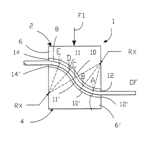
As shown ;n Figure lA, apparatus for breaking an optical
`fiber, comprises a fiber clamp which is generally referenced 1
and which is supported in a clamping frame 3, and a fixed frame
7 supporting a movable fiber holder 9.
The fiber clamp 1 comprises fiber clamping units 2 and 4
respectively, the units 2 and 4 comprising rigid blocks 6 and 6' `
respectively, made for example of metal. The blocks 6 and 6'
are formed with undulating confronting surfaces 10 and 10'
respectively, which are complementary with each other. There
are adhered to the surfaces 10 and 10', for example by means of
a suitable glue, resilient strips 8 and 8' respectively, made of a
non-fraying material, for exampl~ a synthetic felt, each strip 8
and 8' follow;ng the contour of the respective surface 10 or 10'
the strips 8 and 8' having confronting surfaces 11 and 11'
respectively. Each strip 8 and 8' having confronting surfaces 11
and 11', by virtue of the serpentine configuration of its
supporting sur~ace 10 or 10', has lengths of various radi; RX,
constantly spaced the points A to E on which, are identified in
Figure 1. The surface 11 is continuously convex from its right
hand ~as seen in Figure 1) end 12, through points A and B up
to point C, and is reversely contoured, that is to say concave,
from point C through points D and E, to its left hand ~as seen
in Figure 1) end 14. The surface 11' is continuously concave
from its r;ght hand (as seen in Figure 1) end 1? through points
A and B up to point C, and is reversely contoured, that is to
say convex, from point C through points D and E to its left
hand ~as seen in Figure 1) end 14'. Thus in each case, the
..
7 ,. , , ' ,~, . : . :
,' ,, ,~,, ~ , '
. ,' '' ~ .
' ' ~
~ ~7~ ~ 32~375
curvature of each resilient strip 8 and 8' and thus of its
confronting surface 11 or 11' is reversed at point C.
As shown in Figures lA to lC, the clamping frame 3 has
operating levers 5 for moving supports 2' and 4' for the units 2
and 4 vertically towards and away from one another between an
open position in which an end portion of an optical fiber OF can
be inserted between the surfaces 11 and 11' lengthwise of the
strips 8 and 8', and a closed fiber clamping position in which
the units 2 and 4 are shown in Fiyure lC. The levers 5 can be
operated, to apply a predetermined clamping force F1 to said end
portion of the fiber OF. The frame 7 has an operating handle
13 for moving the fiber holder 9 towards and away from the
fiber clamp.
For use with the apparatus, said end portion of the fiber
OF has formed, therein, for example by scribing or etching, a
sharpl V-shaped notch N, which is best seen in Figure lD, to :~
provide a weakened zone at which the fiber end portion can be
broken, as described below. The fiber OF with the notch N
formed therein, is passed through fiber holder 9 which is then
actuated securely to grip the length of fiber OF extending
therethrough, and the fiber holder 9 is advanced by means of
the handle 13, from a retracted position (not shown), to pass
the end portion of the fiber between the surfac~s 11 and 11',
with the units 2 and 4 in an open position (Figures lA and lB),
to position the notch N at point A as shown in Figure 2. In
Figures 2 to 7, the position of the notch N is indicated by a
broken line N and in Figures 2A to 7A by a full line N. Upon
closure of the units 2 and 4 (Figure lC), the force F1 ;s applied
to compress the fiber portion between the surfaces 11 and 11'.
The notched part of the fiber end portion is, therefore,
subjected to pure bending load as will be apparent from the
stress d;stribution indicated by compressive stress lines CS and
tensile stress lines TS in Figure 2A. The configuration of the
strips 8 and 8', at point A is such that said bending load is
applied to bend the fiber about the notch N, which is
uppermost, in the opposite sense to that
.-
" ; ~ ",
, ~ , , ~ :, . .
:` ` . : ' ;'' " : ' ' ' ~ `
~ -8- ~ ~2~3~
needed to cause the fiber to break at the notch N, that is to
say a sense wh;ch tends to close the notch N. No breaking
action therefore occurs at po;nt A. The fiber holder 9 is now
retracted by means of the handle 13 to apply a predeterm;ned
pulling force Pl (Figure 3) to pull the fiber OF in a left hand
(as seen in Figure 3) direction, so that it slides axial~y between
the surfaces 11 and 11', whereby the notch N is shifted from its
start location, namely point A, through points B, C and D, to
point E as shown in Figures 4 to 7.
When the force Pl is applied, w;th the notch at point A,
the fiber begins to move, the stress distribution in the fiber, in
the vicinity of the notch N, results mainly from the bending :
load, and to a small extent from the tensile load9 applied to the
fiber as indicated in Figure 3A. As the fiber continues to slide
between the surfaces 11 and 11', and the notch N is moved from
point A to point B, the bending load gradually decreases and
the tensile load gradually increases (Figure 4A). By the time
the notch N has reached point C, i.e. the reversal point of the
arcs of the surfaces of 11 and 11', the bending load has
decreased to zero and the stress distribution at point C is due
to pure tensile load (Figures 5 and 5A) which gradually
increased as the notch N was moved from point B to point C.
As the notch N is moved from point C to point D the bending - :
load on the notched part of the fiber is reversed, so that said
part of the fiber is bent gradually in a direction to break the
fiber at the notch N. At this time the tensile load on the fiber
also gradually increases tFigures 6 and 6A). As the notch N
moves from point D to point E, the bending and the tensile loads
in the notched part of the fiber gradually increase so as to be
in correct relation to each other at point E where the fiber
breaks, the stress distribution being such that there is minimal
local stress at a given break strength (Figures 7 and 7A),
whereby the speed at which a crack is propagated through the
fiber from the notch N, as the fiber breaks, does not exceed a
critical velocity of about one third of the speed of sound. As
the fiber breaks, the severed end of the length of fiber gripped
, .-
, , , , . ; ~ - - ~ -
- , . . ~; .~ .. ~ . ..
-~
., , . -,
-9- 1~2~375
by the fiber holder 9~ is pulled away from the severed end of
the fiber end portion ~etween the surfaces 11 and 11', so that
the severed end faces of the fiber cannot bear against one
another. When the fiber has been broken as described above,
the units 2 and 4 are returned to their open posit;on by means
of the levers 5, so that the severed end portion of the fiber OF,
can be removed from between the surfaces 11 and 11'.
Two phenomena influence the stress distribution in the
notched part of the fiber, as the notch N is moved from point A
to point E.
Firstly, the pulling force Pl causes a tensile load on the
notched part of the fiber as it slides betwe~n the strips 8 and
8'. The tensile load and the resulting stress in the fiber
increase gradually from point A (start of movement of the fiber)
up to point E (the break location of the fiber).
Secondly, due to the bending force, the compressive stress
in the upper part of the notched part of the fiber, that is say
in the vicinity of the notch N, and the tensile stress in the
lower part of the fiber gradually decrease to zero as the notch N
moves from point A to point C, at which latter point the
compressive and tensile stresses are reversed so that from point
C, tensile stress will occur in the upper part of the notched
part of the fiber and compressive stress in the lower part
thereof, both said stresses increasing until the notch N reaches
the break location, namely point E.
The stress distribution in the notched part of the fiber is
therefore as shown in Figures 2A to 7A. With the stress
distribution at the break location, shown in Figure 7A, there will
be little or no mist or hackle on the severed f1ber end faces,
because the crack propagation speed will not, as mentioned
above, exceed the critical limit of about a third of the speed of
sound. This stress distribution maintains the crack propagation
speed at its correct value to prov;de severed fiber end faces
with mirror type optical surfaces over the whole end ~ace area
because said local stress, which increases propagation speed is
at a minimum at a given break stress. If the crack propagation
. :, : ,,: . :.,, - - , , :
~ 3 ~ 7 ~
speed were to reach a value of about one third of the speed of
sound, the fiber surfaces which are being divided as a result of
the crack, would be split up by a multiplicity of fissures,
causing hackle preceded by mist. As the fiber slides between
the resilient strips, torsion resulting from the clamping of the
fiber is diminished or even avoided, so that the fracture angle
at the severed end faces is consistent whereby undesirable
reflection of light back into the core of the fiber where the
severed fiber end faces 16, are arranged in abutting, but
offset, relationship, as shown in Figure 8, is limited. In Figure
8, the fracture angle, which generally does not exceed 1, is
referenced A. The contamination of the end faces 16 by the
material of the strips 8 and 8' is reduced by making these strips
of a non fraying material, for example a synthetic felt.
Reference will now be made to Figures g to 15. Fiber
breaking apparatus according to this embodiment comprises a
fiber holder 18 similar to the fiber holder 9 described above,
and being similarly mounted. The fiber holder 18 is movable
towards and away from a fiber clamp, which is generally
referencPd 20, and which comprises a movable upper fiber
clamping unit 22 and a movable lower ~iber clamping unit 24.
The unit 22 comprises a rigid block 26, made for example of
metal, and having a radiused lower surface 28 which is smoothly
bowed towards un;t 24 and to which ;s adhered a resilient strip
30, made of a non-fraying material, for example a synthetic felt,
and which follows the contour of the surface 28 so as to have a
fiber engaging surface 32 having a radius R1 ~Figure 9). ~he
unit 24 comprises block 34, which, like the block 26, is rigid
and may be made of metal. The block 34 has a first rectilinear,
horizontal, surface portion 36 which extends from the right hand ~ --
(as seen in FigurQs 9 to 15), end of the block 34 and merges
with a shorter, downwardly chamfered, second surface portion 38
proximate to the left hand (as seen in Figures 9 to 15) end of
the block 34 and extending obliquely away from the surface 28,
so that near the left hand (as seen in Figures 9 to 15) end of
the fiber clamp 20, the surfaces 28 and 38 diverge fro~ one
:, . .. ; ,- .
.., :, . ..
;
" ~ ~ ,. .
-
: i,
-ll- 132~3~
another in the direction of the fiber holder 180 Fixedly adhered
to the surfaces 36 and 38 and following the contours thereof, is
a resilient strip 40 made, for example, of a synthetic felt. The
strip 40 thus has a fiber engaging first surface portion 42
following the contour of the surface portion 36 and thus being
horizontal and rectilinear, and a second fiber engaging surface
portion 44 following the contour of the surface portion 38, the
surface portions 42 and 44 cooperating to define a radius R2
(Figure 9) bowed towards the surface 32, the surface 32 and the
surface portion 44 diverging in a direction towards the fiber
holder 18. The units 22 and ~4 are supported by a clamping
frame, not shown, which may be similar to the clamping frame 3
described above, and having s;milar operating levers.
Figure 9 shows the apparatus in a starting position in
which the fiber holder lB, through which an end portion of an
indefinite length of optical fiber OF has been passed, has been
actuated to clamp the fiber against movement relative to the fiber
holder 18. In the starting position, the fiber holder 18 is in a
horizontally retracted position remote from the fiber clamp 2~,
the units 22 and 24 being in an open position so that the surface
32 and the surface portions 42 and 44 of the strips 30 and 40
respectively, are spaced from one another to receive between
them, the end portion of the fiber OF. The fiber holder 18 is
then advanced, as shown in Figure 10, from its starting
posit;on, towards the fiber clamp 20 in the direction of the arrow
B in Figure 10, to an extent limited by an adjustable fiber
holder stop S1, so that the fiber end portion is inserted between
the strips 30 and 40, with a notch N, similar to that shown in ~:
Figure lB, which was previously formed in the fiber end
portion, positioned approximately mid-way between the ends of
the strips 30 and 40 as determined by the position of the fiber
holder stop S1. The clamping unit 24 is then raised to an
extent determined by an adjustable stop S2 so that the fiber end
portion is lifted slightly as shown in Figure 11. The adjustment
of the stop S27 iS not, however, critical, being of the order of
plus or minus 0.2 mm.
' ' '` 1 ' ' ' ' ~ "'~ ' . '
-12- ~3~7~ ;
After the unit 24 has been raised as described above, the
unit 22 is lowered towards the unit ?4, as shown in Figure 12,
by means of said clamping frame to exert clamping force F
against the unit 24, which is held by the stop 52 against
downward movement. The fiber end portion so clamped, is
thereby bent about the notch N, between the surface 32 of the
strip 30 and the surface portion 42 of the strip 409 in a sense
opposite to the sense of bending that ;s needed for breaking the
fiber end portion, by virtue of a configuration of the surface
32, the notch N being uppermost. The value of the force F is
not critical, being, for example, 10 Newtons, plus or minus 2
Newtons.
With the fiber end portion clamped between the strips 30
and 40, the fiber holder 18 is retracted as shown in Figure 13,
to apply a pulling force P to the fiber end portion, the value of
which force is selected in accordance with that of the force F
and the co-efficient of frietion between the fiber end portion and
the strips 30 and 40, so that the fiber end portion slides there
between. `When the notch N reaches a critical zone Z, where the
surface portions 42 and 44 of the strip 40 merge at the radius
R2, the fiber end port;on is gradually bent about the notch N in
a sense opposite to the first mentioned sense so that the fiber
end portion is broken at the notch N, a correct relationship
between the bending and the tensile loads having been achieved
(as at point E in F;gures 7 and 7a3.
By correct adjustment of the stop S2 and the value of the
force F, the fractured end faces of the fiber end portion will
each have a mirror type surface extending over its whole area
and a small angle of facture Y as indicated diagramatically in
respect of the severed fiber end face 16' shown in enlarged form
in Figure 14. The fiber end portion having bPen broken, the
holder 18 is returned to its starting position as shown in Figure
14 so that the severed end face 16 of the fiber length held by
the holder 18 is pulled away from the severed end face of the
fiber portion remaining clamped between the str;ps 30 and 40.
The units 22 and 24 are then moved to their open position, as
, ~ , . ~ j ~, .
- .: , .. , :, . - . - : ,
.: . ~. , . ., , :
- - ,
~:
-13- ~32~3~ :
shown ;n Figure 15 for a further cycle of operation of the fiber
breaking apparatus, which is carried out when the loose fiber
portion has b~en removed from the fiber clamp 20.
During each cycle of operation of the apparatus shown in
Figures 9 to 15, the stress distribution in the vicinity of the
notch N will be as shown in Figures 2A to 7A. In the optical
fiber breaking method described above with reference to Figures
9 to 15, there are two main parameters7 namely the positioning
of the unit 24 by the stop S2 and the magnitude of the force F.
These parameters are not, however, critical and both can be
readily adjusted, the radii R1 and R2 also not being critical.
The notch N should, however~ be sharp and Y shaped.
The method may alternatively be carried out by maintaining
the fiber holder 18 against the stop S1 with the force F applied
to the units 22 and 24 and moving the fiber clamp 20 away from
the fiber holder 18; instead of retracting the latter away from
the former. In this case, the fiber will slide between the strips
30 and 40 in exactly the same way as in the method described
with referenee to Figures 3 to 15 and the fiber will break in the
same way.
Optical fiber breaking methods and apparatus described
above, have the advantages that the severed end faces of the
fibers are optically smooth throughout, the facture angles are
small and consistent angles, angles of less than 1" being
achievable because little or no torsion is applied to the f;ber.
At the same time, the parts of the apparatus are simple and easy
to adjust and the parameters are not critical. Any little
contamination that may be formed on the severed fiber end faces
is readily removed by means of adhesive tape.