Note: Descriptions are shown in the official language in which they were submitted.
1 3 2 ~
INl'ERMITTENT ~ORK CONVEYING APPARATUS
Background Of The Present Invention
This invention relates to an intermittent
work conveying apparatus for transport of a series of
parts through equispaced work stations and particularly
to such apparatus requiring multiple directiona-l
positioning of the work.
In various production processes, an article
or work product, hereinafter generally referred to as
the "part", is moved through a series of work stations
for processing of the finished part. In many
applications, the work on the part at each work station
is automatically established and in some instances, a
relatively short period of time may be allotted at each
station. A typical example of an automated line is an
electrocoating paint system wherein the part is
sequentially treated to receive a paint application
with the article sequentially processed to established
a pre-determined coating thickness and finally
processed to dry the applied coating. Each step in the
process can be accomplished in relatively short period
of time. Thus, the part may typically be processed at
each station in a maximum of two to three minutes. The
part is moved through the sequential positions or work
stations in a stepped manner in one system and in a
continuous uninterrupted manner or movement in another
system. Continuous paint lines move the part through
pretreating tanks, coating tanks and final treating
tanks by an in-line conveying system. Generally,
lengthy treatment and paint tanks are required to
accommodate the sequential and continuous movement
through the several stations. Generally, the prior art
discloses a continuous conveyor of a chain type with
the path of the conveying mechanism providing for the
movement of the product in a rather smooth curved path
into and from the various treating and painting
tanks Although satisfactory painting has been
provided using such standard systems, the systems are
large, reguiring significant floor spaced and are
relatively costly. Thus, the tank or container
structure is very large to accommodate the continuous
movement of the part through the tank structure while
maintaining the product within the appropriate
environment and atmosphere for product treatment. Such
systems also are relatively costly because of the
necessity of using large quantities of materials, such
as paint, water and other chemicals associated with the
large treatment baths or tanks.
Although an intermittent stepped system can
be used to reduce the size of the structure, the
movement of the product then requires the appropriate
lifting and transfer of the product from one tank to
the other. Such a system using conventional conveying
mechanisms such as chain-type conveyors and the like
also present a complex and costly mechanism.
Further, in view of the short cycle time
required in any given station or tank, the loading and
unloading of the part in an intermittent system
presents further complications. Either a significant
number of personnel is required for manual loading and
unloading of product or various complex and costly
loading and unloading mechanisms have heretofore been
required.
Generally, present day technology has
involved substantial investment in the machinery for
electrocoating systems as well as significant
maintenance cost and operating personnel cost,
particularly related to the loading and unloading of
parts and products.
l~l
Various articles and products can of course
be coated with electrocoating processes. For example,
cabinet panels and any other product which can be
provided with an appropriate charge can be treated with
an appropriate coating.
The short cycle time of any given station
provides for relatively large production which
minimizes the part cost and has justified the
substantial investments required in the process
apparatus.
There is however a very significant demand
for improved apparatus permitting improved cycle times
as well as more effective and less costly loading and
unloading mechanisms and related transfer apparatus.
Summary Of The Present Invention
The present invention is particularly
directed to an intermittent or stepped transport
apparatus having an improved conveying mechanism for
the sequential stepped placement of a part into
successive work stations, with the several parts at the
several stations moving simultaneously into and from
the stations and then simultaneously moving
sequentially to the next adjacent station. In
accordance with another significant feature of the
present invention, an improved loading and unloading
apparatus is provided to maintain maximum production.
Thus, the loading and unloading apparatus is specially
built to permit the loading and unloading within the
maximum cycle time of any given station which for
example, in an electrocoating system is typically two
to three minutes.
More particularly, as applied to an
electrocoating line, for which the present invention
has been particularly constructed and adapted, a
sequential series of tanks or stations are provided in
r ~ ~
immediately adjacent relationship. The part is passed
intermittently from one station to the next with all
parts held effectively stop at the station for the
necessary processing period. An over/under sequential
conveyor system is provided, with a drying mechanism
mounted in overlying vertically spaced relation to the
paint applying line. The over/under system is typical
of a loop system, and other organization such as
horizontal spacing or combined horizontal and
vertically spacing of the conveyor or transport system
may be used with the present invention. In accordance
with the present invention, the part conveying
structures includes a segmental conveying mechanism
with equal segments for each part for conveying of the
part from one station to the next station, with each
conveying segment being movable in at least two
different directions for changing the directional
movement of the part. The segments are releasably
engaged for linear movement by a drive unit such as
push drive units.
More particularly, in a practical and unique
embodiment of the present invention, the segments
include a plurality of slide bar units slidably mounted
in a pair of parallel tracks, rails or other guide
elements. The slide bar units include releasable
couplings for receiving of a work carrier. In a
practical embodiment, each slide bar unit carries an
upwardly opening load support member. A part or part
carrier member spans the spaced rails and is adapted to
rest in the support members for movement of the part
with the slide bar units. At the entrance and
discharge end of the rails, transfer units are provided
for moving of the slide bar units from the rails. ~ith
the slide rails aligned with the transfer units, the
slide bar units are transferred from and to the slide
1 3 ~
rails, and can then be moved in the same or some other
direction. In the over/under coating line, transfer
rails with the slide bar units therein are moved
vertically. Thus, at the discharge end of the paint
S applying line, the transfer rails move upwardly into
alignment with the conveyor rails of the dryer unit.
The slide bar unit is then moved into the dryer
conveying rails and moves intermittently through the -
drying chamber. At the end of the drying apparatus,
the part and slide bar units move to a drop rail unit
which deposit the part into an automated load/unload
system.
In the preferred construction, the
load/unload mechanism or unit includes a unique take-
away conveyor or transport unit having suitable
supports for the load carrier member which is
releasably supported on the slide bar units. The slide
bar units are placed in a transfer position at the
load/unload system or unit for automatic transfer of
the load.
A part change apparatus includes a pair of
pivoting guide rails or tracks. A carriage unit is
mounted on the tracks and include side members which
extend upwardly, terminating in the upper end in
transfer units. The carriage is coupled to a powered
mechanism for movement between the entrance end of the
coating conveyor and a part source unit. The pivoting
movement permits the dropping of the transfer rails and
the carriage. Thus, to unload or load a part, the
transfer tracks are first positioned in a raised
location and moved into alignment with the transfer
position of the coating rails. The carriage unit is
moved into underlying alignment with the slide units.
The coating rails drop and the part carrier members
drops onto the carriage, which then moves to the
--6--
r, ~ ~
source. Thus, the transfer to and from the slide bar
unit is created by relative vertical movement between
the carriage and the rails. The tracks are pivoted
down to unload the part carrier members onto a
conveyance which removes the finished parts and aligns
a new load carrier member and part with the carriage.
The carriage tracks are raised to pick up the load
carrier member with the new part and then moved to
place the part onto the slide units.
Although described using slide units and
slide rails, the load segments can of course be wheeled
or otherwise supported devices mounted on or in a
suitable track unit. In a practical application
applied to the coating line, the slide units were
lS formed of a box-like channel of the appropriate desired
length. Brass shoes were secured to the bottom side of
the tube to slidably support the slide for movement
through the support rails or conveyor rails,
In the preferred construction, the individual
segments are slidably mounted along a common rail
structure. The common rail structure is mounted at a
plurality of lift stations or vertically moving
stations by a supporting chain and sprocket. The chain
in turn is coupled to a positioning slide extended
throughout the length of the unit. The sliding of the
rail causes the chain to move over the sprocket for
raising and lowering of the slide for corresponding
positioning of the work carried thereby.
The present invention thus provides for the
individual load segments slidably mounted within a
suitable slide structure for sequential and
intermittent movement between the several work stations
with appropriate lateral transferring conveyors for
movement of the work piece from one part of the line to
another and for movement of the work piece into and
1 3 ~
srief Description O _ he Drawings
The drawings furnished herewith generally
illustrate the best mode presently contemplated for
carrying out the invention and are described
hereinafter.
In the drawings:
Fig. 1 is a side elevational view of a slide
rail conveyor system constructed in accordance with the
teaching of the present invention;
Fig. 2 is a plan view of Fig. l;
Fig. 3 is an enlarged sectional view taken
generally on line 3-3 of Fig. 2 and illustrating a
construction of the slide rail conveyor system shown in
Figs. 1 and 2;
Fig. 4 is a vertical transverse section taken
generally on line 4-4 of Fig. 3; and
Fig. 5 is an exploded pictorial fragmentary
view of the elements shown in Figs. 3 and 4.
Description Of The Illustrated Embodiment
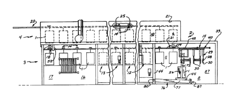
Referring to the drawings and particularly to
Figs. 1 and 2, a plurality of components or parts 1 are
shown passing through a coating apparatus 2
illustrating an embodiment of the present invention.
Each of the parts 1, although shown as an identical
member, may of course have any different
configuration. The only limitation on parts 1 is that
they must fit within a series of processing or work
stations which are presently described and further must
each be adapted to receive a similar treatment and
coating. The present invention has been particularly
applied to an electrocoating system in which a coating
is applied and dried in a continuous processing line.
The illustrated coating apparatus is an under-and-over
system including a bottom or lower coating section or
line 3 and a top or upper drying section or line 4. A
--8--
1~2~r ~
lift section 5 is located at the common downstream end
of the coating section 3 and the upstream end of the
drying section 4. The lift section S provides for
automated transfer of the parts 1 from the coating
section 3 to the dryer section 4. The drying section
terminates in a drop station or section 6 at which the
part 1 is lowered downwardly from the drying section
into a transfer section 7. The finished part 1 is
lowered into the transfer station or section 7 which
includes an automated transfer apparatus 8. The parts
1 are thus moved into and from the circulating path of
the lines 3 and 4 at section 7 by apparatus 8. The
present invention is particularly directed to the
construction of the support and transfer of the parts 1
using a slide rail concept and system for supporting
and moving of the individual parts through the various
portions of the system and to the automated apparatus 8
for transfer of parts 1.
Generally, in accordance with the illustrated
embodiment of the present invention, the coating
section 3 includes an elongated continuous slide rail
assembly 9. The slide rail assembly 9 is vertically
movable between a raised load transport position or
level 10 at which the various parts are moved into and
through the coating section 3. The parts 1 are shown
in full line illustration in the raised level. The
rail assembly 9 is adapted to reciprocate vertically
and drop the parts to a treating or coating position or
level 11, as shown in phantom. In the lowered
positioned, the parts 1 are dropped into various
treating stations and apparatus. For example, a
typical coating line 3 may include eight stages or
pretreat wash stations 12, consisting of 8 different
work stations, only 2 of which are shown in Fig. l and
2, and 4 coat and rinse stations 13 of which only a
1 3 ~ [.'~
coat station and a final rinse station are shown. The
coating section 3 includes the multiple station
transfer lift section 5, shown including only a first
fitter station and a lift station for purposes of
simplicity in the illustrated embodiment of the
invention. Each of the illustrated several stations in
the generally rectangular work or processing area is
adapted to accommodate the part 1 and supporting
mechanisms. The transverse center lines of the work
stations 12 are spaced by a constant distance. The
parts 1 are sîmilarly spaced by the distance between
the successive stations within the system and so held
as they move through the rail assembly 9.
Each part 1 is particularly supported by a
separate slide unit 14 slidably disposed in the rail
assembly 9. Each slide unit 14 is of a similar
construction and corresponds in longitudinal length
within the rail assembly 9 to the corresponding length
of the work stations 12. By pushing on the upstream
end of the slide units 14 within the rail assembly 9,
all units 14 and parts 1 are moved the appropriate
distance. A slide push unit 15 is mounted to the
upstream end of the rail assembly 9 and operatively
engages the first slide rail unit 14 at the upstream
end of the assembly at the transfer section 7. The
push unit 15 moves into the rail assemby 9 for a
distance equal to the length of a slide unit and thus
simultaneously steps all slide units 14 and supported
parts one work station step for moving of the parts
into alignment with the next work station. The forward
or downstream most part 1 aligned with the last work
station is moved from the coating section 3 into and
through the lift section 5 for automatic transfer to
the drying section 4 in appropriate sequence.
--10--
~t ~
The illustrated lift section S includes
filter station 16 and a downstream lift unit 17. Thus,
in the seguence, the parts are moved sequentially
through the station 16 and then into the lift unit
17.
The lift unit 17 includes a separate lift
rail assembly 1~ adapted to be aligned with the rail
assembly 9. The separate rail assembly 18 is supported
for vertical movement and is of a length corresponding
10 to the length of a slide unit 14. Thus, as a slide
unit 14 is moved into the rail assembly 18, the part 1
is mounted for vertical movement from the coating
section 3 into alignment with the drying section 4.
The drying section 4 includes a fixed
15 horizontal rail assembly 19 for receiving of the slide
unit 14 from assembly 18.
A dryer push unit 20 is mounted to the top or
upper level of the drying section 4 and to the upstream
end of the rail assembly 18 and dryer rail assembly
20 19. The push unit 20 transfers the slide unit 14 from
rail assembly 18 into aligned rail assembly 19 and thus
moves the parts in corresponding timed relation through
the drying section 4 in corresponding timed relation to
the parts moving through the coating section 3 and for
25 a corresponding horizontal length or distance. The
downstream end of the rail assembly 19 terminates at
the drop station or location 6. A vertically movable
drop rail assembly 21 is located at the drop station
and is vertically movable between alignment with the
30 dryer rail assembly 19 and the coater rail assembly
9. It again has a length corresponding to the length
of a slide rail unit 14. This provides for lowering of
a part 1 discharged from the drying section 4 into the
plane of the coating section 3 and into the transfer
35 section 7 of the system.
The transfer section 7 includes a finished
part station 22 aligned with the drop section 6 and a
load change station 23 immediately adjacent the
upstream end of-the coating section 3. The transfer
stations 22 and 23 are aligned, with the drop rail
assembly 21 of the dryer section 4 located in the same
plane as rail assembly 9 when in the raised transport
position level 10. The load/unload transfer apparatus
8 automatically provides for appropriate transfer of
the parts 1 from and to a slide unit 14 at station 23
tv complete a work cycle, which is repeated for
continuous production.
The main or coating rail assembly 9 extends
upstream from the first work station 12 into the
station 23 of the transfer section 7. In the retracted
position, assembly 9 terminates in precise and close
alignment with the drop rail assembly 21. The push
unit 15 for the coating section 3 moves through the
aligned drop rail assembly 21 and pushes the slide rail
unit into the aligned rail assembly 9 thereby
simultaneously moving the slide units 1~ in the rail
assembly 9 into the coating section 3. The finished
part and associated slide unit 4 is then located in the
transfer station 23 for removal and replacement by
apparatus 18.
In the illustrated embodiment of the
invention, the rail assemblies each include laterally
spaced supporting rail structures as more fully
developed hereinafter. Separate slide units 14 are
mounted in each of the rail assemblies. The part 1 is
carried by a laterally extended load carrier member 25,
shown as a rod member, the opposite ends of which are
releasably secured to slide units 14.
A load/unload carriage 26 of apparatus 18, in
the form of a truck-type unit, is movably mounted at
-12-
L ~ ~ '3
the transfer section 7. Carriage 26 is aligned with a
slide unit 14 at the transfer change station 23 and
relative vertical movement of the rail assembly 9
transfers the load member 25 to or from the slide unit
14. The carriage 26 is horizontally movable for moving
of the load carrier member 25 and associated part to or
from the load/unload station. Movement of the carriage
26 vertically orients the load member and part with
respect to an automated load/unload source apparatus 27
for automatic removal of the finished part 1 and
replacement thereof with a new or unfinished part 1.
The source apparatus illustrated is a
carrousel-type overhead conveyor including a plurality
of recirculating load supporting brackets 28. The
source apparatus 27 includes a plurality of load
carrier support brackets 28 pivotally secured to an
endless chain unit 29 for movement in a horizontal
plane. A separate bracket 28 is provided for each
carrier member 25 and includes a pair of spaced hook
members 30. The carrier member 25 is placed with hook
member 30 by movement of carriage 26 to remove the
finished part 1 and removed from the hook members 30 of
the next bracket 28 by opposite movement of carriage 26
to establish the desired automated interchange. Each
bracket 28 is slightly longer than the load carrier
member 25 and includes the pair of spaced depending
hook members 30 adapted to support and carry the load
carrier member and associated part 1 from and into
alignment with the carriage 26. A spaced main part
source location is provided in spaced location to the
carriage location where the finished part is removed
and a new part 1 and is introduced into the source
apparatus. Ample time is provided for convenience
loading and unloading of the parts 1 during the period
between the transfer of parts throughout the
-13-
13~,~ r~
load/unload system. Thus, the source apparatus can be
loaded and reloaded during the period that the work or
parts are removed from the section 7 and during the
part processin~ time in each cycle.
Thus, briefly summari~ing the system before
describing the various elements in detail, parts 1 are
automatically transferred from and to the load/unload
carriage. In the load movement, the part is carried on
the upper end of the carriage which i5 then moved
forwardly and over the rail assembly 9. The load
carrier member is located in alignment with the
location of the slide unit 14 in the change location 23
when the rail assembly 9 moves upwardly, the load
member 25 with part 1 in place is picked up by the
aligned slide unit 14 for transport through the
system. ~ith the insertion of a new part 1, the push
units 15 and 20 are simultaneously actuated to
simultaneously move the newly loaded part into the
first station of the coating section or line and
simultaneously moving all prior loaded parts the
corresponding precise distance to align it with an
appropriate new section or stage of the coating section
into an appropriate position in the lift or drop
sections and through the dryer section. The parts are
held in each stage and position for the fixed working
time, which in a practical electrocoating line may be
on the order of 2 to 3 minutes.
During the fixed time period for processing
of part 1 in the several stations, the finished part 1
. is removed from the processing line and transferred to
the carriage, transferred to the source apparatus where
a new part is loaded onto the carriage and transferred
back into alignment with the lowered rail assembly 9 in
alignment with the last slide unit 14. The load member
with the new part is thus aligned with the available
14 ~ ~h ~3~
slide unit located in the upstream most end of the rail
assembly 9. The new load carrier member 25 is held in
position and picked up as the rail assembly 9 rises.
During the same processing time, the last or finished
part has been moved into the drop section of the drying
section, and lowered into the unloading position
aligned with the coater push unit 15. The apparatus is
again in position to initiate a new operating cycle upon
termination of the treatment of the parts at the several
stations or stages.
The present invention is directed to the
provision of the slide rail conveyor particularly
including the individual slide units or other individual
segments for each part 1 with the control timed moYement
related to the processing time at the plurality of work
stations. In addition, in the illustrated embodiment of
the invention, the automated load/unload apparatus
provides a further and unique apparatus for the automated
load and unloading of parts 1 with respect to the slide
rail conveyor. The illustrated embodiments of the
loading and unloading unit are presently described in
detail. The load and unload conveyor apparatus for
transfer of parts 1 to and from the loading/unload
apparatus may be of any desired or suitable construction.
The apparatus is shown and briefly described. A full
description is presented in the co-pending Canadian
- application of the present inventor entitled "Part
Indexing And Positioning Apparatus" and filed on even
date herewith with Serial No. 614,751.
More particularly and as more clearly shown
in Figs. 3 through 5, the illustrated slide rail
assembly 9 includes first and second laterally spaced
~imilar rails 31 extending throughout the length of the
coating section 3, the transfer section 5 and 6 and
into the change station 23 of the transfer section 7.
~,
.. . ..
-15-
- 1~2~ ~5
Each of the rails 31 is similarly constructed as a box-
like channel having a longitudinal upper slot 32. The
rails 31 are mounted in a common horizontal plane for
simultaneous and corresponding movement, as more fully
described as hereinafter. Each of the horizontally
mounted rails 31 is adapted to support the
corresponding slide rail units 14 for transport of
parts l through the apparatus and particularly the
coating section 3.
Each slide unit 14 includes a pair of
similarly spaced slides 33 in the form of a box-like
member of a length correspondingly precisely to the
length of each stage or work station of the coating
section 3 and transfer section 7. Front and back shoes
34 are secured to the underside of the box member or
slides 33. The cross section through the box member
and interconnected slide shoe closely complements the
internal cross section of the box section of the
corresponding rails 31. A load member 35 is secured to
the top center of each slide 33 and is located
centrally of the longitudinal length of each slide
33. Each load member 35 is similarly constructed as a
plate member welded or otherwise secured to the slide
33 and projecting upwardly through the slot 32. The
upper edge of the member is provided with a V-shaped
opening 36 for receiving and supporting the aligned end
of the load carrier member 25.
The carrier member 25 include a round rod 37
spanning the assembly and resting in the V-shaped
opening 36. Flat end walls 38 are welded or otherwise
secured to the ends of the rod and project outwardly
slightly thereof to establish lateral location and
support of the rod to the load members 35. The wall~
38 are located accurately on the slide members 33 and
hold the part 1 for accurate movement into and from the
work apparatus at the various stages or stations.
-16-
- ~32~'3
The coater push unit 15 is secured to the
frame structure 39 of the apparatus and includes a
hydraulic cylinder 40 mounted to the frame structure.
A piston rod 41 projects outwardly of the cylinder unit
for reciprocation in a horizontal plane. A pair of
laterally spaced push rods 42 are secured to the piston
rod with a suitable guide and supporting structure 43
for locating of the push rods in alignment with the
spaced rails 31 in the raised position. The cylinder
40 is connected to a suitable pneumatic or hydraulic
supply for reciprocal movement of the piston and
attached rods 42. In the retracted position, the ends
of the push rods 42 are located upstream of the drop
location and thus upstream of the lowered position of
the drop rail assemblies 18. Extension of the piston
rod 41 and the push rods 42 force the rods 42 to move
through the rail assemblies, moving the slide units 14
from the drop rail assembly 18 into the aligned rails
31, with a corresponding stepped movement of the slide
units 14 and the associated parts 1 in the rail
assembly 9.
The slide rails 31 of assembly 9 are mounted
for simultaneous vertical movement between the raised
or top transfer level 10 and the bottom or lowered work
level 11.
The rails 31 are similarly supported by a
plurality of vertical support posts 44 of the frame
structure 39 and are longitudinally spaced throughout
the length of the apparatus. Each support post 44 is a
post like assembly including a fixed support rigidly
affixed to the frame structure 39 and definin~ a slide
rail or support. A slide 46 is secured to each of the
rails 31 of assembly 9 and project into the support
unit 44 to establish a guided vertical movement of the
corresponding rails 31. The slides 44 are connected b~
r, ~ ,3
a cross beam 45. Positioning chain units 47 are
provided at each of the supports 44 to one side of the
assemblies 9~ The one end of the chain is secured to
the one slide 46 at each side of the assembly. The
chains 47 extends upwardly and then horizontally over
fixed sprockets 48. The outer end of each chain 47 is
fixed to drive rails 49 for moving of the chains
horizontally to thereby lower and raise the rails 31.
A powered cylinder unit 50 is mounted to a frame
structure and includes a piston rod extended
forwardly. The piston rod is attached to a member
connecting the drive rails and is operative to
reciprocate and move the associate chain units for
positioning of the rail units, providing guided
movement of the rails assembly 9. The continuous rails
31 provide the synchronized and necessary movement of
the work parts 1 between the raised transfer position
or level 1 and the lowered work position or levels
11. A switch control unit 51a is shown mounted
adjacent the rail 49 to selectively reverse the rail
movement at the lowered level lO. The unit 51a jogs
the part 1 within the operative station for improving
of the coating process.
The lift section 7 which includes the rail
assembly 18 is actuated in timed sequence with the
coating section 3. The rail assembly 18 includes a
pair of fixed rails 52 interconnected for simultaneous
vertical positioning of the rails 52. As shown most
clearly in Fig. 2, for the assembly 21 a hydraulic
cylinder unit 54 is mounted to the frame structure and
includes a piston rod unit 55 coupled to the rails 52
with chains 55a for vertical positioning of the rails
52 of assembly 18 between the alignment with the rail
assembly 9 and the rail assembly 19 of the dryer
section 4. It thus provides for selectively transfer
-18-
1~ 2 ~
of the parts 1 from the coating section 3 into the
drying section 4. The drying section push unit 20 is
constructed gene-rally in accordance with the
construction of the coating section push unit 15 and
includes a hydraulic cylinder unit 56 with a pair of
pusher rods 57 interconnected to each other and the
piston rod of the pusher unit 20. The push unit 20 is
actuated in timed relation and in synchronism with the
push unit 15 of the coating section to provide for
synchronized movement of the parts 1 through the
coating section 3 and through the drying section 4.
The rail assembly 19 for the drying section 4
is similarly constructed to that of the coating section
but with rails 60 fixedly mounted in a common
horizontal plane. The slide units 14 and parts 1 are
moved through a single plane in the drying section for
appropriate seguential processing and dryiny of the
coating and sequential discharge into the drop section
6. Thus, at the end of the drying section, the slide
rail units 14 move into the drop rail assembly 21
including a pair of rails for vertical positioning,
with a construction corresponding to assembly 18.
The part 1 is thereby moved downwardly into
alignment with rails 31 and transferred forwardly into
the transfer location immediately adjacent to the first
stage of the coating section 3 for movement and
interchange for a new part 1 through the use of the
load/unload apparatus and particularly carriage 26.
More particularly, referring to Figs. 3 and
4, the carriage 26 is generally a ~-shaped member
having a rigid support beam or base 70 extended
laterally of the apparatus. Vertically upstanding side
walls or brackets 71 project upwardly from the base
70. The upper ends of the brackets 71 are rigid plate-
like members having upper load arms 72 adjacent to a
--19--
13~
side of the rails 31, respectively. The upper ends of
the arms 72 are similarly formed with a V-shaped
opening 73 which open upwardly. The arms 72 are spaced
in accordance with the length of the rod 37 to receive
the carrier rod 37, with the end walls 38 of the rod
located immediately outwardly of the each of the
corresponding plates 72 and the slide units 14. Thus,
the arms 72 accurately support the load carrier rod 37
centrally of the rails 31 with the part 1 depending
downwardly therefrom between the rails 31. The ~-
shaped carriage 26 defines a rigid supporting structure
for movably supporting of the part 1 and suspended from
the support rod.
The U-shaped carriage 26 is supported by a
pair of laterally spaced trucks 74 and 75 which in turn
are mounted on the pair of laterally spaced rail or
track units 76 and which extend outwardly or upstream
beneath the transfer load/unload stations 22 and 23.
Each track unit 76 is similarly constructed
of a heavy supporting box beam 77 extending throughout
the length of the carriage movement.
The upper edge of the track unit 76 includes
an inverted V-track 78. The trucks 74 include truck
wheels 79 and are secured to the ends of the cross beam
of the carriage. The wheels 79 have a V-shaped edge or
face groove and rest on the V-tracks for movement along
the beam.
The track beams 77 are pivotally supported at
the downstream end adjacent to the transfer location
23 on a laterally extended pivot shaft 80. The beams
17 extend rearwardly or outwardly from the pivot shaft
80 to the conveyor source apparatus 27.
The carriage 26 is connected to a hydraulic
cylinder unit 81 mounted between the beams 77. The
cylinder unit 81 includes an internal piston unit
D
-20-
- 132~
secured at the opposite ends of the unit 81 to a cable
82 and 83. The one cable 82 extends over a guide roll
84 and is secured to the carriage 26 as at coupling
85. The second cable 83 is similarly mounted to the
opposite end ofthe cylinder unit 81 over a guide roll
86 and secured to the carriage 26 at coupling 85.
Reciprocation of the cylinder unit 81 to reciprocate
the carriage 26 between the two operative locations.
A second cylinder unit 87 includes a piston
rod 88 coupled by a bracket 89 to the outer cross brace
90 of the tracks to raise and lower the tracks and
thereby to raise and lower the carriage. Retraction of
the piston rod 88 results in the dropping of the tracks
to lower the carriage and thus the load arms 72 at the
source apparatus 27.
The piston rod 88 is extended to raise the
carriage 26 at the transfer station 23 such that the
upper ends of the carriage load arms 72 and
particularly the V-shaped openings are just above the
horizontal plane of the slide units 14 with assembly 9
in the top or raised transfer position. Thus, with a
finished part 1 placed in the transfer station 23 and
supported by slide units 14, the movement of the
carriage 26 with rails 31 at the transfer location
results in alignment with a finished part 1 and
supporting slide units. When the rail assembly 9 moves
downwardly to relocate and lower parts 1, the finished
part 1 is transferred to the carriage 26. The cylinder
unit 81 is actuated to carry the carriage 26 and part 1
from the transfer station 23 to the source apparatus
27. The exchange thus occurs at the source apparatus
27 with the finished part removed, and a new part and
its load member inserted on the carriage 26. The rod
37 of carrier member 25 is aligned with the openings 91
of the hook member or brackets 28 with the carriage 26
1C~
at station 23 and with finished part 1 on the carriage
as shown in phantom in Fig. 3. Cylinder unit 81 is
actuated and moves the carriage to source apparatus 27
and located the rod 37 within the opening 91 at which
time cylinder unit 87 is actuated to lower the track
beams 77. The arms 72 of carriage 26 move below the
hook members 30 and deposit the carrier member 25 with
part 1 to the hook members 30. The brackets 28 are
indexed one unit or step to remove the finished part 1
and align a bracket 28 with a new part 1 with the
dropped carriage, as shown in Fig. 3. The track beams
77 are then raised to pick up the new carrier member 25
and the new part 1. The raised carriage 26 is returned
to the forward position and station 23 with the carrier
member 25 passing over the rails 31 and into alignment
with the slide rail unit 14 in the lowered rails 31.
The load carrier member 25 is picked up by the slide
units 14 when the rails 31 are raised to the transport
level 10 for subsequent cycling through the apparatus.
The present invention particularly in the
illustrated embodiment establishes a continuous stepped
movement of work products through a series of work
stations in a closed loop with a relatively low cost,
long life and reliable transport and conveyor system.
The components are readily formed using present day
technology and are rugged, reliable and long life
elements which are particularly adapted to commercial
production environments. The apparatus requires
minimum maintenance and is readily controlled through
simple logic control systems including simple relay
logic. Obviously, microprocessor based controls can
also be readily provided where desired.
Although the slide units are shown formed as
elongated bar-like members with special slide shoes,
any other suitable elongated slide-like member can be
-22-
13~ ~ r1~J
provided. In addition, the unit can readily employ
wheeled slide units such as trolley type units. Thus,
the illustrated elongated bar members could be provided
with fore and aft wheel structures to establish a
rolling support for the slides. Thus, as used herein,
the definition involving "slide" is used generically to
cover any form of an elongated fixed rigid device or
member which will provide a fixed stepped movement in
response to the forced movement at one end of the
series of separate devices for carrying of the
individual load units.
Although illustrated with a single support
unit per slide bar, each slide bar can be provided with
a plurality of the upwardly opening units or other
suitable releasable support longitudinally spaced along
the bar. A load cross bar would then be deposited
within each unit for simultaneous corresponding
transfer of a plurality of loads through a line. In
such a system, the load interchange apparatus can be
similarly constructed to provide for the simultaneous
movement of all of the loads from the slide bar units
in the same or some related manner.
Similarly, the carriage structure shown can
of course be modified with any other type of a
transport system adapted to provide for the releasable
movement of the work from the slide rail conveying
unit. For example, the cross member under certain
instance might be secured to the slide unit for
continuous movement through the system with the parts
interconnected and disconnected from the member by the
carriage structure. Further, other forms of overhead
or floor mounted carriage structure may be used for the-
interchange, although the illustrated embodiment
provides a very practical and long life structure.
-23-
Although the load change apparatus with the
carriage structure provides a satisfactory apparatus
for removing an~ replacing of the loads to the slide
bar units, other similar transfer or transport devices
may be used. For example, laterally spaced endless
chains can be mounted one each adjacent the rail. Each
endless chain would rotate in a vertical plane with a
top horizontal run and a lower or bottom run. The
upper run is located in a horizontal position to pick
up the cross member from the slide rail units as the
load drops downwardly. The chain would then be indexed
to the source apparatus. The chain would be rotated in
a stepped manner at the source apparatus. As the chain
rotates downwardly to the return run, the support unit
would move from an upwardly opening twelve o'clock
position downwardly to a depending six o'clock
position. In so moving, the load crossbar would
automately drop from the load support member to the
hook members on the source apparatus or other suitable
source apparatus provided. Such an endless chain
application would be particularly adapted to the
multiple load system. The chain after moving to the
source apparatus would be moved in a stepped manner to
allow one load crossbar to drop into the apparatus,
remove it and simultaneously move another member pickup
unit into position to receive the next load crossbar,
at which time the chain would be stepped to drop the
next crossbar. After transfer of all loads, a reverse
chain cycle would be used with the chain movement
reversed and moved in an indexed manner in synchronism
with the source apparatus. The source apparatus in a
stepped manner would locate a load crossbar and load
with the chain unit. The reverse movement of the chain
unit would cause the support units to move from the
depending six o'clock position upwardly to the twelve
-24-
r~ 3
o'clock position and in so moving would pick up the
load crossbar for purposes of transport of the load to
the transfer sta~tions.
Further, the slide conveyor unit and coating
apparatus in the illustrated embodiment of the
invention involves the series of coat, wash and rinse
tanks for sequential treatment of the work. In such
systems, it is often desired to change the particular
paint, the wash solution or the like depending upon the
particular product specification. For example, in
certain processes the work may be washed with a
phosphate solution. Iron phosphate and zinc phosphates
are two known solutions used in industry. Iron
phosphate is preferred because disposal of the zinc
phosphate presents particular problems based on its
severe pollution characteristic. Although not
specifically illustrated, the coating line can be and
has been constructed with side-by-side tank units
movable laterally of the line for selective alignment
with the slide rail conveyors. One or more tanks can
be interconnected for simultaneous positioning or each
individual work station can be provided with an
individual tank for simultaneous for individual lateral
movement. In addition, a tank interchange system may
be provided for moving of new tanks with special or
different liquids into the lateral tank transfer
apparatus. For example, if a new color is to be added,
a tank of the colored paint can be placed onto the
lateral conveying mechanism such that at the next
transfer it replaces one of the other existing colors
in the system. Thus, it is not necessary to retain
only the particular individual tank units in use at any
given time. Others can be added directly or as
replacements by suitable shifting of the tanks into and
from the system.