Note: Descriptions are shown in the official language in which they were submitted.
4-175 CVE-342
Valve Stem Seal
DESCRIPTION
Backqround
The present invention relates to an improved metal-
5 to-metal stem seal for sealing between the exterior of a
movable valve stem and the interior of the bore through
which the stem extends.
Prior to the present invention there have been many
stem seals which have been tried but they have suffered
10 from some disadvantage. For example, some of the prior
seals have caused galling of the stem. Others have not
provided a continuous seal either due to losing their
preferred configuration when exposed to excess pressure
either in testing or in service or have worn prematurely
15 so that the metal surfaces no longer were in sealing
contact.
An example of a metal-to-metal seal which has been
used both in stem sealing applications and in the sealing
of the annulus between a casing hanger and the surrounding
20 housing is disclosed in Paper No. OTC 4371 presented at
the 14th Annual Offshore Technology Conference in Houston,
Texas, May 3-6, 1982 and entitled 'IFire Resistant Wellhead
Equipment for Statfjord 'B' Platform". The specific metal
seal ring which is referred to above is that seal labelled
25 "Primary Seal" in Figure 7 of such paper. The seal has
inner and outer legs extending from a midpoint in the seal
ring base portion and diverging from each other. The seal
legs end in a reverse curve so that their outer end are
convergent with respect to each other. The seal ring
30 labelled "Secondary Seal" us a U shaped seal ring having
an energizing ring which urges the outer ends of the seal
2 ~ ~ 2 ~ r 7 ~ 65~45-367
legs into sealing engagement with the walls of the annulus against
which they are to seal.
Another similar shaft seal is disclosed in U.S. Patent
No. 4,471,965 in which the seal ring is U-shaped in section and
the two legs each have an outer rounded projection which is
intended to make the sealing contact with the surface against
which it is to seal.
Summar~
According to a broad aspect of the present invention,
there is provided a seal for sealing between the exterior surface
of a movable valve stem and the interior surface of the bonnet
bore through which the stem extends, comprising:
an annular metal ring being U-shaped in section and having an
annular base extending transversely to the axes of the stem and
bore, an inner leg extending axially from the inner peripheral
portion of the base and an outer leg extending axially from the
outer peripheral portion of the base in the same direction as said
inner leg, said outer leg being longer than said inner leg, said
inner leg and outer leg extending axially away from said base to
0 distal ends,
said outer leg having an exterior cylindrical surface extend-
ing axially away from said annular base, an exterior cylindrical
support surface connected to the outer axial end of said exterior
cylindrical surface away from said base, an exterior arcuate
recess extending from the outer portion of said exterior support
surface, a first tapered exterior surface connecting to said
arcuate recess and extending radially outwardly and axially away
from said base, an exterior frusto-conical sealing surface
1~
~4;;,~,,, , ,. .~ , ~h
3 - ~32~ rO7l~ 65845-367
connecting to the axially outer end away from said base of said
tapered exterior surface and having a diameter slightly larger
than said exterior support surface, a second exterior tapered
surface extending from the axially outer portion of said exterior
sealing surface radially inward and axially away from the base,
said outer leg having an interior cylindrical surface extending
axially away from said base, a tapered interior surface extending
from the axially outer portion of said interior cylindrical sur-
face away from said base and commencing at a point radially inward
of the start of said first exterior tapered surface, said interior
tapered surface extending radially outward and axially away from
said base, and an arcuate interior surface extending from the
axially outer end of said interior tapered surface away from said
base and ending at the distal end of said outer leg with the sur-
face extending generally radially inwardly and axially away from
said base,
said inner leg having an interior cylindrical surface extend-
ing axially away from said annular base, an interior cylindrical
support surface connected to the axially outer end of said inte-
rior cylindrical surface away from said base, an arcuate interiorconcave surface extending from the axially outer portion of said
interior support surface away from said base, an interior tapered
surface extending radially inwardly and axially away from said
base from the outer portion of said arcuate interior surface, an
interior frusto-conical sealing surface having a diameter slightly
smaller than said interior support surface of said inner leg
extending from the axially outer end of said interior tapered
surface away from said base and ending in the distal end of said
~4~
4 ` ~3 ~ ~ ~ 7 ~ 65845-367
inner leg, the exterior portion of said inner leg having a first
exterior cylindrical surface extending from said base and a
tapered exterior surface extending from the axially outer portion
of said first exterior cylindrical surface away from said base of
said inner leg from a point radially outward from said arcuate
concave interior surface to the distal end of said inner leg,
said seal ring adapted to be positioned between the exterior
stem surface and the interior surface of the bonnet bore with its
inner and outer legs extending in the direction toward the source
of pressure from the valve.
With reference to preferred embodiments of the present
invention there is provided an improved metal-to-metal seal for
sealing around a moving stem of a valve and includes a U-shaped
ring having a base, an inner leg extending from the inner portion
of the base and an outer leg extending from the outer portion of
the base. The sealing surface of each leg is flattened and in its
free position has a slight angle with respect to the axis of the
seal. Each of the legs includes a support enlargement on its
- sealing side at a point toward the base from the sealing surface
and preferably at the position of maximum deflection of the leg.
The diameter of such supports is preselected so that in its free
state they each are spaced a short distance from the walls against
which their leg seals. The end of the outer leg is turned inward-
ly at an angle.
An object of the present invention is to provide an
improved valve stem seal which will withstand substantial test
pressures without any reduction in the metal-to-metal seal provid-
ed by the seal ring.
o~
-
' ' .
.
1 3 2 ~ L 65845-367
Another object is to provide an improved valve stem seal
which provides a metal-to-metal seal around a moving valve stem
without any galling.
A further object is to provide an improved metal valve
stem seal which can maintain its sealed position through
heightened pressures and movements of the valve stem.
Brief Descri~tion of the Drawin~s
These and other objects and advantages of the present
invention are hereinafter set forth and explained with reference
to the drawings wherein:
FIGURE 1 is a sectional view through the bonnet and
valve stem of a moving stem valve with the improved seal installed
around the stem and within the bore through the bonnet.
FIGURE 2 is an enlarged sectional view of the seal shown
in FIGURE 1.
FIGURE 3 is a detail sectional view of the improved
seal.
FIGURE 4 is an enlarged cross section of the seal ring
with the remainder of the ring being omitted for clarity.
Descri~tion of the Preferred Embodiment
Valve 10 illustrated in the drawings is a gate valve having a
body 12 which defines a gate chamber 14 and having gate 16
positioned therein to control flow through valve 10 in the usual
manner. Valve 10 is a rotating stem gate valve and stem 18 is
threaded into gate 16 so that rotation causes gate 16 to move in
chamber 14 between positions closing flow through valve body 12 or
~ opening flow through valve body 12. Stem threads 20 engage
; threads 22 within gate 16 so that rotation of stem 18 causes the
~, ",,
~;~! r*q~
6 1c~ 4 65845-367
desired movement of gate. In the position illustrated in FIGURE 1
gate 16 is iIl its upper position and such position may either
close or open flow through valve body 12 depending on the place-
ment of the opening in gate 16. From this position, the rotation
of stem 18 by suitable means (not shown) engaging its outer end
causes gate 16 to move away from bonnet 24 to its opposite posi-
tion. Thereafter, rotation of stem 16 in the opposite direction
causes it to return to the illustrated position.
Bonnet 24 includes flange 26 through which suitable
connecting means extend, such as studs 28 and nuts 30, to secure
bonnet 24 to the exterior of valve body 12 in covering relation-
ship to the opening of chamber 14. Central bonnet bore 32 extends
through bonnet 24 and counterbore 34 extends into the inner end of
bonnet 24 and ends in backseat shoulder 36. The outer interior of
bonnet 24 includes inner threads 38, counterbore 40 and counter-
bore 42 which defines the recess 44 in which improved seal assem-
bly 46 is positioned. Exterior threads 48 surround the outer end
of bonnet 24 and enlargement 50 is positioned in surrounding
relationship to the sealing area of seal 46. Port 52 extends
through enlargement 50 and communicates into central bore 32
immediately below recess 44. Fitting 54 is secured within the
opening of port 52 and may be suitable for lubricating the inte-
rior within bonnet 24 or for pressure testing.
The outer end of stem 18 includes suitable bearing means
56 providing the rotary mounting of stem 18 and fusible material
58 which provides for the backseating of stem shoulder 60 on back-
seat shoulder 36 when the valve is subjected to excess heat. Stem
extension 62 is secured to the outer end of stem 18 by pin 64 and
,,~j,,"",, ~
7 ~ 7~ 65845-367
extends outwardly through cap 66 which is threaded onto external
threads 48 on the outer exterior of bonnet 24. Seal assembly 46
is positioned within recess 44 and is held therein by retaining
means including a follower ring or packing gland 68 which is
threaded into internal threads 38 of bonnet 24 as shown in FIGURE
1. The packing gland constitutes a means of limiting the outward
movement of ring seal 70 from its desired position, as explained
below. The outer end of stem extension 62 is provided with a
suitable shape to allow connection of a suitable means (not shown)
to cause the rotation of stem 18, either manually as with a hand-
wheel or mechanically with a suitable power drive.
Seal assembly 46 which is shown in greater detail in
FIGURE 2, includes seal ring 70 as hereinafter described, backup
ring 72, which is positioned between the inner end of packing
gland 68 and seal ring 70, and locating ring 74. Backup ring 72
is metal and annular in shape with suitable inner and outer dia-
meters so that it fits easily into recess 44. The thickness of
backup ring 72 is selected so that when packing gland 68 is
threaded completely into threads 38 in bonnet 24, seal ring 70 is
positioned within recess 44 so that the sealing portions of its
inner and outer legs 84, 86 are in engagement with sealing surface
76 on the interior of bonnet 24 and with sealing surface 78 on the
: exterior of stem 18. The backup ring is positioned between the
surface of the base portion 88 of the seal ring 70 which is
opposite from its inner and outer legs and the packing gland 68.
Locating ring 74 is positioned within recess 44 at a position so
that its inner end engages the shoulder between the end of recess
44 and bore 32. Locating ring 74 includes a base portion 80 and
~fh ,'. ~
. ~
8 ~ 65845-367
upstanding rim or central projection 82 which extends upwardly
between inner leg 84 and outer leg 86 of seal ring 70 and engages
the base portion 88 oE seal ring 70 to further ensure that seal
ring 70 is properly positioned within recess 44.
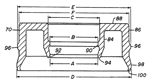
Seal ring 70 is best seen in FIGURES 3 and 4. The seal
ring 70 is an annular metal ring being U-shaped in section. It
includes an annular base portion 88, extending transversely to the
axes of the stem and bore, and from which inner leg 84 outer leg
86 extend axially in the same direction as shown, respectively
from the inner and outer peripheral portions of the base. The
outer leg 86 is longer than the inner leg 84 and both legs extend
axially away from the base 88 to distal ends. The diameters of
base portion 88 are such that it can be inserted within recess 44
and have a small clearance from the walls of the bonnet interior
and the stem exterior. As shown in FIGURE 3, diameter C will
always be greater than the outer diameter of stem 18 and diameter
F will always be less than the inner diameter of sealing surface
32 within bonnet 24.
Inner leg 84 has its interior cylindrical surface
extending axially away from the inner surface of base portion 88
to its approximate mid point where it extends inwardly to interior
cylindrical support surface 90 which is parallel to the axis.
Interior cylindrical support surface 90 is therefore connected to
the axially outer end of the interior cylindrical surface away
from the base. An arcuate interior concave surface extends and
curves outwardly and back inwardly from the outer portion of the
interior support surface away from the base 88. An interior
tapered surface extends radially inwardly and axially away from
;'i jJ .
,r,~ t,, "
g ~ r~ 65845-367
the base 88 from the outer portion of the arcuate interior sur-
face. An interior frusto-conical sealing surface 92, having a
diameter A slightly smaller than the diameter B of the interior
support surface of inner leg 84, extends from the axially outer
end of the interior tapered surface away from the base 88 and
ending in the distal end 94 of inner leg 84. Sealing surface 92
is at a slight angle to the axis of the seal ring as hereinafter
described.
The outer surface or exterior portion of inner leg 84
has a first exterior cylindrical surface extending from the base
88 axially to a point beyond support surface 90. The exterior
portion of inner leg 84 also has a tapered exterior surface
extending and tapering inwardly from the axially outer portion of
the first exterior cylindrical surface away from the base of the
inner leg from a point radially outward from the arcuate concave
interior surface of the leg to the distal end 94 of the leg.
Outer leg 86 has its outer or exterior cylindrical sur-
face extending axially away from the outer surface of base portion
88 to its approximate mid point. There, the outer axial end of
the exterior cylindrical surface away from the base 88 is connec-
ted to an exterior cylindrical support surface 96. The support
surface 96 is parallel to the axis of the seal ring. An exterior
arcuate recess extends from the outer portion of the exterior
support surface, first curving inwardly and then outwardly. A
first tapered exterior surface connects to said arcuate recess and
extends radially outwardly and axially away from the base 88. An
exterior frusto-conical sealing surface 98 connects to the axially
outer end of the first tapered exterior surface away from the base
~,....
10 ~ 65845-367
of said surface and has a diameter D slightly larger than the dia-
meter F of the exterior support surface. Sealing surface 98 is at
a slight angle outwardly to the axis of the seal ring as herein-
after described. A second exterior tapered surface extends from
the axially outer portion of the exterior sealing surface 98
radially inward and axially away from the base.
The outer leg 86 has an interior cylindrical surface
which extends axially from the base 88. A tapered interior sur-
face extends from the axial outer portion of the said interior
cylindrical surface away from the base and commencing at a point
radially inward of the start of the first exterior tapered sur-
face. The interior tapered surface tapers and extends radially
outward and axially away from the base to a position near distal
end 100 of outer leg 86. An arcuate interior surface extends from
the axially outer end of the interior tapered surface away from
the base and ends at distal end 100 of the outer leg 86, with the
surface extending generally radially inwardly and axially away
from the base. Separate surfaces 90 and 96 preferably are located
at the point of maximum deflection of their respective seal legs
84 and 86.
The seal ring 70 is adapted to be positioned between the
exterior stem surface 78 and the interior surface 76 of the bonnet
bore 32 with its inner and outer legs 84,86 extending in the
direction toward the source of pressure from the valves.
As shown in FIGURES 2, 3, and 4 diameter A of inner
sealing surface 92 is preferably less than the diameter of the
exterior of stem 18 and diameter D is preferably larger than the
diameter of sealing surface 76 on the interior of bonnet 24. Dia-
~,
~,
~ 2~ ~7l~ 65845-367
meter B, which is the diameter of support surface 90, is greater
than diameter A and also slightly greater than the diameter of the
exterior of stem 18. Diameter E, which is the diameter of support
surface 96, is less than diameter D and also is slightly less than
the diameter of sealing surface 76 on the interior of bonnet 24.
Diameter C, which is the diameter of the interior of base portion
88 and inner leg 84, is larger than the exterior of stem 18.
Diameter F, which is the diameter of the exterior of base portion
88 and of outer leg 86, is less than the diameter of the interior
of bonnet 24. Sealing surface 92 on inner leg 84 is tapered with
respect to the axis inwardly by the angle b and sealing surface 98
on outer leg 86 is tapered with respect to the axis outwardly by
the angle a. The radial difference between support surface 96 and
sealing surface 98 on outer leg is dimension d and the radial
difference between support surface 90 and sealing surface 92 is
dimension c, all as shown in FIGURE 4.
~,
: In the following chart suggested relationship of dimen-
sions for a 3 inch diameter stem which is positioned within a
:~ 3-3/4 inch diameter bore
.
A 2.992" B 2.999" C 3.042
D 3.762" E 3.755~' F 3.712
, ~ ~
a 1 35' b 1 35' c 0.0035"
~; d 0.035" e 15
Preferably, then, the frusto-conical sealing surface 98
of the outer leg 86 before installation tapers radially inwardly
and axially toward the annular base 88 at an angle a of approxi-
: mately one and one-half degrees. The frusto-conical sealing sur-
":~
. :~ face 92 on inner leg 84 before installation is preferably tapered
, ~ ~
: 7, L,
"'
. ,~'
,' ' ,
': :
:
12 1 ~ 2 ~ ~ ~7 l~ 65845-367
radially outwardly and axially toward the annular base at an angle
b of approximately one and one~half degrees. From the foregoing
it can be seen that the improved seal provides a positive metal-
to-metal seal against the exterior of the stem and the interior of
the bonnet bore which is designed so that each of the seal legs is
provided with a support surface so that even when they are exposed
to test pressures of substantial magnitude, such as 10,000 psi,
the pressure urging the legs against their sealing surfaces will
not cause permanent deformation of the legs.