Language selection

Search

Patent 1321631 Summary

Third-party information liability

Some of the information on this Web page has been provided by external sources. The Government of Canada is not responsible for the accuracy, reliability or currency of the information supplied by external sources. Users wishing to rely upon this information should consult directly with the source of the information. Content provided by external sources is not subject to official languages, privacy and accessibility requirements.

Claims and Abstract availability

Any discrepancies in the text and image of the Claims and Abstract are due to differing posting times. Text of the Claims and Abstract are posted:

  • At the time the application is open to public inspection;
  • At the time of issue of the patent (grant).
(12) Patent: (11) CA 1321631
(21) Application Number: 607407
(54) English Title: SURFACE MOUNT WIREWOUND RESISTOR AND METHOD OF MAKING THE SAME
(54) French Title: RESISTANCE BOBINEE A MONTAGE EN SURFACE ET PROCEDE DE FABRICATION
Status: Expired
Bibliographic Data
(52) Canadian Patent Classification (CPC):
  • 338/18
  • 338/25
(51) International Patent Classification (IPC):
  • H01C 1/034 (2006.01)
  • H01C 1/148 (2006.01)
  • H01C 3/00 (2006.01)
  • H01C 17/00 (2006.01)
(72) Inventors :
  • BOUGGER, GARY E. (United States of America)
(73) Owners :
  • VISHAY DALE ELECTRONICS, INC. (United States of America)
(71) Applicants :
(74) Agent: RIDOUT & MAYBEE LLP
(74) Associate agent:
(45) Issued: 1993-08-24
(22) Filed Date: 1989-08-02
Availability of licence: N/A
(25) Language of filing: English

Patent Cooperation Treaty (PCT): No

(30) Application Priority Data:
Application No. Country/Territory Date
236,718 United States of America 1988-08-26

Abstracts

English Abstract


ABSTRACT OF THE INVENTION
A surface mount wirewound resistor having a conventional
wirewound resistor embedded in a plastic body member with
terminal axial leads of the resistor being severed at the
opposite ends of the body member. A U-shaped metallic terminal
pad or clip is secured to the ends of the body member and is in
electrical contact with the severed ends of the axial leads.
The upper and lower portions of the terminal pad are in
coplanar relationship with the upper and lower surfaces of the
body member. An alternate surface mount wirewound resistor has
metallic tabs that extend from the resistance element embedded
in the plastic body member, with the tabs being bent upwardly
from the ends thereof and into coplanar relationship with the
upper surface of the body member. The method of making a
surface mount wirewound resistor entails embodying the resistor
having axial leads within a plastic body member, severing the
axial leads at the opposite ends of the body member, and then
placing terminal pads on the ends of the body member in contact
with the severed axial leads. An alternate method suspends the
resistor without axial leads between opposite sides of a
metallic lead frame by securing the end caps of the resistance
element to protruding terminal tabs. The resistance element is
then embedded in a plastic body member, the terminal tabs are
then severed from the lead frame and bent into coplanar
relationship with the upper surface of the body member.


Claims

Note: Claims are shown in the official language in which they were submitted.


The embodiments of the invention in which an exclusive property
or privilege is claimed are defined as follows:
1.
A surface mount resistor, comprising,
a substantially hard plastic rectangularly-shaped body member
having substantially flat and parallel upper and lower
surfaces, opposite sides, and opposite ends,
an electrical resistance element embedded in said body member and
having a pair of spaced terminal ends which extend through
said body member and terminate substantially at the exterior
surface of said body member,
and a pair of spaced electrical terminal pads secured to the
exterior surface of said body member with one each of said
terminal pads being in electrical contact with said one each

of said terminal ends.
2.

The resistor of claim 1 wherein said spaced terminal ends
communicate with the exterior surface of said body member at the
opposite ends thereof.
3.
The resistor of claim 2 wherein said terminal pads are U-
shaped metallic clips that receive the opposite ends of said body
member.
4.

The resistor of claim 2 wherein said terminal pads are U-
shaped metallic clips that receive the opposite ends of said body
member and have exposed electrical contact portions adjacent a
portion of the upper or lower surfaces of said body member.

-9-

5.
The resistor of claim 2 wherein said terminal pads are U-
shaped metallic clips that receive the opposite ends of said body
member and have exposed electrical contact portions adjacent a
portion of the upper and lower surfaces of said body member.
6.
The resistor of claim 2 wherein metallic clips have a bight
portion that engages the ends of said body member, and upper and
lower legs that engage a portion of the upper and lower surface,
respectively, of said body member adjacent the ends of said body
portion.
7.
The resistor of claim 6 wherein said body portion is recessed
to receive said upper and lower legs of said metallic clips, the
upper and lower surfaces of said body member having center por-
tions, respectively, said upper and lower legs having an exposed
flat electrical contact surface that dwells in the same plane as
said center portions.
8.
The resistor of claim 1 wherein said resistance element
comprises a core, a pair of terminal caps on said core and con-
nected to said terminal ends, and an electrical resistance wire
wound on said core and connected to each of said terminal caps.
9.
The resistor of claim 1 wherein said terminal ends are
elongated round members which have their ends secured within
apertures within said terminal pads.

-10-

10.
A surface mount resistor, comprising,
a substantially hard plastic rectangularly-shaped body member
having substantially flat and parallel upper and lower sur-
faces, opposite sides, and opposite ends,
an elongated resistance element embedded in said body member and
having a pair of terminal ends,
lead tabs secured to said terminal ends and extending outwardly
of said body member,
said lead tabs being in coplanar engagement with said upper
surface of said body member.
11.
The resistor of claim 10 wherein said lead tabs exit said
opposite ends of said body member, with said lead tabs being bent
into said coplanar engagement with said upper surface of said
body member.
12.
The method of making a surface mount resistor, comprising,
taking an elongated resistance element comprising a core, a pair
of terminal caps on the ends of said core, and a resistance
wire wound on said core and electrically connected to said
terminal caps, with elongated straight axial leads secured to
said terminal caps and extending outwardly in alignment with
the longitudinal axis of said core,
embedding said resistance element in a rectangular plastic body
member having substantially flat and parallel upper and lower
surfaces, and opposite ends with said axial leads extending
from said opposite ends,

-11-

severing said axial leads at a point adjacent said opposite ends,
and securing electrical terminal pads to said body member in
electrical contact with said severed axial leads.
13.
The method of claim 12 wherein said terminal pads are
extended from the opposite ends of said body member to engage at
least one of the upper or lower surfaces of said body member.
14.
The method of making a surface mount resistor, comprising,
taking an elongated resistance element comprising a core, a
pair of terminal caps on the ends of said core, and a
resistance wire wound on said core and electrically
connected to said terminal caps, with elongated straight
axial leads secured to said terminal caps and extending
outwardly in alignment with the longitudinal axis of said
core,
embedding said resistance element in a rectangular plastic body
member having substantially flat and parallel upper and lower
surfaces, and opposite ends with said axial leads extending
from said opposite ends,
and bending said axial leads into coplanar engagement with said
upper surface of said body member.
15.
The method of claim 14 wherein axial leads are metal tabs
extending from opposite sides of a metal lead frame, and said
metal tabs are severed from said lead frame after said resistance
element is embedded in said plastic body.

-12-

16.
The method of making a surface mount resistor, comprising,
taking an elongated resistance element comprising a core, a pair
of terminal caps on the ends of said core, and a resistance
wire wound on said core and electrically connected to said
terminal caps,
taking a rectangular-shaped metal lead frame including opposite
sides having electrical lead tabs extending inwardly towards
the center of said frame,
connecting said terminal caps to one each of said lead tabs,
embedding said resistance element in a rectangular plastic body
member having substantially flat and parallel upper and lower
surfaces, and opposite ends with said lead tabs extending
from said opposite ends,
severing said lead tabs from said lead frame,
and bending said lead tabs into coplanar engagement with said
upper surface of said body member.

-13-
Description

Note: Descriptions are shown in the official language in which they were submitted.


1~2~31

~CKGROUND OF THE I~VE~TION
mhe present technology for wirewound resistors consists Oc
a cylindrical ceramic core to which metal end caps are attached
on each end. wire terminals are then attached to t~e metal end
caps. Resistance wire is wound around the ceramic core and
affixed in some manner to the metal end caps. This unit is
then encapsulated using various techniques and encapsulating
materials to provide protection to the resistance wire from
various environments to which they may be exposed. This is a
proven design as evidenced by the excellent reliability these
resistors have demonstrated for millions of users in a wide
varie~y o~ applications. They are ~nown for their high
reliability; eY.cellent resistance stability, with low
temperature coefficient; and their ability to dissipate large
amounts of power utilizing a small package size when compared
to other resis.or technologies.
A major drawback to this design in today's state of high
automation is tha' this design requires considerable expense by
the end customer to install the resistor into a circuit boar~.
The circuit board must have holes placed in it which are
suitable in size to accept the resistor terminals. The
res~stor terminals must then be cut to the proper lensth and
~ormed in some manner so the terminals may be inserted into the
holes in the circuit board. The terminals are then permanently
attached to the circuit board using any number of circuit board
soldering technigues such as infrared reflow or wave solaering.
Circuit board designers utilizing this technology are limited
to mounting components on only one side of the circuit board as
the resistor terminals protrude through the circuit board.
It is, the_efore, a principal object of this invention to
proviae a surface mount resistor which can be mounted to
~..


1321631
terminals on a circuit board without creating holes in the
circuit ~oard or without cutting the resistor terminals.
It is a further object of this invention to provide a
surface mount resistor which can be mounted on either or both
sides of the circuit board.
A still further object of the invention is to provide a
surface mount resistor which will require less space on the
circuit board since the terminals are an integral part of the
surface mount component.
A still further object of the invention is to provide a
surface mount resistor which is compatible with automated
circuit board manufacturing e~uipment and techniques, and which
can be economically manufactured.
A still further object of this invention is to provide a
method of manufacturing a surface mount wirewound resistor
which is economical and efficient from a manufacturing
standpoint.
These and other objects will be apparent to those skilled
in the art.

SUMMARY 0~ TX~ INVE~ION
~ The invention provides a conventional wirewound resistor
(or alternately, a metal film resistor) embedded in a plastic
body member with ~he conventional te_minal axial leads o' the
resistor being severed at the opposite ends of the body member.
A U~shaped metzllic terminal pad or clip is secured to the ends
of the body member and is in electrical contact with the
severed ends o~ the axial leads. The upper and lower portions
of the terminal pad are in coplanar or flush relationship with
the upper and lower surfaces of the body member.


An alternate form of the invention utilizes metallic tabs
that extend from the resistance element embedded in the plastic
body member, with the tabs being ben~ upwardly from the ends
thereof and into coplanar relationship with the upper surface
of the bo~y member.
T~e method of making the surface mount wirewound resistor
~f this invention entails embodying the wirewound resistor in
a plastic body member, severing the axial leads of the resistor
at the opposite ends of the body member, and then placing
U-shaped terminal pads or clips on the ends of the body member
in electrical engagement with the severed axial leads.
An alternate method of making the surface mount wirewound
resistors of this invention is to eliminate the conventional
axial leads of the wirewound resistor and suspend the resistor
between opposite sides of a metallic lead frame by securing the
end caps of the resistor to protruding terminal tabs which
extend inwardly from the opposite sides of the lead frame. The
resistance element is then embedded in a rectangular plastic
body member. The terminal tabs are then severed from the lead
frame, and the terminzl tabs are bent into a coplanar
rel~ationship with the upper sur_ace of the body member.

BRIEF DESCRIPTION OF TT.~ D~AWINGS
Fig. 1 is a side elevational view oS a conventional
wirewound resistor;
Fig. 2 is an elevational view similar to that of Fig. 1
but shows a coating material over the wirewound resistor;
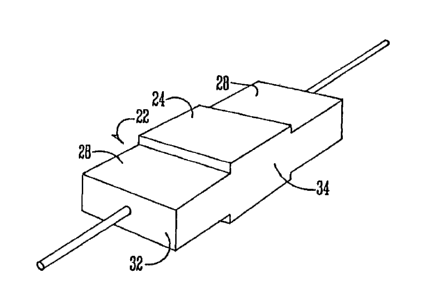
Fig. 3 is a perspective view at a reduced scale of the
resistor of Fig. 2 embedded in a rectangular plastic body
member;

1~21~3~

Fig. 4 is a side elevational view of the body member of
Fig. 3 with one ~f the aY.ial lead members shown in the process
of being severed;
Fig. 5 is a perspective view of a metallic terminal pad or
clip to be mounted on the ends of the body member of Figs. 3
and 4;
Fig. 6 is a perspective view of the body member of Fig. 3
with the terminal pads of Fig. 5 mounted on opposite ends
thereof;
Fig. 7 is a longitudinal sectional view of the body member
of Fig. 6 ta~en on line 7-7 of Fig. 6;
Fig. 8 is an elevational view of a conventional resistor
similar to that of Fig. 1 but with the axial leads removed
therefrom;
Fig. 9 is an elevational view of a conventional resistor
similar to that of Fig. 2 but also with the terminal leads
eliminated therefrom;
Fig. 10 is a perspective view at a reduced scale of a lead
frame used to support the conventional resistor of Fig. 9
during the molding process;
~ Fig. ll is a plan view of the lead frame of Fig. 10 with a
plurality of resistors of Fig. 9 mounted in supporting
condi.ion the~eon;
Fig. 12 is a plan view similar to tha. of Fig. 11 but
shows the resistors of Fig. 11 after they are embedded in a
rectangular plastic body member;
Fig. 13 is a perspective view shown at an enlarged scale
of the body members and resistors removed from the lead frame
of Fig. 12;


1~21631

Fig. 14 is a side elevational v~ew of the resistor o. ~ic.
13 zfter the terminal ta~s have been ~ent into their p.eferred
position.

DESCRIPTION OF THE PREFERRED EM9ODIME~'T
A conventional wirewound resistor element 10 is shown in
Fig. 1 and comprises a cylindrical ceramic core 12 with metal
end caps 14 mounted on opposite ends thereof. Metal aY~ial
leads 16 are secured to caps 14 and eY.tend outwardly therefrom
in alignment with a longitudinal axis of core 12. A resistance
wire 18 is wound on core 12 and has the ends thereof
electriczlly connected to the end caps 14. Fig. 2 shows the
device of Fig. 1 with a high temperature silicone coating 20
sprayed or otherwise placed thereon. The structure of Figs. 1
and 2 is conventional in the art and does not, per se,
constitute the essence of this invention.
With reference to ~igs. 3 and 4, the resistor element 10
of Fig. 2 is embedded by conventional means in a high
temperzture silicone (or epoxy) rectangular body member 22.
This embedding ?rocess is ~nown in the elect~iczl zrt znd is
cre~ted in z molding process wherein the resistor 10 i5
surrounded in a mold by a liauid high temperzture silicone
mzterizl created by subjecting the silicone grznules to hish
conditions of hezt znd pressure. The shape and configurztion
of the body member 22 is believed to be novel. Body member 22
hzs an upper surface 24 and a lower surface 26, both of which
comprise the center portions of the body member. 30dy member
22 also includes upper recess surfaces 28 and lower recess
surfaces 30, ends 32, and sides 34.
A metallic terminzl pad 36 is shown in ~ig. 5 and is
comprised of a U-shaped clip having a bight portion 38 which

-6-


~32~631

integrally e~tends into horizontal upper and lower legs 40 and
~2, respective7y. ~fter the body member 22 is formed, the
axial leads 16 are severed as shown at the right-hand end of
Fig. 4 to create a lead segment 44 that is received in
aperture 46 in t~e bight portion 38 of terminal pad 36. The
terminal pads 36 are attached to the ends of the body mem~er 22
by means of soldering, welding, or swaging to ensure electrical
continuity. The terminal pads 22 may be covered wit~ a
tin-lead solder material (not shown) to ensure easy soldering
by the end user.
~ n alte_nate form of the inven~ion is shown in Figs. 8
through 13. ~ conventional resistor element lOA is shown in
Fig. 8, and it is identical to the resistor element 10 shown in
Fig. 1, except that the axial leads 16 of Fig. l have been
eliminated in the device of Fig. 8. Fig. 9 merely shows the
high temperzture silicone coating 20 added to the structure of
Fig. 8.
A lead frame 50 is shown in Fig. 10 and is preferably
stzmped in any desirable length from an elongated sheet of thin
copper material. Frame 50 is comprised of sides 52, ends 54,
and~cross-members 56 which divide the frame into a plurality of
open spzces 58. ~ny desired number of open spaces 58 may be
created by varying the len,h of frame 50. Lead tabs 60
integrzlly ormed with sides 52 extend inwardly towards the
centers of each open space 58. Alignment holes 62 are formed
in sides 52 to facilitate the molding process which will be
described herea~ter.
The resistors lOA shown in ~ig. 9 are welded or otherwise
secured between opposite lead tabs 60. The lead frame is then
placed in a conventional plastic mold znd a rectangular body
member 22A comprised of high temperature silicone is created by

1321 6~

the same molding technique described in re~ard to body member
22. The body member 22A is essentially iden.ical tO the
previously described body member 22 except that the recesses 28
and 30 of body member 22 are eliminated and recesses 64 in the
upper surface 24 are utili~ed in lieu thereof.
After the molding of body member 22A has been completed,
the lead tabs 60 are severed from the lead frame 50 so that a
substantial length of the lead tabs 60 protrude from the ends
of body member 22A. These protruding lead tabs 60 are then
bent upwardly and thence horizontally into the recesses 64 as
best shown in Fig. 14. Again, the lead tabs 60 can be coated
with a tin-lead solder (not shown) to ensure easy soldering by
the user.
The rectangular configuration of the body members 22 and
22A helps ensure that the resistor will not have a tendency to
tip or move once the resistor is placed on the circuit board.
This avoids the problem of cylindrical shaped resistors which
are less stable when placed on the circuit board and which
often will tip or roll off the board during installation. This
occurrence necessitates a rework operation to correctly
rep~sition the resistor on the circuit board. The terminal
configuration of the embodiment o~ Figs. 8-14, through the
laterally wide lead tabs 60 ensures a sufficient solder
connection when the resistor is soldered to the circuit board.
The wide lead tabs 60 are capable of handling high electrical
current which is required with resistance values below 1.0
ohms.
From the foregoing, it is seen that this invention
achieves at lezst 211 of its stated objectives.

Representative Drawing
A single figure which represents the drawing illustrating the invention.
Administrative Status

For a clearer understanding of the status of the application/patent presented on this page, the site Disclaimer , as well as the definitions for Patent , Administrative Status , Maintenance Fee  and Payment History  should be consulted.

Administrative Status

Title Date
Forecasted Issue Date 1993-08-24
(22) Filed 1989-08-02
(45) Issued 1993-08-24
Expired 2010-08-24

Abandonment History

There is no abandonment history.

Payment History

Fee Type Anniversary Year Due Date Amount Paid Paid Date
Application Fee $0.00 1989-08-02
Registration of a document - section 124 $0.00 1989-11-16
Maintenance Fee - Patent - Old Act 2 1995-08-24 $100.00 1995-07-20
Maintenance Fee - Patent - Old Act 3 1996-08-26 $100.00 1996-07-18
Maintenance Fee - Patent - Old Act 4 1997-08-25 $100.00 1997-07-16
Maintenance Fee - Patent - Old Act 5 1998-08-24 $150.00 1998-07-17
Maintenance Fee - Patent - Old Act 6 1999-08-24 $150.00 1999-08-05
Maintenance Fee - Patent - Old Act 7 2000-08-24 $150.00 2000-07-26
Registration of a document - section 124 $50.00 2000-12-01
Maintenance Fee - Patent - Old Act 8 2001-08-24 $150.00 2001-07-30
Maintenance Fee - Patent - Old Act 9 2002-08-26 $150.00 2002-07-18
Maintenance Fee - Patent - Old Act 10 2003-08-25 $200.00 2003-07-23
Maintenance Fee - Patent - Old Act 11 2004-08-24 $250.00 2004-07-19
Maintenance Fee - Patent - Old Act 12 2005-08-24 $250.00 2005-07-08
Maintenance Fee - Patent - Old Act 13 2006-08-24 $250.00 2006-07-05
Maintenance Fee - Patent - Old Act 14 2007-08-24 $250.00 2007-07-30
Maintenance Fee - Patent - Old Act 15 2008-08-25 $450.00 2008-07-10
Maintenance Fee - Patent - Old Act 16 2009-08-24 $650.00 2009-10-14
Owners on Record

Note: Records showing the ownership history in alphabetical order.

Current Owners on Record
VISHAY DALE ELECTRONICS, INC.
Past Owners on Record
BOUGGER, GARY E.
DALE ELECTRONICS, INC.
Past Owners that do not appear in the "Owners on Record" listing will appear in other documentation within the application.
Documents

To view selected files, please enter reCAPTCHA code :


To view images, click a link in the Document Description column. To download the documents, select one or more checkboxes in the first column and then click the "Download Selected in PDF format (Zip Archive)" or the "Download Selected as Single PDF" button.

List of published and non-published patent-specific documents on the CPD .

If you have any difficulty accessing content, you can call the Client Service Centre at 1-866-997-1936 or send them an e-mail at CIPO Client Service Centre.


Document
Description 
Date
(yyyy-mm-dd) 
Number of pages   Size of Image (KB) 
Representative Drawing 2001-11-26 1 6
Drawings 1994-03-04 3 63
Claims 1994-03-04 5 145
Abstract 1994-03-04 1 38
Cover Page 1994-03-04 1 16
Description 1994-03-04 7 271
Examiner Requisition 1992-07-20 1 47
PCT Correspondence 1993-05-28 1 23
Prosecution Correspondence 1992-10-28 1 34
Fees 1996-07-18 1 76
Fees 1995-07-20 1 74