Note: Descriptions are shown in the official language in which they were submitted.
`` 1321830
A NETHOD AND APPARATUS FOR INDEPENDENTLlr TRaNS~ITTING
AND REQPTURING CLOCR RECOVERY BIJRST AND DC RESTORATION
SIGNALS IN A I~AC SYSlq~N
B~CRGROllND OF '1'~ INV~TION
Technical Field
The present invention is directed ~o improving
immunity to channel distortions of multiplexed analog
component television signals by independently
transmitting a clock recovery signal and a DC
restorati~n signal during the horizontal blanking
interval of a video line. More particularly, the clock
recovery signal and the DC restoration signal are
transmitted on independent lines.
Background Infsrmation
BRIEF DESCRIPTION OF THF DRAWINGS
As reference now will have to be made to the
drawings, they will first be described briefly as
follows:
Figure 1 is an amplitude --vs.-- time diagram of a
single video line of a MAC signal.
Figure 2 illustrates a line of a MAC video signal.
Figure 3 illustrates a detailed view of the
horizontal blanking interval of the line shown in
Figure 2.
Figure 4 illustrates the block diagram of the
circuitry required to recover the clock recovery signal
and the DC restoration signal transmitted during the
horizontal blanking interval of Figure 2.
Time division multiplexed analog component (MAC)
television signals, a typical line of which is shown
with reference of Figure 1, includes a horizontal
blanking interval (HBI) 12, in which no picture
information is transmitted, followed by a chrominance
signal 14 and a luminance signal 16, either of which may
be time-compressed. Between the chrominance and
la ~3 2 ~83 n
luminance signals is a guard band 18 to assist in
preventing interference between the two signals.
The MAC color television signal of Figure 1 is
obtained by generating conventional luminance and
chrominance signals (as would be done to obtain a
conventional NTSC or other composite color television
signals) and then sampling and storing them separately.
Luminance is sampled at a luminance sampling frequency
and stored in a luminance store~ while chrominance is
sampled at a chrominance sampling frequency and stored
in a chrominance store. The luminance or chrominance
samples may then be compressed in time by writing them
into a store at their individual sampling frequency and
reading them from
. . . . ~ ~
1321830
the store at a higher frequency. A multiplexer selects either the luminance
store or the chrominance store, at the appropriate time during the active line
period, for reading, thus creating the MAC signal. If desired, audio samples maybe transmitted during the HBI; these are multiplexed (and may be compressed) in
the same manner as the video samples. The sample rate at which all samples
occur in the multiplexed MAC signal is called the MAC sampling frequency.
In the transmission of all typical MAC signals, a reference clock fre-
quency burst is also transmitted during the HBI. The reference burst is typically
about ten cycles of a constant amplitude sinusoid at the MAC sampling fre-
quency and is used at the receiver for both clock recovery and DC restoration
(clamping). The frequency of the reference clock burst is used for clock
recovery, while the average of the reference clock burst (ideally zero) is used for
clamping. It is of great importance to accurately DC restore the video signal
after transmission and clamp on the luminance (or pedestal~ value upon which
these reference clock burst sinusoids are superimposed. The chrominance values
obtained for transmission are relative to a given reference brightness level, rep-
resented by the DC level of the signal. Accordingly, it is necessary that thP
received signal be referred to that reference level to provide accurate recon-
struction of the received signal on a display. This reference level is hereinafter
referred to æ the DC restoration value.
Several problems exist with the prior art method of obtaining the DC res-
toration value by averaging the reference clock burst. For example, if the
discriminator at the receiver (Foster Sealy or FM discriminator) is misaligned,
the average value of the reference clock burst is not at its ideal zero reference
point. Additionally, if a large data spike either before or after the reference
clock burst occurs, when low pass filter the clock burst, the data spike will cause
interference and shift the DC level. Furthermore, any other distortion classi-
cally inherent in FM discriminators will cause an error to occur when the DC
restoration value is obtained by averaging the reference clock burst.
. - . . , :
. . , ;, :
., .. ,., . ~,
1321830
This error, sometimes referred to as chrominance/luminance intermodulation,
is a non-linear distortion particularly likely to be encountered in FM discriminators
as a result of misalignment or drift. It may also occur in a wide variety of baseband
video amplifiers, especially as a result of differences in circuit component value
5 tolerances. A test signal has been developed specifically to measure this distortion in
an FM demodulator. See Int?l Radio Consultative Comm., Recommendations And
Reports Of The CCIR, Transmission of Sound Broadcasting and Television Signals
Over Long Distances, Vol. XII, pps. 13, 20 (XVth Plkenary Assembly, Geneva 19~2).
One solution to this problem is to provide a separate clock recovery signal
10 and DC restoration signal in each transmitted line. If the reference clock burst and
the DC restoration signal were both about 3 us per line, these two intervals would
represent approximately 10% of the typical 63.5 us line. This approach is
uneconomical; not only will the bandwidth required for transmission be increased,
but the signal-to-noise ratio would also be increased, requiring a larger antenna "
reflector and/or a more costly Low Noise Amplifier.
Summarv of the Invention
The problems inherent with trying to obtain the DC restoration value from
the reference burst lie from the fact that the two values are not related, as well as
from the distortions classically inherent in FM discriminators. Accordingly, it is an
object of an aspect of the present invention to transmit the clock recovery signal and
the DC restoration signal independently of each other.
It is an object of an aspect of the present invention to transmit these values
on separate lines.
Various aspects of the invention are as follows:
In a frequency modulated time division multiplexed analog component video
signal having a line which includes a luminance component, a chrominance
component and a horizontal blanking interval which comprises either a clock recovery
burst or a DC restoration level, but not both, the method of transmitting multiple
lines of the video signal characterized by the steps of:
3 o transmitting a first line of the video signal wherein the horizontal
blanking interval comprises the clock recovery burst; and
transmitting N subsequent lines of the same video signal wherein
a) N is an integer equal to any number less than the
number of lines per field in the video system, and
' ' ~ ': ~ ' . : '
132~ ~3!~
3a
b) the horizontal blanking interval comprises the DC
restoration reference level.
In a frequency modulated time divis:ion multiplexed analog component video
signal having a line which includes a luminance component, a chrominance
5 component and a horizontal blanking interv,al which comprises either a clock recovery
burst or a DC restoration level, but not both, a transmitter for transmitting multiple
lines of the video signal characterized by:
means for transmitting a first line of the video signal wherein the
horizontal blanking interval comprises the clock recovery burst; and
means for transmitting N subsequent lines of the same video signal
wherein
a) N is an integer equal to any number less than the
number of lines per field in the video system, and
b) the horizontal blanking interval comprises the DC
15 restoration reference level.
In a video signal receiver for receiving multiple lines of a time division
multiplexed analog component video signal having either a clock recovery burst or a
,` DC restoration reference level transmitted during a predetermined portion of each
]ine's horizontal blanking interval, a device for recapturing the clock recovery burst
20 and the DC restoration reference level characterized by:
. first pulse generating means for generating a first enable pulse whose
timing and duration correspond substantially to the predetermined portion of each
line's horizontal blanking interval;
second pulse generating means having first and second output ports for
25 generating a second enable pulse having a duration corresponding to the transmitted
line time and alternately outputting said second enabled pulse at said first and second
output ports after every N line time durations;
first coincidence gate coupled to said first pulse generating means and the
first output port of said second pulse generating means to output a first gating signal
30 during the coincidence of said first enable signal and said second enable signal at the
first output port;
first gating means coupled to said first coincidence gate for receiving the
transmitted video lines and outputting a portion of the video line corresponding to
said first gating signal;
.,
.~
.- ., ,; - ~ : :
- 132183~
3b
second coincidence gate coupled to said first pulse generating means and the
second output port of said second pulse generating means to output a second gating
signal during the coincidence of said first enable signal and said second enable signal
at the second output port;
second gating means coupled to said second coincidence gate for outputting a
reference level value signal corresponding to the duration of said second gating
signal. y
In a video signal receiver for receiving multiple lines of a time division
multiplexed analog component video signal having either a clock recovery burst or a
10 DC restoration reference level transmitted during a predetermined portion of each
line's horizontal blanking interval, a method for recapturing the clock recovery burst
and the DC restoration reference level comprising:
receiving a first line of said time division multiplexed analog
component video signal having a clock recovery burst and carrying out a dock
15 recovery operation, but not a DC restoration operation; and
receiving N subsequent lines of said tirne division multiplexed analog
component video signal having a DC restoration reference level and carrying out a
DC restoration operation, but not a clock recovery operation.
~i; $
,.
.. , . ~.
.
,
.. . .
1321~0
According to the objects of the present invention,
I have found that the integrity of the television
receiver's system is not compromised if the clock
recovery signal is not transmitted on avery line. In
fact, a substantial major~ty of the transmitted lines
per frame need not have the clock recovery signal
present for proper operation. Accordingly, the problems
inherent in the prior art ar~ avoided by independently
transmitting the clock recovery signal and the DC
restoration signal on separate lines during a portion of
the horizontal blanking interval of the respective
lines. The clock recovery signal and the DC restoration
signal could be transmitted on alternate lines or the
clock recovery signal could be sent every Nth line with
the DC restoration signal transmitted on lines
~herebetween.
DESCRIPTION OF ~HE PREE'ERRED EMBODIID~TS
With reference to Figures 2 through 4, the
transmission and recovery of the clock recovery signal
and DC the restoration signal will not be described. As
shown in Figura 2, a line of a MAC video signal
comprises a time segment for horizontal blanking
interval (HBI) 21, chrominance component 22, guard band
23 and luminance component 24. Turning now to Figure 3,
a detailed view of the horizontal blanking interval of
the line shown in Figure 2 is now described with
reference to the multiplexed analog component
transmission system developed by the assignees of the
present invention, typically referred to as B-MAC. As
shown in Figure 3, the horizontal blanking interval
comprises data segments 31, 32 and 33, separated by
guard bands 34 and 35. In the preferred embodiment, the
HBI comprises 78 symbols divided as 47 4-level data
symbols for data segment 31;
132183Q
20 4-level data symbols for data segment 32; 7 4-level data symbols for data seg-
ment 33; and 2 symbols for each guard band 34 and 35. Data segment 32 is used
to store either the clock recovery signal or the DC restoration signal, depending
upon the transmitted line in question. During transmission of the clock recoverysignal, data segment 32, which is preferably approximately 2 us in duration,
comprises a series of alternating minima and maxima Qf the 4-level data values
and represents a clock recovery signal having constant amplitude and a fre-
quency of the MAC sampling frequency. During the transmission of the DC res-
toration signal, data segment 32 preferably comprises twenty symbols of data at
50 IRE (i.e., the exact center of the dynamic range). Data segments 31 and 33
include other data, such as audio and/or scrambling information, a description of
which is both known in the art and not necessary for a full understanding of thepresent invention.
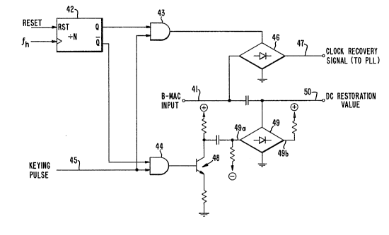
Turning now to Figure 4, the block diagram of the circuitry at the
receiver required to recovery the clock recovery signal and the DC restoration
signal which was transmitted during the horizontal blanking interval as just
described is now discussed.
in the preferred embodiment, the clock recovery signal is transmitted on
every other line, and the received B-MAC signal is input at line 41. Divide-by-Ncounter 42 is preferably a divide-by-2 counter and is reset according to the field
rate reset pulse and is clocked by the line frequency fh. The outputs of counter42 are arranged such that AND gates 43 and 44 are enabled mutually exclusive of
each other by tying one of the two inputs to Q and Q-bar, respectively. The
other input to AND gates 43 and 44 is the keying pulse of line 45 which occurs
during data segment 32 (of Figure 3) of the horizontal blanking interval and has a
duration of the twenty symbol data segment, preferably about 2 us. The keying
pulses are generated by a key pulse generator (not shown), the construction of
which will be obvious to those skilled in the art. When a first line is received at
~21830
input 41, and assuming that the first line contains a clock recovery signal as
described above, AND gate 43 is enabled and the clock recovery signal is allowedto pass through transmission gate 46 to the phase-locked loop circuitry (not
shown) connected to line 47. During alternately occuring lines, AND gate 44 is
enabled, thereby turning on transistor 48 and allowing the 50 IRE signal, pro-
duced by input sides 49a and 49b of transmission gate 49 to pass through the sys-
tem at line 50. It is to be noted that the minima and maxima voltage values cou-pled to points 49a and 49b, respectively, represent the minima and maxima of
the four-way data contained in the transmitted line of Figure 2.
Although the preferred embodiment has been described with reference to
transmitting the clock recovery signal and the DC restoration signal on alternate
lines, it is also possible to transmit the clock recovery signal on every third line,
with the DC restoration signal transmitted on lines therebetween. In an embodi-
ment of this type, divide-by-N counter 42 would be replaced with a divide-by-
three counter, and the reset pulse into the counter would become the frame rate
reset pulse (i.e., reset on line l of each field).
It is still further possible to transmit the clock recovery signal on every
Nth line with the reset pulse into clock counter 42 preferably being the frame
rate reset pulse provided that the number (N+l) is an integer multiple of the
number of lines per frame. Additionally, it is also possible to transmit the DC
restoration signal every Nth line, with the clock recovery signal transmitted onlines therebetween.
Although illustrative embodiments of the present invention have been
described in detail with reference to the accompanying drawings, it is to be
understood that the invention is not limited to those precise embodiments. Vari-ous changes or modlfications may be effected therein by one skilled in the art
without departing from the scope or spirit of the invention.