Note: Descriptions are shown in the official language in which they were submitted.
1321913
Suspension system for a flexible optical membrane
Technical Field
This invention relates to a suspension system for
holding under tension a flexible membrane employed as
a boundary surface of a liquid lens of adjustable focus
or a flexible membrane mirror and to a new design of
liquid lens, the focal length of which can be altered
by relative movement between component parts of the lens
holder. The invention also relates to an adjustable
focus mirror.
A liquid lens consists of at least one flexible
transparent membrane which defines a boundary surface
of a space that can be filled with a liquid. The liquid
can be at a higher or lower pressure than the medium
(usuall~ air) contacting the other side of the membrane,
the pressure difference across the membrane causing it
to curve so tha~ the liquid-filled space functions a~
a lens.
A membrane mirror consists of a flexible membrane
suspended in a frame of circular or other shape and with
a reflective coating on one or both sides. Pressure
applied to the membrane causes it to assume an appropriate
-~ conformation and allow the reflective coating to func-
tion as a mirror.
For each device, the membrane requires to be appro-
' priately supported while the required shape-deforming
pressure is applied to it. The present invention provides
-a method of supporting a membrane, forming part of a
` liquid lens or flexible mirror, under tension and thus
provides improved liquid lenses and mirrors.
:. ~
.-
~: .
: ,-~ ,: ~ : -
.-: . . ,
,
132i913
Summary of the Invention
According to one aspect of this invention, the boun-
dary surface of a liquid lens or flexible mirror is de-
fined by a flexible membrane supported between two resil-
ient O-rings supported opposite one another in a frame
with the membrane placed between the two O-rings, and
in that pressure is applied to the O-rings via the frame
to cause the line of contact each O-ring makes ~ith the
membrane to become an annular zone producing an outwardly
directed radial tension at all points in the membrane,
thereby holding it in the frame under tension.
Conveniently the resilient rings are identical rings
of elastomeric material of circular cross-section (known
as O-rings) but identical rings of elastomeric material
of non-circular cross-section can also be used.
It is also possible to use rings of different cross-
sections on the opposite sides of the membrane and even
rings of somewhat differen~ diameters, provided confront-
ing zones are produced around the boundary surface.
In place of solid O-rings, hollow O-rings can be
used. The pressure in a hollow O-ring can be varied
to modify the radial tensions induced by it. Hollow
~-rings can be divided into t~o or more sealed sections
of the same or different lengths whereby the properties
of each section can be altered by gas or liguid pumped
into them. By varying the pressure in different sections,
unequal radial tensions can be induced in the supported
membrane. This allows controllable compensation for
unequal forces acting on the membrane, such as centrifugal
forces (if the boundary surface is part of a rotating
system) or gravitationa~ forces.
The resilient ring may be held in its supporting
frame but not attached to it. However, the ring may
be bonded t~ a supporting frame or even be an integral
part of it. Thus, for example a moulded frame of plastics
~, . .
.~ .. .
.
,, ~ "
, .
1321913
material may have an extrusion with a semi-circular cross-
section or a cross-section of some other appropriate
shape extending ~rom the frame in a position in which
the resilient ring is required~ To ensure adequate resil-
ience, the extruded ring`may be hollow.
Two identical resilient rings can be supported oppo-
site one another in a frame and the membrane placed
between the two rings. Pressure can be applied to the
rings via the frame to cause the line of contact each
ring makes with the membrane to become an annular zone
producing an outwardly directed radial tension at all
points in the membrane, and thus holding it in a flat
condition under tension.
- The compression forces applied at different parts
of the circumference of the annular frame can be varied.
This will cause different radial tensions in different
parts of the membrane and allow controllable compensation
~ for unequal forces which might be acting on the membrane
-(such as the centrifugal or gravitational forces mentioned
above).
The force on the supported membrane at any point
where the rings contact it, is determined by the ~compres-
sion forces acting on the resilient rings and the diameter
and cross-sectional shape of the rings. The local force
on the resilient rings may be altered by changing any
of these parameters.
According to a further aspect of the invention an
adjustable liquid lens or mirror comprises a chamber
delimited by a flexible membrane surface, a first fluid
,, ~ , .: . . . . .............................................. .
~,, .
~ . .
1321913
-- 4
medium filling the chamber which, in the case of a lens,
has a different refractive index from that of a second
fluid medium contacting the other side of the flexible
membrane, and an annular support member for the flexible
membrane comprising relatively movable first and second
component parts; the first and second c~omponent parts
of the support member exhibiting closely adjacent matching
surfaces (eg cylindrical) between which an O-ring seal
is located and being adjustably linked in a fluid-
io tight manner whereby the volume of the chamber is adjust-
able by moving one component part of the support member
relative to the other in such wise as to vary the pressure
in the first fluid medium and thereby to alter the shape
of the said membrane surface, the membrane defining said
membrane surface being held in place between a compressed
pair of O-rings.
~ The lens or mirror desirably has the component parts
of the support member screw-threaded together so that
relative rotation of one in or on the other c~uses the
required pressure change in the first fluid medium.
- Alternatively, one component part may fit into the other
so that by sliding it in or out (by use of a ratchet
or other means) the pressure may be altered accordingly.
i.
.~ :
:
1321913
-- 5
_ ief Description of the Drawings
The invention will now be further described, by
way of example, with reference to the accompanying draw-
ings, in which:
Figure 1 shows, in schematic cross-section, a first
embodiment of liquid lens in accordance with this inven-
tion,
Figure 2 shows, in cross-section, an alternative
form of resilient ring for supporting a membrane in the
lens of Figure 1,
Figure 3 illustrates the mode of operation of the
resilient rings in supporting the membrane,
Figure 4 is a purely s-chematic sectional side ele-
vh':ion of a second embodiment of liquid lens according
to the invention,
Figure S is a view similar to Figure 4 but of a
two cavity liquid lens,
Pigure 6 shows a schematic exploded sectional side
elevation of a fourth embodiment of liquid lens according
to the invention,
Figure 7 shows a partly sectioned side view o~ the
assembled liquid lens of Figure 6, and
Figure 8 shows, in schematic sectional view, a pair
of spectacles with two liquid lenses according to the
invention.
.
t
:, . ' ' '' '', ' ; ~
1321913
-- 6
Description of Preferred Embodiments
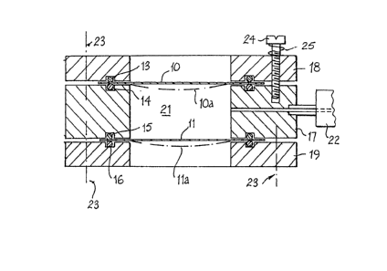
Figure 1 shows a liquid lens formed between flexible
rnembranes 10 and 11. The membranes in this example are
of high-grade plastic foil (e.g. that known under the
Trade Mark "Melinex) and have a thickness of some twelve
microns. Each membrane is clamped between a pair of
O-rings 13-16 supported in an annular frame made up of
a body 17 and two end caps 18, 19. The O-rings are
received in grooves in the frame and these are sized
to ensure each O-ring is compressed (e.g. by 380 to
500~m) against the respective membrane.
The body 17 is provided with a through-passage 20
through which a transparent liquid is fed intq a space
21 defined within the body. 17 between the membranes 1~
and 11. A syringe (part shown at 22) can be connected
. ~5 to the passage 20 to vary the volume of liquid in the
- space 21 and thus vary the shape of the membranes 10,
11. The chain line 10a shows how the membrane 10 might
appear with a reduced pressure in the space 21 and the
line lla how the membrane 11 might appear with a supra-
atmospheric pressure in the space 21.
.. Each end cap 18, 19 is clamped to the body 17 by
a number of fixing means 23. One of the fixing means
has been shown as a screw 24 threaded into the body 17
~and compressing the O-rings against the respective mem-
brane via a spring 25. The spring 25 can be omitted
and. the ~crew 24 can be replaced by ~-clamps or other
fixing means.
. Figure 2 shows a scrap section through part of the
frame of a li~uid lens, the membrane being shown at 10',
one end cap at 18', part of the body at 17', and the
sealing rings at 13', 14'. In this case, the rings 13',
.' ' ' : ' :
. . .
1321913
-- 7
14' are of non-circular cross-section and the grooves
locating them are inclined to the axis of the aperture
in the end cap 18'.
Figure 3 shows the cross-section of two O-rings
lS', 16' with a membrane 11' grasped between them. When
downward pressure is applied on the upper ring 15' at
A, and upward pressure on the lower ring 16' at B, the
resultant forces in the plane of the membrane 11' acting
at the position of contact, C, tend to move this outward,
in the direction of the arrow D. This causes radial
stretching of the membrane 11'.
The membrane 10 (11) can be silvered on either or
both of its upper and lower surfaces to create a mirror
of variable curvature. In the case of a mi~ror, one
of the membranes can be replaced by a non-flexible plate
closing off the volume 21 and in the case of a lens,
one of the flexible membranes 10 or 11 can be replaced
by a~ rigid lens to make a two-part combination lens,
one part of which is a liquid lens. Clearly locating
- 20 a rigid lens in the space 21 between two flexible mem-
branes will give rise to a three-part combination lens,
the two outer parts of which are liquid lenses. Other
combinations of liquid/solid lenses are clearly possible.
It is also possible to have liquid on the side of
25 the membrane 10/11 outside the space 21, the latter con-
taining a gas or a liquid with a different refractive
- index from that appearing outside the space 21.
Figure 4 (not drawn to scale) shows a further embodi-
ment of adjustable power lens. An anterior flexible
transparent membrane 31 is held in an outer part 33 of
an annular holder 32 between a pair of O-rings 34 and
35. A posterior membrane 36 is held in a similar manner
in an inner part 37 of the holder 32 by a further pair
of O-rings 38, 39. The cavity 40 defined in the bore
,,, ~ .
' ' ,'' '; ', ' `
~: ,
~321913
41 of the holder between the membranes 31 and 36 is filled
with a suitable liquid such as water, alcohol, gelatine
or glycerol, and an O-ring seal 42 prevents leakage of
the filling liquid between the parts 33 and 37. The
part 37 screws into the part 33 at 43. By screwing the
holder part 37 towards or away from the holder part 33,
the pressure in the cavity 40 can either be increased
causing the membranes 31, 36 to flex outwardly and the
liquid lens to become more positive,`or reduced, causing
the liquid lens to become more negative. The medium
in contact with the upper surface o~ the membrane 31
and the lower surface of the membrane 36 would normally
be air but it will be appreciated this need not be `the
case. The bore lla could contain some other gas or even
a liquid of different refractive index from that filling
the cavity 40.
The means for turning part 37 relative to part 33
of the holder 32 to effect a lens power change can take
many folms. It could, for example, be a knurled ring
44 surrounding part 33 and connected to part 37 via a
rod 45 located in an arcuate slot 46 in the part 33.
Displacement without rotation is also possible (e.g.
with an external screw clamp).
Figure 5 shows a rather more complex liguid lens
having two liquid lenses one above the other. Where
appropriate the same reference numerals have been used
in Figure 5 as were used in Figure 4 to designate similar
integers. The compound adjustable membrane autofocus
lens shown in Figure 5 has a third housing part 47 screw-
threaded into the part 37 with a separate O-ring seal
48.
The third part 47 supports an O-ring tensioned third
membrane 49 which defines a second cavity 50 inside the
bore 31a. The third part 47 can be axially adjusted
.
; ';
132~3
g
relative to the second part 37 to adjust the pressure
in the liquid filling the cavity 50. This adjustment
could be by way of a ring 51 operating in a manner similar
to that described above for the ring 44. Since membrane
36 is now common to the cavities 40 and 50 adjustment
of the pressure in one will have an effect on the power
of the liquid lens defined by the other. This may be
of advantage, but if not, can readily be compensated
for by appropriate readjustment of the other ring 44
or 51. Different liquids can be used in the two cavities
40 and 50.
- Figures 6 and 7 illustrate a lens of a relatively
compact design. As with the previous designs there are
two transparent membranes ~e.g. 23 micron thickness type
D "Mylar" (RTM) material) 31 and 36 (shown only in chain
- lines) tensioned between respective pairs of O-rings
34, 35 and 38, 39. The housing 32 comprises a pair of
annular members 52 and 53 which when interengaged with
- the membranes in place define a fluid--tight chamber of
variable volume. The 0-rings 34, 35 are pressurised
on either side of the membrane 31 by an annular fixing
plate 52a and the 0-rings 38, 39 are press~rised on either
side of the membrane 36 by an annular fixing plate 53a.
~oth fixing plates are tightened in place to tension
the respective "MYLAR" membrane by means of a ring of
screws (only shown schematically at 54J.
The annular members 52, 53 are sealed in fluid-tight
manner by an O-ring 55 designed to be located in a groove
56 in a cylindrical outer surface 57 of the member 53.
A paxt 58 of the surface 57 is screw-threaded to mesh
with a threaded part 59 of a second cylindrical surface
60 forming part of the member 52. The size of the O-
ring 55 and the dimensions of the groove 56 in which
it is located are selected (in known manner) to obtain
sufficient deformation of the O-ring to provide a good
.
;
1321913
-- 10 --
fluid-tight seal between the surfaces 57 and 60 but not
so ~reat a deformation as to make it difficult to occa-
sion relative rotation between the members 52, 53 when
the power o~ the lens is to be adjusted. The chamber
61 created in the member 52 by the seal 55 and the mem-
branes 31 and 36 could be filled with air-free distilled
water 62, for example as shown in Figure 7.
Figure 7 shows the Figure 6 embodiment fully assem-
bled and arranged to provide a negative double-concave
lens. The liquid 6~ filling the chamber 61 between the
membranes 31 and 36 is at sub-atmospheric pressure, the
pressure being adjusted by screwing the member 53 into
or out of the member 52. Screwing in will reduce the
power of the negative lens and screwing out will increase
the power of the lens.
It will be seen therefore that the lens construc--
tions shown in Figures 4 to 7 each include a piston-type
- arrangement in which one housing member moves as a sealed
piston within the other to provide a "pumpless" lens.
In each of the lens designs illustrated one of the
membranes may be replaced by a substantially rigid
solid fluid-tight transparent member which may or-may
not have a power different from unity.
A telephoto lens is a system of lenses designed
to allow a camera to photograph a magnified image of
distant objects. A zoom lens is a system of lenses which
can be adjusted by altering the physical arrangement
of the lens components therein so as to alter the overall
focal-length and field of view to give it telescopic
or near-field properties. Autofocus lenses of the kind
described above may be used in place of solid lenses
in a telephoto or zoom lens, telescope, binoculars, micro-
scope, camera, or other optical device. They may be
used in combination with fixed lenses. Thus a zoom lens
'
1321913
-- 11
can be constructed of two adjustable membrane autofocus
lenses in sequence, one having a negative and the other
a positive power. The relative positions of the lenses
do not require to be altered in order to change the focal
length of the combination. This can be done by rotating
the inner or outer part of the holder of one or the other
of the autofocus lenses.
If the anterior surface of a liquid lens ~say mem-
brane 31 in ~igure 4) is covered with a reflective coat-
ing, this produces a flexible membrane mirror. By dis-
placing the inner part 37 of the holder 32 in Figure
4, the focus of the membrane mirror 31 can be altered.
A mirror of this construction can be considered to be
an autofocus membrane mirror.
A pair of spectacles is a device consisting of two
lenses in a frame that allows the lenses to be worn before
the eyes so as to correct errors of refraction or supple-
ment deficient accommodation. Spectacles are tradition-
al~y made with solid lenses. These have the disadvantage
that the focal length is restricted (in the case of a
bifocal lens to two values) and is not adjustable on
demand. Figure 8 illustrates one possible design for
spectacles in which the solid lenses have been replaced
by autofocus lenses. The frame (shown at 70 in Figure
8) incorporates two holders 72, 72'. By rotating the
inner parts 77 and 77' in the left and right lenses,
- the focus of each lens can be adjusted over a continuous
range of values to suit the eye of the wearer -for an
object of regard at a given distance. The frame 70 may
attach directly to the part 77, in which case the outer
part 72 may fit on to part 77 by a screw- or slide-fitting
Discs 81 and 82 of transparent unbreakable plastic
or glass may be fixed to the rear and front of each liguid
lens holder so as to protect the flexible membranes 71
, .-
.. - . ~ .
., , :
.~,.
1321913
- 12 -
and 76 from dirt and damage. The discs 81 and 82 may
be clip-on or otherwise removable attachments (e.g.
bayonet or screw mounted), or they c~uld be permanently
attached. The discs 81 and 82 may themselves be solid
lenses that provide a basic correction to vision which
can be further adjusted by altering the focal lengths
of the liquid lenses. They may be planar, or they may
have a cylindrical surface to allow for the correction
of astigmatism. The surfaces of one or both discs may
be so shaped as to correct for any aberrations associated
with the liquid lens over a range of focal lengths.
The,y may be transparent or tinted (e.g. light-intensity
colour-controlled), so allowing the spectacles to be
used as sunglasses of variable focus and variable tint.
The spectacles of Figure 8 use liquid lenses of the kind
shown in Figure 4 but other designs are clearly possible.
Such spectacles may be embodied in a face mask or res-
pirator so that adjustment may be made for the wearer's
vision without requiring him to wear spectacles in addi-
'~0 tion to the mask.
This invention thus relates to novel types of liquidor semi-solid lenses which allow the focus of the lens
to be altered directly by manipulating the relative posi-
tions pf components o~ the holders of the lenses. Such
lenses may be constructed of at least one membrane held
between O-rin~s. Direct variation in the volume of the
chamber delimited by the membrane(s~ may be used to alter
the,internal pressure in the lens and so its focal length,
giving a lens of directly adjustable focus. Such liquid
lenses may be combined to produce compound lenses with
both components separately adjustable or adjustable in
some linked manner and they may be used to construct
teles,copes, zoom lenses, spectacles, cameras and a wide
range of other optical devices.
35If the means used for adjusting the pressure exerted
on the membrane is calibrated in some way, the liquid
:, `
1321913
- 13 -
lenses described above can be used by an opthalmologist
in determining the refraction of a patient or by an
optician in determining what power of spherical lens
needs to be prescribed for each eye of a patient.
The calibration is conveniently arranged to read
directly in dioptres but it is possible to have some
other graduated scale and a reference chart to relate
the scale readings to the appropriate lens power. Thus
the arrangements described could be used to provide the
calibration by marking a scale on one member and providing
a pointer, line or other reference mark on the other,
which moves along the scale as the lens power is changed.
It is envisaged that one or a few small disc-shaped
liquid lenses such as that shown in Figure 6 could be
used as replacement for the many fixed focus lenses nor-
mally used in prescribing spectacles and for other opthal-
mic purposes.
Further, if the focal length adjustment, in say
the spectacles of Figure 8, is made sufficiently easy
to operate and is manually accessible to a patient viewing
through the liquid lenses, the patient can adjust the
focal power to optimise the sharpness of focus he/she
is experiencing during a test, thereby facilitating the
selection of the correct lens powex required to compensate
for vision defects.
I~ case ageing of the membrane produces loss of
calibration accuracy, a re-adjustment facility can be
provided on each liquid lens to enable periodic re-cali-
bration. For example, this could be a separate pre-sett-
able pressure-adjusting means, or the pointer referred
to above could be capable of having its position of
attachment to the housing adjusted.
A cylindrical liquid lens of adjustable focus can
: , . .
-~
, ~
,
1321913
- 14 -
be produced by using membranes of graded thickness and
such liquid lenses can be used to correct astigmatic
errors.
It is also possible to provide a liquid lens with
an at least partial cylindrical lens by trapping the
flexible membrane between confronting O-rings held in
respective grooves that follow cylindrical surfaces.
T,hus, for example, the grooves accommodating O-rings
34 and 35 in Figure 4, rather than being coplanar as
shown, can each lie on a cylindrical surface, the O-ring
34 (say) lying on a first cylindrical surface of a given
radius and the O-ring 35 lying on a second cylindrical
surface of the same or substantially the same radius.
In a pluri-chamber liquid lens, cylindrical components
can be added to more than one of the membranes and the
axes of the two or more different cylindrical components
of the lens surfaces need not be parallel. The surfaces
followed by a confronting pair of O-rings need not be
cyiindrical if they are non-planar thus leaving open
the possibility of fabricating complex lens surface con-
tours for specific applications.
Although the tensioned regions of the membranes
disclosed thus far are circular in plan, there is no
need for this to be the case and the invention should
25 be seen to include non-circular tensioned membrane regions
In some applications a rectangular membrane could be
used and such a membrane shape can be achieved either
by using a rectangular O-ring (e.g. made from lengths
of circular section elastomeric rod mitre-joined at the
30 corners) or by using a pair of circumscribing circular
O-rings to form the primary seal of the cavity to the
membrane and to tension the membrane but contacting the
tensioned membrane within the bore of the O-rings by
a rectangular frame that defines the optical boundary
35 of the liquid lens.
- ' ' ~ '
13219~3
- 15 -
Various changes can be made to the constructions
shown in the drawings and such constructions falling within
t:he spirit and scope of the following claims represent
systems within the ambit of this invention.
, ~ ; . :.: :. .. , . :~ . : .
. ~ :, , . . . . " , .
.,. .: