Note: Descriptions are shown in the official language in which they were submitted.
13219~4
WATER TREATMENT APPARATUS
The present invention relates to apparatus for water
treatment, and, more particularly, to apparatus for
treating a stream of water flowing from a water supply
to a water utilization system comprising a head having
a water inlet adapted to be connected to said water
supply and a water outlet adapted to be connected to
said water utilization system, said head having
removably secured thereto purifying means and/or
sterilization means, or both in combination, and a
housing surrounding said means which is removably
connected to said head in water-tight relation.
Sterilization is used in the broad sense to mean
disinfection also. The means to purify and sterilize
a stream of water preferably includes a filter of
annular cross section as the purifying means and a
source of ultraviolet light within the filter as the
sterilizing means.
It has long been known (1) that impurities wbich are
suspended as particles in the water can be removed b~
mechanical filtration unless they are of such small
size as to pass through the filtering material and (2)
that ultraviolet rays can be utilized to sterilize
water. Apparatus used initially to apply this
knowledge to the purification of water was cumbersome,
expensive and inefficient.
! ~; ,. ,., ",' ~ ~ ,, ; .
132~.954
2 69912-128
More recently Ultra Dynamics Corporation has offered an
ultraviolet water purifier to the public comprising a head
removably secured to a housing which contains a filter of annular
cross section and an ultraviolet lamp within the central passage
in the filter having its one end on which the lamp harness is
located passing through the head. The lamp harness makes
connection to a conductor from a power box mounted at the side of
and adjacent to the head. While it is intended to purify and
sterilize water, it is inefficient and difficult to assemble and
service, and not satisfactory.
According to a broad aspect of the invention there is
provided an apparatus for liquid treatment comprising in
combination:
a hollow elongate housing having an open end and a closed
end,
a hollow annular elongate liquid filtration means located
within said housing and defining an annular shaped outer flow
therethrough, said filtration means including an annularly shaped
top end piece and an annularly shaped bottom end piece, said
0 bottom end piece contacting said closed end of said house,
a hollow elongate annular flow directing means, capable of
passing ultraviolet rays therethrough, located inside said
filtration means and deflning an annular shaped intermediate flow
channel between itself and said filtration means, said
intermediate flow channel being in fluid flow connection with said
outer flow channel such that fluid is directed to flow from said
outer flow channel, through said filtration means, and into said
intermediate flow channel,
, . ~ . ~
~'''
.
1- -
. . - ,:
- ~. ... . :
~321 954
2a 69~12-128
a hollow elongate tube, capable of passing ultraviolet rays
therethrough, located within said flow directing means and
defining an annular shaped inner flow channel between itself and
said flow directing means such that fluid entering the device is
forced to flow in an annularly shaped cross-sectional pattern
along the entire length of said inner flow channel after leaving
said intermediate flow channel, sald tube being closed at a first
end to form an interior chamber which is sealed from fluid in said
flow channels,
an irradiation means located in said interior chamber for
irradiating fluid in said inner flow channel and said intermediate
flow channel with ultraviolet rays,
a head unit having a fluid inlet opening in fluid flow
connection with said outer flow channel, a fluid outlet opening in
fluid flow connection with said inner fiow channel, and a central
axial opening in fluid-tight connection with the second end of
said tube,
a means for securing said head unit to said housing in fluid-
tight connection, whereby said filtration means contacts only said
head unit and said closed end of said housing when said head unit
iæ secured to said housing with the top end piece of the
filtration means contacting the head unit and the bottom end piece
of the filtration means contacting the closed end of the housing,
and
a power box located on said head unit having a receptacle
which holds said irradiation means in its location in said tube,
said power box and said irradiation means being removable from
said housing and said head unit without disturbing the fluid flow
. .. . .
; .,
~2~ 9S~
2b 69912-128
through said annular channels,
whereby, fluid entering said apparatus through said fluid
inlet opening first flows through said outer flow channel and is
forced to pass through said filter into said intermediate flow
channel to be initially irradiated by said irradiation means, then
proceeds into said inner flow channel and is forced to pass
therethrough in an annularly shaped cross-section pattern where it
continues to be irradiated by said irradiation means, and from
thereinto sald fluid outlet opening and out of said apparatus.
The means to purify and sterilize a stream of water
preferably includes an activated carbon filter as the purifying
means and source of ultraviolet light as the sterilizing means.
In its presently best known embodiment, the present invention
comprises, in cGmbination, a head having (a) a water inlet, (b) a
water outlet and (c) an assembly of parts secured thereto
including (d) filtration means and/or (e) irradiation means, (f) a
housing surrounding sa.id filtration and irradiation means having a
water-tight connection to said head. The apparatus is adapted to
be installed in a water line having a connection (a) to a water
supply and (b) to a water utilization
, ............... . . ., , . ~ :
- ~ : : . : . -:
.:
. : : .: :
~321~
system, with the supply side of the water line
connected to the water inlet and the water outlet
connected to the water utilization system.
In the drawings:
The embodiment of the invention which is presently
best known will be described and illustrated in
conjunction with the drawings in which:
FIG. 1 is a perspective view of the assembled
apparatus;
FIG. 2 iS an exploded perspective view of the
apparatus; and
FIG. 3 is a partial sectional view of the
assembled apparatus on the line 3--3 of FIG. 1
cn a somewhat larger scale.
Referring now to the drawings:
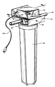
The presently best known embodiment of the invention
comprises, in combination, a head 10 having a water
inlet 12 and a water outlet 14, and an assembly of
parts mounted thereon including filtration means 18
and irradiation means 20, and a removable housing 22
having an open end 23 and a closed end 25 surrounding
said filtration and irradiation means having a water-
tight connection to said head 10. The apparatus isadapted to be installed in a water line having a
connection to a water supply 24 and to a water
utilization system 26, with the supply side of the
water line connected to the water inlet 12 and the
water outlet 14 connected to the water utilization
system 26.
- ;
, ~,
,
The housing 22 and head 10 may have any desired
configuration but the preferred configuration is
circular in cross section, as shown in the drawings.
The filtration means 18 may be any one of a number of
different types including mechanical fibers and/or
chemical adsorption materials and is preferably an
activated carbon type which is annular in cross
section having non-porous annular ends 19 making
water-tight engagement with said head 10 and said
bottom wall 25, as seen in FIG. 3, with sheets of
filter paper covering the inner and outer surfaces
enclosing the activated carbon between them. The
filter unit has an outer diameter somewhat less than
the inner diameter of the housing 22 to provide an
outer water channel 28 between them. The length of
the filter must be adequate to purify the stream of
water as it flows from channel 28 through the filter
from its outer surface to and out of the inner
surface. Lengths between about 8 to 25 inches have
been found satisfactory in use.
The inner diameter of the filtration means is somewhat
larger than the outer diameter of the irradiation
means 20 to provide an inner water channel 30 between
them into which the water flows after passing through
the filter.
In passing through the filtration means the water is
purified by mechanical removal of suspended particles
which are caught and held mechanically in the
particles of activated carbon which also purify by
chemical adsorption.
In flowing through inner channel 30, which preferably
is of short radial length, the water is sanitized by
exposure to ultraviolet rays from the irradiation
means 20.
,
-
132~9.~
In order to assure a path of flow of all the filtered
water in inner channel 30 which is long enough to
effect thorough sterilization by irradiation, a flow
directing means 32 is preferably installed in the
outlet end of the inner channel to force water
emerging into channel 30 from the filter 18 to flow in
the part of water channel 30 between the filter 18 and
the flow control means 32 toward the closed end of the
housing 22 for a significant distance, e.g., at least
about half of its length and preferably almost its
entire length. At the inner end of the flow directing
means 32 the water from that portion of the filter
opposite the flow directing means 32 joins the water
which has emerged from the other part of the filter 18
and the combined streams flow toward the head in that
portion of the channel 30 within the flow directing
means 32 to and out of the opening 33 into water
outlet 14. The flow directing means, which preferably
is a hollow cylinder of proper diameter to provide
water channels on each side of it, may be made of any
desired material but preferably is made of material
which is transparent to the ultraviolet rays, e.g.,
quartz, U-V-transparent plastic, e.g., Teflon, and ~he
like.
A bracket 34 is provided to support a power supply box
36 on the head 10, as later described, to receive
electric power of usual household voltage, e.g., 110
to 1~0 volts, through a power connection 55c and to
transform it into a proper higher voltage source of
power, which will vary according to lamp design.
The irradiation means 20 comprises an ultraviolet lamp
38, e.g., an ozone or non-ozone lamp, and a quartz
sleeve 40 which is transparent to U-V rays.
: , , : , . ............................. .
,
.
.
9 ~ ~
The quartz sleeve 40 is frictionally held in the head
10 in an accurately machined hole 46 slightly larger
in diameter than the outside diameter of sleeve 40 and
provided with grooves for 0-rings 47. This
construction assures a water-tight frictional
connection of the quartz sleeve 40 with the head 10,
permitting these parts to be handled freely as a unit.
The lamp 38 is frictionally held in power box 36 by
means of a flanged rubber sleeve 48 which is secured
to bracket 34. It tightly engages the lamp terminal
45. Terminal 45 is provided with the customary power
prongs 49 which go into electrical contacts in
electrical receptacle 42 connected by lines 44 and 44a
to the high voltage terminal (not shown) within power
box 36. This electrical connection further
frictionally supports lamp 38 in the power box 36.
The frictional connection of lamp 38 in power box 36
permits the lamp to be removed from quartz sleeve 40
while the sleeve is held in water-tight connection in
the head 10. This water-tight connection is an
important feature of the invention because it permits
the lamp to be removed from or inserted in sleeve 40,
as desired, without affecting in any way the filtering
function of the apparatus. This is of particular
importance in the multiple unit utilization of
apparatuses, as later described.
The bracket 34 is adapted to be secured to the head on
integral posts 50 by means of bolts 52 passing through
holes 53 in the bracket aligned with the screw
recesses in the ends of the posts 50. It also has a
central hole through which electrical connection is
made to lamp 38, as best seen in FIG. 2.
The power supply box 36 is fastened to bracket 34 in
any suitable manner so that it is located above the
::
-
?
~2~ 9~
head 10, e.g., by bolts 55 passing through holes 55ain flange 36a into threaded openings 55 b in bracket
34. The power supply box 36 receives current through
supply line 55c from a commercial source and supplies
it at proper higher voltage to the lamp 38 by means of
the receptacle 42 and supply lines 44 and 44a. A fuse
60 may be put in line 55c, if desired. It is also
desirable to provide means to indicate when lamp 38
is operating. For example, a crystal piece 62 may be
mounted in the depending flange of bracket 34, as seen
in FIG. 1, behind which is a light passage extending
from the surface of head 10 into the interior of the
quartz sleeve 40. When lamp 38 is illuminated, the
light passes upwardly through the light passage and
illuminates the crystal piece 62. In some cases it
may be desired to provide remote indication of the
illumination of lamp 38 and this may be done by
electronic means that operates some kind of indicator
at a remote location when lamp 38 is operating.
The head 10 and housing 22 may be connected together
by any suitable means, e.g.r an internal thread 56 in
the head 10 and an external thread 58 on the housing,
as seen in FIGS. 2 and 3, with an O-ring 59 between
them to assure water-tight connection between them.
The parts may be made of any material suitable for
exposure to water without undergoing corrosion. A
moldable and machinable plastic, such as high density
polypropylene, is a suitable material from which to
mold the head and housing because it is machinable,
rust and corrosion resistant, and it may be given
added strength, if desired, by reinforcing material
embedded in it. Stainless steel may also be used but
is not as readily workable as plastic to machine the
recess 46 for the quartz tube and the O-rings 47.
. . :
,
~2:~ 9~
The apparatus as described above may be used singly or
in multiples of two or more apparatuses with the water
supply connected to the different apparatuses in
series or parallel. This multiple use of apparatuses
is advantageous when water contains a high content of
filterable pollution because enough pieces of
apparatus may be connected together to purify the most
contaminated water. The number of the pieces of
apparatus in a multiple filtering assemblage which
have an associated lamp may be adjusted in accordance
with the bacterial content of the water being
treated, and the number of apparatuses having
irradiation means therein may vary from one to as many
as there are pieces of apparatus in the multiple
assemblage.
While the invention has been described and illustrated
in con~unction with the best currently known
embodiment, it will be obvious to those skilled in the
art that modifications and variations may be made in
it without departing from the spirit of the invention
as disclosed and the scope thereof as set forth in the
following claims.
.
. , .-. . ~ ~. ~
. .
"' ,