Note: Descriptions are shown in the official language in which they were submitted.
1322~31
l 22762-550
Contactless Heatlnq of Thln Fllaments
The lnventlon relates to the heatlng of thln fllaments
and ln partlcular to the heating of electrlcally conductive thln
f:Llaments for example for chemlcal vapour deposltlon or zone re-
finlng to produce lmproved characterlstlcs.
In the area of chemlcal vapour deposltion (CVD), hlgh
strength refractory fllaments can be formed by coatlng fine re-
fractory fllaments with hlgh strength materlals such as boron and
sillcon carblde~ Such composlte fllaments have a high strength t~
welght ratio and are useful as relnforcement materlals for pla~-
tlcs, metals and ceramlcs.
The CVD method commonly used relles on heatlng the flla-
ment substrate to a tempe~ature sufflclently hlgh to cause reac-
tlon and deposltion from raw materlals ln the vapour phase. A
problem encountered ln reslstance heatlng of the fllament sub-
strate ls ln malntalnlng good electrlcal contact wlth the fllament
to prevent varlatlons ln reslstance durlng the electrlcal heating
process. Whlle short lengths of fllament could be flxed between
carbon electrodes, lt ls extremely dlfflcult to malntaln good
electrlcal connectlon to a movlng fllament.
Dlfflcultles have been found when uslng brass, carbon or
other materlals as electrlcal contacts for movlng tungsten fila-
ments when slllcon carblde deposlts, for example, begln to bulld
up. Thls results partly from the lack of conductlvlty of the
slllcon carblde deposlt. Mercury has been used by several prevl-
ous lnvestlgators but dlfflcultles due to build up of deposlts
remain and there ls the added dlfflculty of worklng wlth a sub-
stance havlng a toxlc vapour. Use of mercury contacts ulso has
1322~31
2 2276~-550
the dlsadvantage that lt leads to contamlnatlon of the filament by
the mercury. The fllament substrate is normally fed from one reel
tc, another and attempts to malntaln electrlcal connectlons at the
feed reels rather than between two polnts on the moving fllament
has resulted ln temperature fluctuatlons due to the changes whlch
occur ln fllament reslstance.
Inductlon heatlng u~lng for example copper colls ln an
lnductlon furnace cannot be used to heat flne fllaments, accordlng
to accepted theory, slnce the skln effect llmlts the heated volume
to a thln layer around the perlphery of the wlre. The thlckness
of thls layer ls lnversely dependent on the frequency of the ln-
ductlon furnace and ls thlcker than the fllament d~ameter for 60
mlcron dlameter fllaments for hlgh frequency (HF) lnductlon fur-
naces; thls means that no net current can flow clrcumferentlally
around the wlre to heat lt up. As examplPs, 450 kHz, 13.5 MHz or
430 MHz lnductlon furnaces would have ~kln depths of about 0.05
cm, 0.01 cm or 0.0016 cm respectively, for tungsten wlre at
1200C. It ls thus necessary for the wlre dlameter to be consid-
erably greater than the skln depth for successful heatlng. Thls
argument elimlnates the possiblllty of uslng the flrst two fre-
quencies to heat a 60 mlcron tungsten filament. A further ma~or
problem i8 that the gap between the filament surface and the
copper inductlon coll must be small for efflclent heatlng but of
course thls gap ls very }arge between a thln fllament and even the
smallest dlameter water-cooled copper coil. Moreover, in the ca~e
of chemlcal vapour deposltlon a reactlon chamber, in which the
reactant vapour phase ls enclo~ed, necessltates a large gap be-
tween the filament and the copper coll. Thus thls problem also
1322~31
3 22762-550
ellmlnates use of the 430 MHz UHF frequency for heatlng a tungsten
fllament of 60 mlcron diameter. A plurality of coaxial tuned ln- -
ductlon clrcults spaced along the length of a wlre or fllament
have been descrlbed by DeBolt ln US patent No. 3754112 and by
Douglas et al ln US patent No. 3811940. Such arrangements are
compllcated, re~ulrlng lndlvldual lnductlon clrcuits to be tuned -
usually ~uarter wave tuned, and rely on the lnteractlon of elec-
trlc flelds produced thereby to cause a heating current to flow.
The ob~ect of the present lnventlon is to provide a con-
tactless heating system for thln filaments whlch allevlates the
above-mentloned dlfflcultles. Applicatlons of uch an inventlon
are extremely broad and cover a spectrum of flelds ranglng from
CVD to ceramlc slnterlng and heatlng of fllamentary conductlng or
semiconductlng extrudates.
The inventlon provldes a contactless heating apparatus
for thin fllaments comprlslng,
means to llnearly support a length of fllament~
an lnductlon coll provided ad~acent to the fllament with
lts axls parallel to the length of fllament;
a source of HF, VHF or UHF alternatlng current connected
to the coll~ and
a conducting rod connected to the one non-earthed end of
the lnductlon coil and disposed substantlally parallel to the
length of fllament~
the arrangement belng such that heating of the fllament
occurs ad~acent to the conductlng rod.
In the inventlon, as dlstinct from prlor arrangements,
the fllament to be heated ls placed outslde the coll and the
1322~31
3a 22762-550
attached rod, preferably copper as with the coll, ls posltloned at
a sultable dlstance away, typically about 2cm, and the length of
the rod determlnes the length of the heatlng zone. Typlcally the
rod ls posltloned parallel to the fllament to provlde unlform
heatlng (at red hot temperatures and above~ ln the heatlng zone.
Heatlng by thls method was unexpected and the preclse mechanlsm by
whlch energy ls transferred from the coll to the fllament ls not
understood. The rod ls preferably connected to the end turn but
may be connected to an ad~acent turn near the end of the coll.
Preferably the coll ls non-unlform in dlameter, the
dlameter belng larger at the end to whlch the rod ls attached.
Advantageously by earthing the lower end of the fllament at a
polnt remote from the coll reglon the power requlred to heat the
fllament ls reduced and a longer heated reglon ls posslble.
Advantageously the coll ls the output coll of an lnductlon furnace
and thls ls tuned and the AC voltage ralsed untll the re~ulred
power 15 reached whereby flrlng occurs le the wlre ls heated.
once this value ls known the furnace can be swltched off and on
for almost lnstant heating. Temperatures above red heat can be
varled by changlng the power. At the low temperature range,
heating is of a vibrating elongated beadllke nature. Reducing the
temperature further leads to extinguishing. On the other hand,
raising the temperature produces more unlform heatlng. Oxldatlon
or coatlng of the wire also leads to more unlform heatlng. By
sllghtly changing the posltlon of the rod or alterlng lts shape
controlled variatlons in temperature along the thin fllament (red
hot or hotter) can also be achleved. Materlals other than copper
can be used for the rod. In addition it can be in the form of a
1322~31
3b 22762-550
hollow tube. Typically the coll is made from 0.63 cm dlameter
copper tube, wlth 9 turns of lnslde diameter 3.5 cm lncreaslng to
5.2 cm at the non-earthed end (not crltlcal), the coll length
belng 8 cm. In one advantageous arrangement the AC power source
ls a Class C osclllator valve ln the lnductlon furnace. Thls
osclllator is rich in harmonics which could contribute to the
observed heatlng effect. More than one conductlng rod connected
to a coil may be disposed to heat several filaments.
4 1322~31
22762-550
The invention will now be described by way of example
only with reference to the accompanylng drawings of which:
Figure 1 illustrates the principle of the inventiQn;
Flgure 2 is a part side elevation of an arrangement of
the invention; and
Figure 3 shows the output stage of an induction furnace
providing power to the coil of the invention.
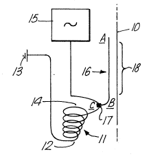
As shown in Figure 1 a filament 10, of tungsten for
example, to be heated is supported vertically. A copper
induction coil 11 is placed adjacent to the filament 10 with its
axis substantially vertical. The coil 11 is arranged such that
its top three turns are of increasingly larger diameter and wider
spaced, although this has been found not to be critical. The
small diameter end 12 is connected to earth 13 while the large
diameter end 14 is connected to a resonating oscillator 15
operated in the frequency range from HF to UHF. A copper rod 16
is attached by a clamp 17 to the end turn of the large diameter
end 14 of the coil. The copper rod 16 has a straight portion AB
disposed parallel to the filament 10 and a curved portion BC which
is engaged by the clamp 17. The straight length AB of the copper
rod determines the length of filament 18 (heating zone) which is
heated when resonant AC power is applied to the coil 11. Typically
the copper rod 16 is positioned about 2 cm from the filament 10.
Figure 2 shows a part view of a practical arrangement
in which a thin filament 20 can be fed through a cylindrical tube
21 containing a reducing gaseous mixture of argon and hydrogen at
atomo8pheric pressure. Where chemical vapour deposition is to be
; ,
~ 3%2~3~
22762-550
adopted the appropriate gases are circulated through the
cylindrical tube 21. In this arrangement copper tubing is used
both for the coil 11 and the straight portion 16. The filament
20 is fed upwardly through the cylindrical tube 21 from a spool
and the treated filament is collected by a wooden take-up spool
positioned above the tube. Where the filament enters and leaves
the tube 21 gas seals are preferably used. These gas seals
contain the reaction gases within the tube 21 while permitting
frictionless movement of the filament and preventing the ingress
of external gases and vapours into the tube. Advantageously, the
1322~31
s 22762-550
take-off spool may be earthed, but the take-up spool is made of
wood (or other non-conductor) to avold connectlon or capacltance
to earth whlch could cause unwanted RF heatlng of the wlre as lt
emerges lnto the alr between the glass apparatus and the take-up
spoo 1 .
Flgure 3 shows a conventlonal output stage of a Class C
osclllator inductlon furnace used to provlde the RF output at ter-
mlnals 31,32 to the heating coll 11. An HT source ls connected to
the anode of a YD 1162 output valve 33 and a 15 - 45 pF varlable
tunlng capacitor 34 ls provlded.
For 40 and 60 mlcron dlameter tungsten wlres the power
requlred ls of the order of 500 Watts applied to the plate of a
Class C osclllator valve ln the lnductlon furnace. The Class C
osclllator ls rlch ln harmonlcs and lt is thought that these har-
monlcs may contrlbute to the heatlng effect. Once the furnace ls
tuned and the power needed to flre the filament has been deter-
mlned then lt has been dlscovered that the flrlng of the fllament
can be swltched off and on almost lnstantaneously by swltchlng the
power source. A mlnlmum threshold exlsts below whlch flrlng wlll
not occur. The lnductlon furnace glves best results when sllghtly
off-tune. Certaln condltlon~ produce an elongated beadllke heat-
lng effect whlch can be minlmlsed by detunlng. Larger dlameter
wires re~ulre hlgher powers to heat them. Heating ls belleved to
start at about 800C upwards, wlth no upper llmlt. ~elow about
900C the heatlng 18 sllghtly elon~ated beadlike and below about
800C lt extlngulshes. Although not shown, for radlatlon safety,
the apparatus should be located ln an earthed flne mesh screen
cablnet.
:
1322~31
6 22762-550
The power source may be operated over a frequency ran~e
from HF to UHF. In addltlon to heatlng conductin~ fllaments of
tungsten, for example to coat them with slllcon carblde, the ln-
ventlon can also be used to heat composlte fllaments composed of a
conductlng lnner core and an outer semlconductlng coatlng. The
rod or tube attached to the coll can be shapsd to glve a predeter-
mlned temperature proflle along the fllament, dlfferent from the
unlform temperature achleved wlth rod and fllament parallel. The
fllament has been found to heat slgnlflcantly only opposlte the
rod and thus the heatlng zone ls well deflned. In order to tune
the lnductlon furnace lt is necessary to have at lea~t a few turns
of the coll for resonance. Although only a slngle heatlng rod has
been shown lt may be deslrable to use more than one spaced around
the fllament. In addltlon the rod may be attached to a turn of
the coll ad~acent to the end turn although thls ls not the prefer-
red arrangement. Experlments to date have demonstrated that the
lnventlon works wlth tungsten wlres dlameters of 40 to 500
mlcrons. When carbon flbre yarn was heated by thls method, the
many very fine fibre end~, of about 5 mlcron dlameter whlch pro-
trude profusely from such yarn, were found to become readlly whltehot at a low power settlng at which the bulk of the yarn dld not
reach red heat. Thls shows that the method i8 also very ef~lc-
lently able to heat flne threads of very small dlameter such as 5
mlcrons.
Mo~t of the work uslng the lnventlon has been done wlth
a 6kW lnductlon furnace worklng at 13.56 MHz (an lndustrlally
approved frequency) wlth a YD 1162 output valve. When an lnduc-
tlon furnace operatlng at a frequency of about l/2 MHz was used,
.~.
13221~`3~
7 22762-550
below the lower limlt of the HF band heating of fllaments dld not
occur. The rf power supply to the coll and attached rod ls pro-
vlded vla conductlng rods and these could be coupled to any polnt
ln the rf output clrcult. Low gas pressures are not re~ulred
slnce the inventlon works at atmospherlc pressure. The lnventlon
has also been ~hown to work at pressures other than atmospherlc
and also ln a vacuum.
Although the lnventlon has been descrlbed prlnclpally ln
relatlon to the heatlng of tunsten wlres the lnventlon has also
been demonstrated wlth a 5 mlcron dlameter sllver plated platlnum
wlre. Brass or alumlnlum may be used ln place of copper for the
coll and rod. ln addltlon the clrcular rod may be replaced by a
strlp or sheet. The strlp or ~heet may be stralght or, for
example, hellcally or otherwlse wrapped around the cyllndrical
contalnlng vessel or the space through whlch the wlre or fllament
passes. The strlp or sheet could be arranged so as to wrap sub-
stantlally or completely around the fllament. Thls last arrange-
ment however ls not so convenlent slnce lt ls not posslble to
observe the fllament.
A further posslble appllcatlon of the pre~ent lnventlon
19 the deposltion of insulatlng coatlngs on conductlng wlres. One
example would be to coat lron wlth alumlna so as to render the
wlre lnert and sultable as a relnforcement materlal.
Although the lnventlon has been descrlbed uslng a con-
tinuous rf source lt would be posslble to use a pulsed rf source.
Other modiflcatlons and appllcatlons of the lnventlon
wlll be apparent to those skllled ln the art.
~:f'