Note: Descriptions are shown in the official language in which they were submitted.
1322154- 1 -
This invention pertains to a fluid-jet-cutting
apparatus, and in particular to a fluid-jet-
cutting nozzle assembly such as is used in such
apparatus.
The nozzle assemblies to which this invention
pertains commonly comprises a nozzle body, a
nozzle, and a jet orifice element, the three being
centrally bored and disposed for longitudinal
alignment of the bores substantially along an
axis.
Due to manufacturing tolerances, and machining
imprecisions, it frequently occurs that the jet
orifice element nozzle bores are not in true,
axial alignment. Consequently, the highly-
pressured fluid jet, passing through the bore inthe element, can enter the bore in the nozzle
slightly off center, and migrate toward, and
impinge against, the wall of the nozzle bore. As
a result, and especially if the jet has abrasive
particulate therein, the nozzle bore becomes
distorted, and the nozzle itself is soon and must
be replaced.
What has been need is a fluid-jet-cutting nozzle
assembly which will for the aforesaid tolerances
and imprecisions, by allowing for axial alignment
adjustments.
It is an object of this invention to meet just
such a need.
,~,..~,~
i}, j ,;,~.
: . " : ' ' .,
~322~ 2 -
According to the above object, from a broad
aspect, the present invention provides a ~luid-
iet-cutting nozzle assembly which comprises a
body, a nozzle, and a jet orifice element. The
nozzle and element each have a fluid-accommodating
passage formed therethrough, and centrally
thereof. The body has a longitudinal axis, and
comprises means for (a) receiving the nozzle and
element therein, and (b) positioning the nozzle
and element therein, in an established, spaced-
apart disposition therebetween, along the said
axis, with the said passages in substantially
collinear alignment along the axis. Means is
supported in the body for selectively adjusting
the positioning of the element relative to the
axis
According to a still further broad aspect of the
present invention, there is provided a fluid-jet-
cutting nozzle assembly which comprises a body, a
nozzle, and a jet orifice element. The nozzle and
element each have a fluid-accommodating passage
formed therethrough and centrally thereof. The
body comprises means for (a) receiving the nozzle
and element therein, and (b) positioning the
nozzle and element therein, in a spaced-apart
disposition, with the passages in substantially
collinear alignment along a given axis. Means is
also supported in the body for selectively
adjusting the positioning of the element relative
to the given axis. The housing has a void formed
therein, between the element and the nozzle, and a
circumferential wall about the void. The element
~`.i,~}~,
-
. .
1322~
- 2a -
has a shank portion which projects into the void. The
element-positioning means comprises means which
penetrates the wall and intrudes into the void for
engaging and displacing the said portion. The element
also has a spherical-shaped body portion from which the
shan~ portion extends. The housing has means defining a
spherical-shaped socket in which the body portion of the
element is confined for selective, universal movement.
A further object of this invention, as well as the novel
features thereof, will become more apparent by reference
to the following des¢ription, taken in conjunction with
the accompanying Figures, in which:
FIG. 1 is a longitudinal cross-section of a prior
art fluid-jet-cutting nozzle assembly;
FIG. 2 is a longitudinal cross-section of an
embodiment of a fluid-jet-cutting nozzle assembly
according to the invention; and
FIG. 3 is a cross-section taken along section 3-3
of Figure 2.
E'igure 1 illustrates a fluid-jet-cutting nozzle assembly
10 similar to that shown in U.S. Patent 4,449,332 issued
on May 22, 1984 to N.J. Griffiths for a "Dispenser for a
Jet of I.iquid Bearing Particulate Abrasive Material".
The assembly 10 comprises a nozzle body 12 which holds a
nozzle 14 and a jet orifice element 16 fixed therein in
spaced-apart disposition. The body 12, element 16, and
nozzle 14 have colinearly-aligned bores 18, 20 and 22,
respectively. As is known from prior art, fluid (liquid)
under extreme pressure admitted into bore 18, is formed
into a very fine jet stream in element 16, and passes
through the bore 22 of the nozzle 14. A side port 24 is
~'"' .
.. . : : - - :: .. . ~ -
~' ~! ' ,
~ ~ 2 ~
Docket No. 0495-IR-MC
provided to admit particulate abrasive, into a mixed chamber
2~, for entrainment thereo~ with the jet stream~
Tho dash-dotted line "A" denotes the optimum, axial path for
the jet stream. However, if (due to abusive use) the nozzle
14 is de~lected, or if manufa~turing tolerances and
machining imprecisions result in misalignments of the ele-
m~nt 16 and/or nozzle 14, th~ aatual stream ~ath will be a~
shown as line "B". This causes deformation o~ the nozzle
bore, and if abrasive particulate i5 employed, especially,
the nozzle 14 is soon eroded and useless.
According to my invention, of which Figures 2 and 3 are
exemplary embodiments, the misalignments can be ov~rcome.
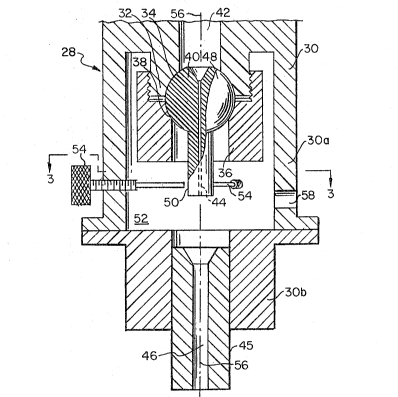
In Figure 2, only the outlet end of a nozzle assembly 28 is
shown. The nozzle body 30 comprises two, bolted together
sections 30a and 30b. Section 30a ha~ a prominent,
- externally-threaded land 32 with an arcuate seat 34 formed
thereon. A round, center-bored nut 36, with a complementary
arcuate seat 38 is received by the land 32 to retain a jet
orifice element 40 therebetween.
Th~ body section 30a has a center bore 42l the element 40
has a ~enter bore 44~ and so has the nozzle 45 a center bore
46. Element 40 has a spherical-shaped body portion 48 and a
straight shank portion 50 extending therefrom. Th~ body
poxtion 48 is captured, albeit movable in universal or
slewing directions, between the nut 36 and body section 30a.
The shank portion 50 extends into a mixing chamber 52.
I~ the ports 44 and 46 are not in true alignment, the
assembly 28 has means for making the necessary correction.
Three screws 54 are in penetration of the wall o~ body sec-
tion 3Oa and are arrayed about the shank portion 50. By
... .. . . . . .
.. :. . . . .
~322~
Docket No. 0495-IR-MC
turning the proper screws 54, the shank portion 50 can be
displacad, relative to the axis 56~ to al~gn the path o~ the
stream Qxiting the el~ment 40 with th~ bore 56 of the nozzle
4~ noa~a~y, du~ to any ~xl~l mi~all~nm~nt o~ th~
nozzla 45.
Port 58 is the entry way for abrasive particulate into the
mixlng chamber 52, if such particulate is to be used.
While I have described my invention in connection with a
specific embodiment thereof, it is to be clearly under~tood
that this is done only by way of example and not as a
limitation to the scope of my invention as set forth in the
ob;ects thereof and in the appended claims.
.: ;-` ' '. ' ~
.. . :: ~