Note: Descriptions are shown in the official language in which they were submitted.
1322~78
-- 1 --
This invention relates to a high frequency heating
apparatus, such as a microwave oven, and, more particularly,
to an attachment structure of a mounting rack thereof.
Figs. 1 to 7 show a first embodiment of the present
invention, in which:
Fig. 1 is a perspective view of a microwave oven range,
Fig. 2 is a side sectional view of the microwave oven
range,
Fig. 3 is a front sectional view of the microwave oven
range,
Fig. 4 is a developed perspective view of a shelf and a
packing, and
Figs. 5 to 7 are sectional views of a mounting portion
wherein the packing is mounted to the shelf;
Fig. 8 is a sectional view of a mounting portion wherein
a packing is mounted to a shelf according to a second
embodiment of the present invention;
Fig. 9 is a sectional view of a mounting portion wherein
a packing is mounted to a shelf according to a third
embodiment of the present invention;
Fig. 10 is a side sectional view of a mounting portion
wherein a shelf is mounted in a heating chamber in a prior
art; and
,. . .
1 322~78
- la -
Figs. 11 and 12 are sectional views of a mounting
portion wherein a packing is mounted to a shPlf in another
prior art.
Conventionally, a microwave oven range includes a
mounting rack (hereinafter referred to as a shelf) situated
at a lower portion of a housing, and on which is placed food
or the like for heating, and a radiating unit, mounted on an
upper portion of the housing, and which radiates microwaves
downward onto food placed on the shelf. However, because of
the distance between the shelf and the radiating unit, food
or the like placed on the shelf cannot always be heated
uniformly.
In the conventional microwave oven, in order to
uniformly heat an object to be heated, the following
structure has been considered to make the distance between
the microwave radiating unit and the shelf as short as
possibleO
More specifically, the conventional microwave oven range
includes an excitation port of a waveguide serving as a
microwave radiating unit and a stirrer fan in a bottom
portion of a heating chamber. In the microwave oven of this
type, the heating chamber is partitioned into upper and lower
spaces by a food mounting shelf. The stirrer fan is arranged
in the lower space partitioned by the shelf. t
The shelf for supporting food is generally a flat
`
.
1322~7~
one-piece member. Therefore when liquid food is spilled, the
spilled food may undesirably fall in to the lower stirrer fan
chamber through a gap between the shelf and a wall surface of
the heating chamber.
In the conventional manner of solving the above problem,
as shown in Fig. 10, a shelf 1 is mounted in a heating
chamber 2, and a gap between the peripheral edge of the shelf
1 and a wall surface 3 of the heating chamber 2 is filled
with a silicone material 4 to perform sealing. However, when
this sealing system is employed, a syringe is inserted
1n the small heating chamber 2, and the silicone
material must be injected with a visual observation
along the gap. This operation is time-consuming and it
is difficult to inject a uniform amount of silicone
material, thus degrading operation efficiency. In addi-
tion, when a stirrer fan 5 or the like arranged in a
lower space of the shelf l fails, the shelf 1 must be
detached during maintenance service. The sili-
cone materlal 4 filled in the gap cannot be easily
dètached, thus making it difficult to detach the shelf
1. In the worst case, parts cannot be replaced without
damaging the shelf 1 or a main body 6.
As disclosed in Japanese Patent Disclosure (Kokai)
No. 62-218736 (Figs. 11 and 12), a packing 7 is mounted
at a peripheral edge of a shelf 1, and the shelf 1 is
fitted in a heating chamber 2 from above, so that the
gap between the peripheral edge of the shelf 1 and
~ ,,
1322~78
- 3
a wall surface 3 of the heating chamber 2 is sealed by
the packing 7. When routine maintenance is to be per-
formed on this microwave oven, an upper portion of the
packing 7 mounted at the peripheral edge of the shelf 1
S is pressed by a finger and elastically deformed, making
it easy to detach from the shelf l, which in turn can
then be easily detached.
However, since a contact surface 8 between the end
face of the shelf l and the packing 7 is formed to be
perpendicular to the surface of the shelf 1, the packing
7 is urged between the shelf l and the wall surface 3 of
the heating chamber 2 and deformed in the X direction,
as shown in Fig. ll, when the shelf l in the heating
chamber 2 is pressed from above. As shown in Fig. 12,
when the shelf l is pushed downward, the packing 7
becomes detached from the shelf l, thus degrading the
sealing of the shelf l.
As described above, when the gap between the
peripheral edge of the shelf l and the wall surface 3
of the heating chamber 2 is filled with the silicone
material 4, the silicone material 4 cannot be easily
detached during maintenance service. Therefore, it is
improve the service ability, the packing 7 may be mounted at
the peripheral portion of the shelf 1 to achieve easy
detachment of the packing 7. However, as described above,
when this system is
1322~78
- 4 -
employed, the packing 7 is apt to be detached upon assembly.
The present invention provides a new and improved high
frequency heating apparatus having a sealable and detachable
mounting rack which can improve sealing of a shelf and can
facilitate assembly and disassembly of the shelf because
detachment of a packing for sealing can be prevented upon
assembly of the shelf, and the packing can be easily detached
during maintenance service.
According to the present invention, there is provided a
high frequency heating apparatus comprising: a housing
including a heating chamber having an opening at one end, a
door for exposing/closing said opening of said heating
chamber, and means for supplying a heating high frequency
output from a bottom portion of said hearing chamber to the
inside of said heating chamber; a mounting rack for
partitioning said bottom portion of said heating chamber from
an upper portion thereof, and for supporting an object to be
heated, said mounting rack having engaging portions engaged
with a lower edge of said opening of said heating chamber, by
means of which said mounting rack can pivot about said
engaging portions and be detached from said lower edge, and
having recesses respectively formed on lower surfaces of
edges opposite to wall surfaces, except for said opening; and
1322~78
sealing means for sealing a gap between a wall surface of
said heating chamber and an opposing edge of said mounting
rack, said sealing means having a projection fitted in a
corresponding one of said recesses of said mounting rack, a
base portion formed integral with said projection and brought
into tight contact with each of said opposite edges of said
mounting rack, and a tongue formed integral with said base
portion and urged against a corresponding one of the wall
surfaces of said heating chamber and creating a sealed
contact therewith.
Embodiments of the present invention will be described
hereinafter in detail, with reference to the accompanying
drawings.
,....
1322~78
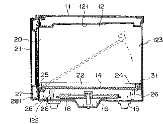
Figs. 1 to 7 show a first embodiment of the present
invention. Referring to Fig. ~, reference numeral 11 denotes
a housing of a microwave oven, and numeral 12, a high
frequency heating chamber formed within the housing 11. The
heating chamber 12 includes a ceiling portion 121 and a
bottom portion 122. An opening 20 is formed on one side of
the heating chamber 12, with wall surfaces 123, 124, and 125
being formed on the remaining three sides. A shelf 14, on
whi~h an object to be heated (not shown) in the heating
chamber 12 is placed, and having an area slightly smaller
than the effective sectional area of the heating chamber 12,
is detachably
1322~78
mounted in the heating chamber 12. More specifically,
as is shown in Fig. 2, the (sealed-in) shelf 14 is
arranged in the heating chamber 12 such that it
partitions a bottom space 13 from an upper space. The
shelf 14 is composed of polypropylene synthetic resin or
glass fiber material which is highly heat-resistant and
is substantially free from high frequency loss. As is
shown in Fig. 3, an excitation port 16 of a waveguide 15
is formed in the center of a lower surface in the bottom
space 13. High frequency waves oscillated by a
magnetron 17 are guided through the waveguide 15, and
are radiated in the heating chamber 12 via the
excitation port 16. A stirrer fan 18 is arranged above
the excitation port 16, and causes the high frequency
waves to be radiated uniformly throughout the heating
chamber 12. In addition, the opening 20 is integrally
formed with a front edge 19 of the housing 11 in which
the heating chamber 12 is formed. The opening 20 is
closed by a door 21 pivotally supported by one end of
the front edge 19.
As is shown in Fig. 2, the shelf 14 ~ is
plate-like in shape, in order for it to retain liquid
food in the event that it is spilled. Specifically,
upright portions 22, 23, and 24 are formed on the left
and right sides, and on the rear end of the shelf 14,
respectively, for this purpose. In addition, a surface
25, which is inclined downward in the forward direction,
1322~78
-- 8 --
is formed at the front end of the shelf 14, and as is
shown in Figs. 2 and 3, the shelf 14 is supported above
the bottom surface of the heating chamber 12 by a
plurality of legs 26. Located thus, the lower surface
of the front end of the shelf 14 is brought into contact
with a flange 27 formed at the front edge 19 of the
heating chamber 12.
A plurality of engaging portions 28, engaged with
the flange 27 formed at the front edge 19 of the heating
chamber 12, extend from the lower surface of the front
end of the shelf 14. When the engaging portions 28 are
engaged with the flange 27 of the front edge 19 by
sandwiching the flange 27 with their pawls 281, the
shelf 14 can be pivoted about the engaging portions 28.
Note that the pawls 281 may be omitted, and the engaging
portions 28 may be directly engaged with the flange 27.
Packings 29, 30, and 31 are detachably mounted to
the upright portions 22, 23, and 24 which are formed at
the left and right sides, and the rear end of the shelf
14, respectively. The packings 29, 30, and 31 consist
of an elastic material having heat resistance and
a sealing property, such as a silicone rubber material.
The packings 29, 30, and 31 are elongated members formed
by extrusion molding, each having a sectional shape, as
represented by the packing 31 in Fig. 5. Each packing
29, 30, or 31 includes a mounting base 32, and a tongue
33 having an interference a. The tongue 33 is urged
.: i
1322~78
... g
against a wall surface 34 of the heating chamber 12, and
is elastically defonned to be brought into tight contact
with the wall surface 34. Even if an error occurs in a
sealing size ~ (Fig. 7~, the error is absorbed by the
tongue 33. In addition, the mounting base 32 of each
packing 29, 30, or 31 includes a projection 36 fitted in
a recess 35 (to be described later) formed on the shelf
14 side, and a contact surface 38 inclined along an
inclined surface 37 (to be described later) similarly
formed on the shelf 14 side, and brought into tight
contact with the inclined surface 37.
As shown in Fig. 4, the recess 35 is formed on each
lower surface of the corresponding upright portion 22,
23, or 24 along the longitudinal direction. The
inclined surface 37 is formed on each end face of the
corresponding upright portion 22, 23, or 24 along the
longitudinal direction. In this case, as shown in
Fig. 7, the inclined surface 37 is inclined such that a
lower contact portion is located nearer the wall surface
34 of the heating chamber 12 than an upper portion with
respect to the direction perpendicular to the plate
surface of the shelf 14. The mounting base 32 of each
packing 29, 30, or 31 is slid and inserted from one end
of the corresponding upright portion 22, 23, or 24, and
the projection 36 and the contact surface 38 are fitted
in the recess 35 and the inclined surface 37, respec-
tively, as shown in Fig. 5.
~322~8
-- 10 --
In order to mount the shelf 14 in the heating
chamber 12, as indicated by a broken line in Fig. 2, the
engaging portions 28 mounted at the front end of the
shelf 14 are engaged with the flange 27 of the front
edge 19 of the heating chamber 12, and the front end of
the shelf 14 is locked. The rear end is pivoted
downward about the front end toward the inside of the
heating chamber 12, and the shelf 14 is inserted into
the heating chamber 12. Upon insertion of the shelf 14,
the tongues 33 of the packings 29, 30, and 31 are
brought into tight contact with the wall surfaces 34 of
the heating chamber 12, and are brought into slidable
contact in the direction indicated by an arrow B while
being warped in the direction indicated an arrow A,
as shown in Fig. 6. At this time, the packings 29, 30,
and 31 are sandwiched between the shelf 14 and the wall
surfaces 34 of the heating chamber 12, and urged against
the wall surfaces 34. In the packings 29, 30, and 31,
forces are dispersed in the direction indicated by an
arrow X' along the inclined surface 37. The surface 37
and the contact surface 38 are both inclined so that the
contact area of these surfaces, i.e., friction and
engaging resistance is increased, and a large force
tends not to act on the projections 36 of the packings
29, 30, and 31 respectively fitted in the recesses 35 on
the shelf 14 side. In this way, the packings 29, 30,
and 31 cannot easily be detached from the shelf 14.
~ 322578
More specifically, when the shelf 14 is mounted in
place, this prevents the packings 29, 30, and 31 from
becoming detached. As shown in Figs. 2 and 3, when the
shelf 14 is located so that the legs 26 abut against the
bottom surface of the heating chamber 12, the shelf 14
is horizontally inclined. As shown in Flg. 6, the
tongues 33 of the packings 29, 30, and 31 are warped in
the A direction (upward), and elastically brought into
tight contact with the wall surfaces 34 of the heating
chamber 12, so that the gaps between the tongues 33 and
the wall surfaces 34 are watertightly sealed.
Thus, even if liquid food is spilled during heating
thereof, it will be retained~ shelf 14, prior to
external discharge via inclined surface 25, by virtue of
the upright portions 22, 23, and 24 formed therearound
in order to prevent overflow from the shelf sides. In
addition, since the above-described packings 29, 30, and
31 are mounted on the sides (the left and right sides,
and the rear end) of the shelf 14. With the tongues 33
thereof warped in the A direction (upward) and brought
into tight contact with the wall surfaces 34 of the
heating chamber 12, in order to seal the gap between the
tongues 33 and the wall surfaces 34, this arrangement
prevents an overflow of spilled liquid food from this
portion to the bottom space 13 of the heating chamber
12. Therefore, since the bottom space 13 of the heating
chamber 12 is protected from contamination, so too are
1322~78
- 12 -
the excitation port 16 of the waveguide 15 and the
stirrer fan 18, which are arranged in this space.
When the shelf 14 is detached from the heating
chamber 12, the upper portions of the packings 29, 30,
and 31 are urged in the direction indicated by an arrow
C (downward) in Fig. 7, and the packings are elastically
deformed to decrease the thickness of their sectional
areas, so that the shelf 14 is flexed downward. Then,
the shelf 14 is moved upward about its front end, so
that the packings 29, 30, and 31 can be easily detached
downward from the shelf 14. Therefore, the shelf 14 can
be easily detached during maintenance service.
Fig. 8 shows a second embodiment of the present
invention. In this embodiment, the thickness of a
mounting base 32 of each packing 29, 30, or 31 is
decreased, and a tongue 33 is brought into contact with
a wall surface 34 of a heating chamber 12. With this
arrangement, the friction resistance between the
packings 29, 30, and 31 and the wall surfaces 34 of the
heating chamber 12 is reduced, so that the packings 29,
30, and 31 cannot be further easily detached upon
attachment of the shelf 14. The packings 29, 30, and 31
can be further easily detached during maintenance
service.
Fig. 9 shows a third embodiment of the present
invention. In this embodiment, an inclined surface 37
on a shelf 14 and a contact surface 38 on a packing 31
1322~78
are inclined in a direction opposite to that in the
first embodiment. More specifically, the surfaces 37
and 38 are inclined such that an upper contact portion
is located nearer the wall surface 34 of the heating
chamber 12 than a lower portion with respect to the
direction perpendicular to the surface of the shelf 14.
Even if this arrangement is employed, the prescribed
object of the present invention can be achieved.
Note that the present invention is not limited to
the above embodiments, and various changes and
modifications may be made.
As has been described in detail, according to the
present invention, it is provided a high frequency
heating apparatus, for supplying a high frequency wave
from a bottom portion in a heating chamber to the inside
of the heating chamber, the bottom portion of the
heating chamber is partitioned by a shelf. The front
end of the shelf is pivotally enyaged with a front
opening edge of the heating chamber, and the shelf is
pivoted about the front end serving as a fulcrum and is
mounted in the heating chamber. Packings are provided
at the left and right sides, and the rear end. The
packings are brought into tight contact with the wall
surfaces of the heating chamber to seal the gap between
the shelf and the wall surfaces of the heating chamber.
The shelf includes recesses formed on the lower surfaces
of the left, right, and rear edges, and inclined
1322578
- 14 -
surfaces formed on the end faces of the left, right, and
rear edges to be inclined in the direction perpendicular
to a plating surface of the shelf. Each packing
includes a projection fitted in the corresponding recess
in the shelf, and a contact surface inclined along the
inclined portion of the shelf and brought into tight
contact with the inclined surface on the shelf.
With the above arrangement, when the shelf is
fitted in the heating chamber by pivoting the shelf
about the front end, the force exerted on each packing
sandwiched between the shelf and each wall surface of
the heating chamber and urged against this wall surface
is dispersed along the inclined surface of the shelf.
Therefore, it is difficult to exert the force on the
projection of the packing fitted in the recess of the
shelf. Therefore, detachment of the packings from the
shelf upon its assembly can be prevented. In addltion,
when the upper portions of the packings are urged upward
by a finger, the packings are elastically deformed.
Therefore, the shelf is flexed downward, so that the
shelf can be easily detached from the packings during
maintenance service.
Thus, according to the present invention, there is
provided a high frequency heating apparatus in which the
packings can be prevented from detaching from the shelf
upon assembly but can be easily detached from the shelf
during routine maintenance, thereby rendering removal
1322~78
- 15 -
of the shelf from the heating chamber a simple and straight-
forward process. In addition, according to the present
invention, there is provided a high frequency heating
apparatus which can achieve an easy assembly operation as
compared with the case wherein the gap between the peripheral
edge of the shield and the wall surfaces of the heating
chamber is filled with the silicone material after the shelf
is mounted in the heating chamber. Also the present
invention facilitates a good outer appearance and a shelf
arrangement in the heating chamber which is highly reliable.