Note: Descriptions are shown in the official language in which they were submitted.
t 3~2~78
ST~NF.7C6 ~ PATENT
APPARATUS USING TWO-MODE OPTICAL
WAVEGUIDE WITH NON-CIRCULAR CORE
Field of the Invent~on
The present invention relates generally to optical
waveguide devices and, more specifically, to devices which
incorporate two-mode optical waveguides to control the
propagation of optical energy in the two-mode o~ waveguide.
~ackground of the Invention
An optical fiber is an optical waveguide having a
central core surrounded by an outer cladding. The refra~tive
indices of the core and cladding are selected so that optical
energy propagating in the optical fiber is well-guided by the
fiber.
As is well known in the art, a single optical fiber may
provide one or more propagation paths under certain
conditions. These propagation paths are commonly referred to
as the normal modes of a fiber, which may be conceptualized
as independent optical paths through the fiber. Normal modes
have unique electric field distribution patterns which remain
unchanged, except for amplitude as the light propagates
through the fiber. Additionally, sach normal mode will
propagate through the fiber at a unique propagation velocity.
The number of modes which may be supported by a
particular optical fiber is determined by the wavelength of
. ~ f
.
~ ,
; ', ' ~ -
' ~
t 3223 7~
the light propagating therethrough. If the wavelength is
greater that a "second order mode cutoff" wavelength (i.e.,
the frequency of the light is less than a cutoff frequency),
the fiber will support only a single mode. If the wavelength
is less than cutoff (i.e., the frequency is greater that the
cutoff frequency). the fiber will begin to support higher
order modes. For wavelengths less than but near cutoff, the
fiber will support only the fundamental, of first order mode,
and the ne~t, or second order mode. As the wavelength is
decreased, the fiber will support additional modes, for
example, third order, fourth order, etc.
Each of the normal modes (e.g., first order, second
order, etc.) are orthogonal, that is, ordinarily, there is no
coupling between the light in these modes. The orientation
of the electric field vectors of the modes defines the
polarization of the light in the mode, for example, linear
vertical or linear horizontal. A more complete discussion of
these modes, and their corresponding electric field patterns,
will be provided below.
A number of devices have been constructed to utiliæed
the orthogonality of the modes of an optical fiber to provide
selective coupling between the modes. For example, U.S.
Patent No. 4,768,851, entitled "Fiber optic Modal Coupler,"
assigned to the assignee of this invention, describes a
device which couples optical energy from the first order mode
to the second order mode, and vice versaO Canadian
Application No. 527,487, filed on January 16, lg87 and
assigned to the assignee of this invention, discloses
frequency sifters which couple optical energy from one
propagation mode to another propagation mode while shifting
the frequency of the optical energy. Canadian AppIication
No. 527,402, filed on January 15, 19~7 and assigned to the
assignee of the present invention, discloses a device which
separates optical energy propagating in one of the first
order and second order propagation modes from other of the
first order and second order propagation modes.
-2-
1 322~78
Summary of the Invention
The present invention is an optical apparatus comprising
a source of light and a waveguide having a core with a non-
circular cross section. The source of light is arranged to
introduce light signals having at least one wavelength into
the waveguide for propagation therein, ~uch that a
substantial portion of the light is at one or more
wavelengths less than a first predetermined cuto~f wavelength
of the waveguide to cause the waveguide to guide light in
both a fundamental spatial propagation mode and a higher
order spatial propagation mod2. The waveguide is sized to
provide a second predetermined cutoff wavelength for the
signals, less than the first predetermined clltoff wavelength.
The non-circular cross section of the core has cross-
sectional dimensions selected such that light guided by thewaveguide in the higher order mode at wavelengths greater
than the second predetermined cutoff wavelength propagates in
only a single, stable intensity pattern. Substantially all
of the signals introduced into the waveguide by the source of
light are at one or more wavelengths greater than the second
predetermined cutoff wavelength to cause the light signals to
propagate in only the single, spatial intensity pattern of
the higher order mode.
The fundamental spatial mode includes two polarization
modes, and preferably, the cross-sectional dimensions of the
core are further selected to cause the polarization modes of
the fundamental mode to be nondegenerate. The single
intensity pattern of the higher order ~patial mode also
includes two polarization modes, and the cross-
-3-
1 32237~ ` -
sectional dimension of the core are also preferably
selected to cause these polarization modes to be
nondegenerate. For many applications, the nondegeneracy
between polarization modes of the fundamental mode and
higher order mode preferably produces a beat length between
polarization modes on the order of 10 cm, or less, for both
sets of polarization modes.
In preferred embodiments of the invention, the
waveguide comprises an optical fiber having a core with an
elliptical cross section. The fundamental mode is the LPol
mode of the optical fiber and the higher order mode is the
LP11 mode of the optical fiber. The single intensity
pattern is the even mode intensity pattern of the LP
mode.
In one of the preferred embodiments, the invention
includes a device for inducing a periodic stress in the
optical fiber at intervals related to the beat length
between the fundamental mode and the higher order mode such
that light is cumulatively coupled between the fundamental
and higher order modes at the intervals. Preferably, the
device induces the stress by producing microbends in the
fiber.
Freguency shifting is achieved in another embodiment
of the invention by utilizing a generator to produce a
traveling flexural wave which propagates in the fiber. The
energy of the traveling flexural wave is confined to the
optical fiber and has a wavelength in the direction of
propagation selected in accordance with a beat length for
two modes of the fiber to cause light to be cumulatively
coupled from one of the modes to the other of the modes and
shifted in fre~uency.
In a further embodiment of the invention, the
waveguide comprises a ~irst optical fiber, and the
apparatus additionally comprises a second optical fiber
which is dissimilar to the first ~iber, and has at least
one spatial propagation mode. Only two of the modes of the
--4--
,
1 322~78
fibers hav~ matching propayation velocities, one of the
matching modes being in the first fiber, and other in the
second fiber. The fibers are juxtaposed to form an
interaction region in which light is transferred between
their cores. The proximity of the fiber cores at the
interaction region are selected such that light propagating
in one of the matching modes in one of the fibers is
coupled to the other of the fibers. The remainder of the
modes all have mismatched propagation velocities such that
the propagation velocity of each of the mismatched modes
differ sufficiently from all the other modes to prevent
substantial optical coupling between any of the mismatched
modes. Preferably, the cores of each of the fibers have a
cross section which is substantially the same inside the
interaction region as outside the interaction region, and
the length of the interaction region is at least an order
of magnitude larger than the maximum cross-sectional core
dimension of either of the fibers. This embodiment is
highly advantageous for use as a mode selector.
The invention is also useful for interferometry. In
an interferometer embodiment of the invention, a source of
light is used to introduce light into the waveguide such
that the light propagates in two spatial modes of the
waveguide, and such that the light propagates through a
sensing section of the waveguide for exposure to an ambient
effect. The light output ~rom the sensing section is
detected. A photodetector is arranged to intercept only a
selected portion of the spatial intensity pattern defined
by a superposition of the spatial intensity patterns of the
two modes. ~he selected portion of the spatial intensity
pattern includes substantial portions of light from both of
the two spatial modes such that the intensity pattern of
the selected mode varies in response to the ambient effect.
In accordance with another embodiment, another
photodetector is arranged to intercept another portion of
the spatial intensity pattern, and a comparing apparatus is
-5-
,. : :: : ,, - i . ~
: . . ' ;:
1 322~37~
used to compare the output of the two photodetectors to
sense the ambient effect. In one particularly preferred
embodiment, a splitting device is used to split the
selected portion of the spatial intensity pattern into two
light beams. A first polarizer is used to polarize one of
the beams to produce a first light signal. The
photodetector is positioned to receive this first light
signal. A second polarizer is used to polarize the other
of the beams to produce a second light signal, and a second
photodetector receives this second light signal. The
polarizers are oriented such that the first and second
signals have orthogonal polari~ations, and a comparing
device is used to compare the outputs of the
photodetectors. This embodiment includes a frequency
shifter which couples light from one mode to the other, and
frequency shifts the coupled light. The cross-sectional
dimensions of the core are selected to cause the
polarization modes for the fundamental mode and the
polarization modes for the higher order mode to be
nondegenerate.
The present invention also includes a polarization
selector that can selectively provide an output signal
having one of two polarizations by applying a strain to a
portion of a two-mode optical fiber. In another aspect of
the invention, a wavelength splitter splits an input
optical signal having a pair of optical wavelengths into
two output signals, each having one of the two wavelengths.
In still another aspect of the invention, the differences
in propagation characteristics of the two polarization
orientations o~ each of two spatial propagation modes in a
highly elliptical core optical fiber is utilized in a
strain gauge that measures strain and temperature by
detecting differences in the phase propagation delays in
the modes.
The invention also includes a method of propagating
light through an optical apparatus which compri~es a source
--6--
: :
~ ; .
1 ~22~7~
of light and a waveyuide having a core with a non-circular
cross section. The method includes selecting the
wavelength of the light and the cross-sectional dimensions
of the non-circular core such that (1) the waveguide
propagates light in fundamental spatial propagation mode
and a higher order spatial propagation mode and (2)
substantially all of the light in the higher order mode
propagates in only a single, stable intensity pattern.
~rief D ~
Figure 1 is a cross-sectional view of an exemplary
circular core optical fiber.
Figures 2a and 2b illustrate the electric field
intensity distribution patterns for th~ vertically
polarized and horizontally polarized HE11 (fundamental)
propagation modes of the circular core optical fiber of
Figure 1.
Figure 2c is a graph of the electric field amplitude
distribution corresponding to the intensity distribution
patterns of Figures 2a and 2b.
Figures 2d, 2e, 2f, and 2g illustrate the electric
field intensity distribution patterns for the TEol, TMo1,
even HE21 and odd HE21 (second order) propagation modes,
respectively, of the circular core optical fiber of
Figure 1.
Figure 2h is a graph of the electric field amplitude
distribution patterns for the second order modes of the
optical fiber of Figure 1.
Figures 3a and 3b illustrate the LPo1 approximations
for the first order propagation modes of the optical fiber
of Figure 1.
Figures 3c, 3d, 3e and 3f illustrate the LPll
approximations for the second order propagation modes of
the optical fiber of Figure 1.
Figure 4 is an unscaled graph o the propagation
constant of an optical waveguide versus the ellipticity of
the core of the optical waveguide.
--7--
- ' .
~ , :
.
1 32237~
Figure 5 is a cross-sectional view of an exemplary
optical fiber of the present invention having a highly
elliptical core~
Figures 6a and 6b illustrate the electric field
intensity patterns for the L~o1 (fundamental) propagation
modes of the elliptical core optical fiber of Figure 5.
Figure 6c is a qraph of the electric field amplitude
distribution for the LPo1 propagation mode of the
elliptical core optical fiber of Figure 5.
Figures 6d and 6e illustrate the electric field
intensity patterns for the even LP11 propagation modes of
the elliptical core optical fiber of Figure 5.
Figure 6f is a graph of the electric field amplitude
distribution for the even LP11 propagation modes of the
elliptical core optical fiber of Figure 5.
Figures 6g and 6h illustrate the electric field
intensity patterns for the odd LP11 propagation modes of
the elliptical core optical fiber of Figure 5.
Figure 7 is a partial cross sectional view of a bend
in an optical fiber pictorially illustrating the coupling
effect from the LPo1 optical mode to the LP11 optical mode.
Figure 8 is a pictorial illustration of the phase
relationships between the optical signals traveling in the
two propagation modes of the optical fiber of Figure 7.
Figure 9 is a pictorial representation of an optical
: fiber formed into a series of static microbends to form an
inter-modal coupler.
Figure ga is a cross section of the optical fiber of
Figure 9 taken along the lines 9a-9a, showing the
orientation of the elliptical core.
Figure 10 is a perspective illustration of the present
invention showing an optical fiber and a transducer
:~ mechanically connected to the optical fiber to induce a
series of traveling microbends in the optical fiber.
;
-8-
:,
:: :
- ..
:
1 322878
Figure lOa is a cross sectional view taXen along the
line~ lOa-lOa in Fiyure 10 showing the attachment of the
optical fiber to the transducer.
Figures lla-lle are partial elevational views showing
the operation of the transducer to generate the traveling
microbends in the optical fiber.
Figure 12 is a perspective illustration of a preferred
embodiment of a transducer to generate the traveling
microbends in the optical fiber.
Figure 13 is a cros~ sectional view of a fiber optic
mode selector using the highly elliptical core fiber of the
present invention, showing a two-mode fiber and a single
mode fiber juxtaposed in a directional coupler.
Figure 14 is a perspective view of the coupler halves
which comprise the present invention, and shows the facing
surfaces formed on the fibers mounted in each coupler half.
Figure 15 is a cross-sectional end view taken along
the lines 15-15 in Figure 13 showing the positional
relationship between the cores and the claddings of the two
fibers in Figure 13.
Figure 16a is a cross-sectional view of the single-
mode optical fiber taken along the lines 16a-16a in
Figure 13.
Figure 16b is a graphical representation of the
electric field energy distribution of an optical signal
propagating in the LPol mode of the single-mode optical
fiber in Figure 17a.
Figure 17a is a cross-sectional view of the double
mode ~iber taken along the lines 17a-17a in Figure 13.
Figure 17b is a graphical representation of the
electrical field energy distribution of the LPol
propagation mode and the LPll propagation mode of an
optical signal propagating in the two-mode fiber of Figure
17a.
, , ., ,, : : ,: :
- : . ..
.
,
1 322~7~
Figure 18a shows the single-mode optical fiber and the
two-mode optical fiber in juxtaposed relationship at their
facing surfaces~
Figure 18b graphically illustrates the interaction of
the evanescent fields of the LPl1 propagation mode of the
two mode optical fiber with the LPol propagation mode of
the sin~le-mode optical fiber.
Figure l9a is a graphical representation of the
waveform of an optical signal propagating in the LPol mode
of the single-mode optical fiber.
Figure l9b is a graphical representation of the
waveform of an optical signal propagating in the LPo1 mode
of the two-mode optical fiber.
Figure l9c is a graphical representation of the
waveform of an optical signal propagating in the LPl1 mode
of the two-mode optical fiber.
Figure 20a pictorially illustrates mismatched phase
propagation velocities of the single-mode and two-mode
optical fibers when the core axes are parallel.
Figure 20b pictorially illustrates the matching of
phase propagation velocities by positioning one of the
optical fibers at an angle with respect to the core axis of
the other optical fiber.
Figure 21 is a pictorial illustration o~ an inter-mode
~re~uency modulator that uses the apparatus of the present
invention to separate frequency-shifted light in the ~P
propagation mode from unshifted light in the LP
propagation mode.
Figure 22 is a system incorporating the mode selector
of the present invention and an evanescent field grating
reflector that separates light propagating at a particulax
frequency from light at other frequencies.
Figure 23 illustrates an exemplary segment of a two-
mode optical fiber of the present invention showing the
interrelationship of the optical beat length between the
LPol propagation modes and the LP11 even propagation modes
.
. .
. .
- .
.
1 322i37~
and the phase d~lay between the LPol modes and the LP
even modes.
Figure 24a illustrates the field intensity patterns of
the LPol modes and the LPl1 even modes for the optical
fiber of Figure 23.
Figure 24b illustrates the field intensity patterns
resulting from the superposition of the LPol and LPll modes
of the optical fiber of Figure 23 for three different phase
delays between the modes.
Figure 25a illustrates an embodiment of an
interferometer utilizing a single inter-modal coupler and
having a separate detector for detecting the upper and
lower field intensity patterns of the highly elliptical
core optical fiber.
Figure 25b is an alternative embodiment of the
interferometer of Figure 25a utilizing an offset splice in
place of the inter-modal coupler.
Figure 26 illustrates an exemplary offset splice used
in the interferometer of Figure 25b.
Figure 27a illustrates an alternative embodiment of an
interferometer utilizing the highly elliptical core optical
fiber and a pair of inter-modal couplers.
Figure 27b illustrates an alternative embodiment of
the interferometer of Figure 27a that utilizes a modal
filter or mode selector to separate the optical energy in
the two propagation modes.
Figure 28a illustrates an alternative embodiment of
the interferometer of Figure 27a that utilizes a modal
filter or mode selector to separate the optical energy in
the two propagation modes.
Figure 28b illustrates an alternative embodiment of
the interferometer of Figure 28a in which the first inter-
modal coupler is replaced with an offset splice.
Figure 28c illustrates an alternative embodiment of
the inter~erometer of Figure 28a which includes an inter-
:'
~11--
,
'. .. ; ' '', ' . ' . '' ':
,~ . ~ '. ~, ,
. . . .
t 322~7~
modal frequency shifter and a synchronous (lock-in)
amplifier to reduce or eliminate signal fading.
~ igure 29a illustrates an alternative embodiment of
the interferometer of Figure 27a that includes a reflective
s surface at one end of the sensing portion of the two-mode
optical fiber so that only one inter-modal coupler is
needed.
Figure 29b is an alternative embodiment of the
interferometer of Figure 29a in which a 50% coupler and an
offset splice are used in place of the beam splitter and
the inter-modal coupler in Figure 29a.
Figure 30 illustrates the effect of increasing
ellipticity on the propagation constants of the
polarization modes within the spatial propagation modes of
the highly elliptical core optical fiber.
Figure 31 illustrates an embodiment of an exemplary
polarization selector utilizing a highly elliptical core
optical fiber having a strain portion that can be
selectively strained to select between polarization
outputs.
Figure 32a and Figure 32b are graphs of detected
output light intensity in the horizontal polarization and
vertical polarization, respectively, for the embodiment of
Figure 31, illustrating the periodic effect of strain on
the two light intensities.
Figure 33 illustrates an alternative embodiment of a
polarization selector in which single-mode optical fibers
are positioned proximate to the two lobes in the output
intensity pattern to receive the light intensities in the
two lohes.
Figure 34 is a schematic cross-sectional view taken
along the lines 34-34 in Figur~ 33 illustrating the
positional relationship between the cores o~ the two
single-mode optical fibers with respect to the core of the
two-mode optical fiber.
-12-
,. .,. ~ . ~ . '
,' '
~ ' " ' ' ~
1 ~22~7~
Figure 35 illustrates an alternative embodiment of a
polarization selector in which a second inter-modal coupler
and a mode selector arP used to separate the light in the
two polarization modes.
Figure 36 illustrates an embodiment of a wavelength
splitter that utilizes the difference in propagation
characteristics between the LPol and LP11 propagation modes
for a selected polarization.
Figure 37a and Figuxe 37b are graphs that illustrate
the effect of optical wavelength on the amount of strain
required to cause an additional 2~ difference in the phase
between the LPo1 and LPll spatial propagation modes for two
different ~ibers and for the two polarization modes for
each fiber.
Figure 38 illustrates an embodiment of an exemplary
strain gauge that utilizes the differences in propagation
characteristics between the ~patial propagation modes and
between the polarizations for each spatial propagation mode
to detect both strain and temperature. -
Figure 39 illustrates an alternative embodiment of a
strain gauge constructed in accordance with the present
invention in which a fre~uency shiEter and a lock-in
amplifier are used to detect strain and temperature.
Figure 40 illustrates the sensing portion of the
strain gauge of Figure 39 wrapped around a mandrel to
provide a temperature sensing function.
Detailed Description of the Preferred Embodiments
The present invention utilizes an optical waveguide
that operates at a wavelength below cutoff such that the
waveguide supports both fundamental and second order guided
modes. The fundamental and second order guided modes
provide two orthogonal paths through the optical waveguide
which permits the device to be used as a two-channel
optical propagation medium. The embodiments oE the present
invention utilize an optical waveguide having the geometry
of the core selected so that only ons stable spatial
-13-
., j . ~ . . . . . .
.: ~. ' . ' ' ': ' ' : ' ' . '
- . ~
. - :
.,, : .:
,
1 32237~
orientation of the second order mode is supported in the
waveguide.
Before discussing the sp~cific embodiments of the
present invention, a detailed description of the optical
waveguide and a brief summary of the applicable mode theory
will be presented to provide background for more fully
under~tanding the invention.
Although described below in connection with a silica
glass optical fiber waveguide, one skilled in the art will
understand that the concepts presented are also applicable
to other optical waveguid~s, such as a LiNbO3 optical
fiber, integrated optics, or the like.
An exemplary cross-section of a silica glass optical
fiber 100 is illustrated in Figure 1. The fiber 100
comprises an inner core 102 and an outer cladding 104. The
inner core 102 has a radius of r. In the exemplary fiber
100, the core has a refractive index ncO and the cladding
has a refractive index nCl. As is well known in the art,
the core refractive index ncO is greater than the cladding
index nCl so that an optical signal propagating in the
optical fiber 100 is well-guided. The number of modes
guided by the optical fiber 100 depends upon the fiber
geometry and upon the wavelength of the optical signal
propagating therethrough. Typically, the wavelength above
which an optical fiber will propagate only the fundamental
or first order mode is referred to as the "second order
mode cutoff" wavelength ~c~ which may be calculated for a
circular core fiber utilizing the following equation:
2 r 2 2
Ac = -~ co ncl (1)
If the wavelength of the optical signal is greater than the
wavelength Ac (i.e., the frequency of the optical signal is
less than a cutoff frequency), only the first order or
~14-
,.
.
.
~ ~22~7~
fundamental propagation mode of the optical signal will bewell-guided by the fiber and will be propagated by the
fiber. If the wavelength of an optical signal is less than
~c (i.e., the frequency o~ the optical signal is greater
than the cutoff frequency), higher order modes, such as the
second order modes, will begin to propagate.
The true ~irst and second order modes of a circular
core optical fiber and their respective electric field
amplitude distributions are illustrated in Figures 2a-2h.
lo The two first order modes are the vertically polarized HEll
mode represented by an electric field pattern 110 in Figure
2a, and the horizontally polarized HEll mode, represented
by an electric field pattern 112 in Figure 2b. The outer
circle in each figure represents the boundary of the core
102 of the fiber 100 of Figure 1.
As illustrated in Figure 2c, the LPol modes have an
electric field amplitude distribution 116 that is
substantially symmetrical around the center line of the
core 102. The electric field amplitude distribution 116 is
concentrated in the center of the core 102 and decreases as
the distance from the center of the core 102 increases. A
small portion o~ the electric field amplitude distribution
116 often extends beyond the boundaries of the core. This
extended electric field is commonly referred to as the
evanescent field of the guided modes~
The four true second order modes are illustrated in
Figures 2d-2g. The~e ~our true modes are distinguished by
the orientation of the trans~erse electric field, denoted
by the directions of the arrows in Figures 2d-2g, and are
commonly referrPd to as the TEol mode, represented by an
electric field pattern 120 in Figure 2d; the TMol mode,
represented by an electric ~ield pattern 122 in Figure 2e;
the HE21 even mode, represented by an ele~tric field
pattern 124 in Figure 2f î and the HE21 odd mode,
repr~sented by an electric field pattern 126 in Figure 2g.
-15-
i, .. . .
., - , : , , ',: . .:
' ' , , ~ . , ; ,, ' :
:, . .
:
1 322~7~
An electric field amplitude distribution 130 for an
exemplary optical signal propagating in the second order
modes is illustrated in Figure 2h. As illustrated, the
electric field amplitude distribution 130 is substantially
equal to zero at the central line of the core, and has two
maximum amplitudes 132 and 134 near the boundary of the
core. As further illustrated, the two amplitude maxima 132
and 134 are 180 out of phase. Further, a greater portion
of the electric ~ield distribution extends beyond the
boundary of the core in the second order modes, thus
pro~iding a larger evanescent field than for the HE
modes.
Each of the four true second order modes has a
slightly different propagation velocity from the other of
the four second order modes. Thus, when two or more of the
true second order modes are co-propagating in a two-mode
fiber, the intensity distribution o~ the second order mode
varies as a function of the length of the fiber as a result
of changes in the phase differences between the four modes
as they propagate. The cross-sectional intensity
distribution of the second order mode changes in response
to environmental changes that induce di~ferential phase
shifts between the almost degenerate four modes.
In order to more easily analyze the characteristics of
optical signals propagating in the second order propagation
modes, the characteristics of the modes are analyzed using
the LP approximations for the modes defined and de~cribed
in detail in D. Gloge, I'Weakly Guiding Fibers," Applied
optics, Vol~ 10, No. 10, October 1971, pp. 2252 2258.
A bett~r understanding of the mode theory o~ optical
propagation in an opti~al fiber of other circular core
waveguide can be obtained by referring to Figures 3a-3f,
and wher~in the first and second modes are represented in
accordance with the LP approximations described by Gloge in
his paper. ~he outer circles in each of th~ illustrations
again represent the cross section of the core 10~ of the
-16-
.
: :-
s . :.
.:
~ .
1 32~87~
optical fiber lOQ of ~igure 1. The outlines within the
core circles represent the electric field distributions.
Arrows with the inner outlines represent the direction of
polarization.
Figures 3a-3b show the field patterns of the two
polarization modes in the fundamental LPo1 set of modes. A
field pattern 140 in Figure 3a represents vertically
polarized light in the LPol fundamental mode, and a field
pattern 142 in Figure 3b represents horizontally polarized
light in the fundamental ~Po1 mode.
Figures 3c-3f illustrate the LP11 approximations for
the second order modes. As illustrated in Figures 3c-3f,
there are fuur LP11 modes, each having two lobes for the
electric field distribution. Two of the modes, represented
15 by an LPll mode pattern 150 in Figure 3c and an LPl1 mode
pattern 152 in Figure 3d, are referred to herein as the
LP11 even modes. The other two LPll modes, represented by
an LPll mode pattern 154 in Figure 3e and an LPl1 mode
pattern 156 in Figure 3f, are referred to as the LPll odd
modes. The four LPll modes are distinguished by the
orientation of the lobe patterns and the orientation of the
electric field vectors (i.e., the polarization vectors)
within the lobe patterns. For example, the first LPl~ even
mode field pattern 150 (Figure 3c) has two lobes that are
symmetrically located about a horizontal zero electric
~ield line 160~ Within the two lobes, the electric field
vectors are parallel to and anti-symmetric about the zero
electric field line 160. For convenience, the LP11 mode
represented by the lobe pattern 150 will be referred to as
the horiæontally polarized LPll even mode.
The second ~P11 even lobe pattern 152 (Figure 3d) is
symmetrically located about a horizontal zero electric
field line 142. Within th~ two lobes of the field pattern
152, the electric field vectors are perpendicular to and
anti-symmetric about the zero electric field line 162. The
LP11 mode represented by the electric field pattern 152
-17-
' .
.
2~78
will be referred to as the vertically polarized LP11 even
mode.
The first LP11 odd mode field pattern 154 has two
lobes that are symmetrically located about a vertically
oriented zero electric field line 164. Within the two
lobes, the electric field vector is perpendicular to and
anti-symmetric about the zero electric field line 164, and
are thus oriented horizontally. The LP11 mode represented
by the field pattern 154 will thus be referred to as the
horizontally polarized LP11 odd mode.
The electric field pattern 156 of the second LP11 odd
mode has two lobes that are symmetrically located about a
vertically oriented zero electric field line 166. Within
the two lobes, the electric field vectors are parallel to
and anti-symmetric about the zero electric field line 166.
Thus, the LPll mode represented by the electric field
pattern 156 will be referred to as the vertically polarized
LP11 odd mode.
In the LP-mode approximations, each of the six
electric field patterns in Figures 3a-3f, namely, the two
LPo1 patterns and the four LP11 patterns, are orthogonal to
each other. In other words, in the absence of
perturbations to the optical waveguide, there is
substantially no coupling of optical energy from one of the
field patterns to any of the other field patterns. Thus,
the six electric field pattsrns may be viewed as
independent optical paths through the optical waveguide,
which ordinarily do not couple with each other.
If the indices of the core 102 and the cladding 104 o
the optical fiber 100 are approximately equal, the two LP
modes will travel through the fiber at approximately the
same propagation velo~ity, and the four second order LP11
modes will travel through the fiber at approximately the
same propagation velocity. However, the propagation
velocity for the fundamental LPo1 set of modes will be
slower than the propagation velocity for the second order
-18-
~'" '
'
'~ .
. ..
~ 3~2378
LPl1 set of modes~ Thus, the two sets of modes, LPo1 and
LPll, will move in and out of phase with each other as the
light propagates through the fiber. The propagation
distance required for the two sets of modes to move out of
phase by 360 (i.e., 2~ radians) is commonly referred to as
the beat length of the fiber, which may be mathematically
expressed as:
L _ ~ = 2~ (2)
B Qn Q~
where LB is the beat length, ~ is the optical wavelength in
a vacuum, ~n is the difference in the effective refractive
indices of the two sets of modes, and Q~ is the difference
in the propagation constants for the two sets of modes.
It has been previously shown that coherent power
transfer between the two sets of the modes, LPol and LPll,
can be achieved by producing periodic perturbations in the
- optical fiber that match the beat length of the two modes.
A number of optical devices have been constructed to
control the coupling of optical energy between the two
modes to provide useful devices for selective coupling,
filtering and frequency shifting of an optical signal.
See, for example, W.V. Sorin, et al., "Highly selective
evanescent modal filter for two-mode optical fibers,"
25 OPTICS~LETTERS, Vol. 11, No. 9, September 1986, pp. 581-
583; R.C. Youngquist, et al., "All-fiber components using
periodic coupling," IEEE Proceedin~s, Vol. 132, Pt. J, No.
5, October 1985, pp. 277-286; R.C. Youngquist, et al.,
"Two-mode fiber modal coupler," OPTICS LETTERS, Vol. 9, No.
30 5, May 1984, pp. 177-179; J.N. 81ake, et al., I'Fiber-optic
modal coupler usin~ periodic microbending," OPTICS LETTERS,
Vol. 11, No. 3, ~arch 1986, pp. 177-179: B. Y. Kim, et al.,
"All-fiber acousto-optic frequency shifter," QPTICS
LETTERS, Vol. 11, No. 6, June 1986, pp. 389-391~ and J.N.
Blake, et al., "All-fiber acousto-optic frequency shifter
using two-mode fiber," Proceedin~s o~ the SPIE, Vol. 719,
1986. The present invention provides substantial
:
~'
: ::
:, ` `:' :
.
1 322878
improvement to many of those devices and provides a number
of new devices that utilize coupling between the modes to
further control an optical signal.
Although the four LPll modes provide four orthogonal
channels for the propagation of optical energy through an
optical fiber or other waveguide, it has often been found
to be difficult to fully utiliz~ the four channels
independently. As set forth above, the LPll modes are
approximations of real modes and are nearly degenerate in a
circular core fiber 100. This makes the LPll modes very
sensitive to couplings caused by perturbations in the
optical fiber, such as bending, twisting and lateral
stressing. Furthermore, since the LPll modes are only an
approximation of the real modes, there will be a slight
amount of coupling even in the absence of perturbations of
the fiber 100. The net result is that the propagation of
an LPll mode electric field pattern in a given mode is not
stable. In like manner, the electric field patterns of te
two LPol polarization modes are likewise unstable.
It has been previously shown that the use of an
elliptical core cross-seotion in an optical fiber or other
waveguide can introduce birefringence and separate the
pxopagation constants for the two polarizations of the LPol
first order mode. The separation of the propagation
constants locks the polarization of the signal to a
principle axis of the core cross-section. It has also been
shown that an elliptical core also increases the separation
between the propagation constants of the LP11 mode
patterns. This tends to enhance modal stability. This is
illustrated in Figure 4 which is an unscaled representation
of the propagation constant ~ versus the ellipticity of the
core of an optical waveguide. As illustrated, the LPol
propagation mode has a larger ~ropagation constant than the
LPll propagation mode. From Equation (2), this difference
-20-
'
- ' .
1 322~7~
in the propaga~ion constants is related to the beat length
LB between the LPo1 and LPl1 propagation modes as follows:
~01 LB01 (3)
where ~Pol is the difference in the propagation constants
between the LPol mode and the LPll mode and Lgo1 is the
beat length between the LPo1 and LPll modes.
~ s illustrated in the left~hand portion of Figure 4,
when the core of the optical waveguide is substantially
clrcular, the LPl1 odd and even modes have substantially
the same propagation constant. However, when the core of
the optical waveguide is elliptical, the propagation
constants of the odd and even LPll modes are different.
This is illustrated by the propaqation constant difference
~11 in the right half of Figure 4. As illustrated, the
difference in the propagation constants of the odd and even
LPl1 modes (~11) increases as the ellipticity increases.
The use of an elliptical core optical fiber has been
suggested as a means of avoiding the degeneracy of the
orthogonal lobe orientations of the LPll modes. See, for
example, J. N. Blake, et al., "All-fiber acousto-optic
frequency shifter using two-mode fiber," Proceedinas of the
SPIE, Vol. 719, 1986.
The foregoing differences in the propagation constants
between the LPol mode and the odd and even LPl1 modes when
the core of the optical fiber is elliptical, also results
in a change in the cutoff wavelength and the corresponding
cutoff frequency. For example, for a circular core optical
fiber, the cutoff wavelength is related to the radius of
the fiber core, as set forth in Equation (13 above. Thus,
optical signals having wavelengths above the second order
mode cutoff wavelength ~c (i.e., frequencies below the
second order mode cutoff frequency~ will not propagate in
the second order or higher modes in the optical fiber.
Optical signals having wavelengths less than the cutoff
wavelength ~c will propagate in the second ordPr modes. If
-21-
, ~ .. ..
. ~ :
' . .'
.
.
' '' ' .
1 322878
the wavelength is further reduced to a wavelength ~c2~third order and higher modes will be supported by the
optical waveguide. For a circular core optical waveguide,
~c2 can be found by the following equation:
2~r~ncO nCl
~c2 3.832 (4)
where r, ncO and nCl are as set forth above for Equation
(1). One skilled in the art will understand that the
foregoing can also be represented by cutoff frequencies.
For example, the first cutoff wavelength ~c corresponds to
a first cutoff frequency fc~ and the second cutoff
wavelength ~c2 corresponds to a second cutoff frequency fC2
that is grater than the first cutoff frequency fc~
Specifically, for the circular core optical waveguide,
if the first cutoff frequency fc is normalized to 2.405,
the second cutoff frequency fC2 will be normalized to
3.832. In other words/ the second cutoff frequency will be
1.59 times greater than the first cutoEf frequency (e.g.,
; fc2/fc = 3-832/2.405 = 1.59). Thus, an optical signal
having a normalized frequency less than 2.405 will
propagate in the optical waveguide only in the LPo1 mode.
An optical signal having a normalized frequency in the rage
of 2.405 to 3.832 will also propagate in the second order
LPll mode. An optical signal having a normalized frequency
greater than 3.832 will propagate in higher order modes.
The foregoing relationships also apply when the core
of the optical waveguide is elliptical or has some other
non-circular geometry. For example, Allan W. Snyder and
Xue-Heng Zheng, in "Optical Fibers of Arbitrary Cross-
Sections," JournaL of the_Optical Society of America A,
Vol. 3, No. 5, May 1986, pp. 600-609, set forth the
normalization factors for a number of different wave~uide
cross sections. For example, an elliptical csre waveguide
having a major axis that is tWiC2 the length of the minor
axis, will have a normalized cutoff frequency fc f 1.889
_2~W
.
.
. ~
, .
" :
:, . . : , . : :
1 322~7~ -
when the minor axis has the same length as the diameter of
a corresponding circular core optical fiber of the same
material construction. In other words, below the
normalized frequency of 1.889, only first order LPol modes
will propagate. Similarly, Snyder and Zheng suggest that
the LPll even mode will have a normalized cutoff frequency
of 2.505, and the LP~l odd mode will have a normalized
cutoff frequency of 3.426.
Snyder and Zheng generalize the foregoing concept for
an elliptical core optical waveguide with varying ratios
between the length of the minor axis and the length of the
major axis as follows:
fc = 1.700 (l+~b/a)2)l/2 (5a)
fc2even = 1-916 (1+3(b/a)~)l/2 (5b)
fc2odd = 1-916 (3+(b/a)2)1/2 (5c)
where fc is the normalized cutoff frequency for the LPol
mode, below which optical energy will propagate only in the
LPol mode in the elliptical core optical fiber; where
fc2e~en is the normalized cutoff frequency for optical
energy propagating the LPl1 even mode, below which optical
energy will propagate only in the LPll even mode but not in
the LPll odd mode: and where f~2Odd is the normalized
cutoff frequency for the LP11 odd mode, below which optical
energy will propagate in the LP11 odd mode as well as the
LP11 even mode, but not in any of the higher order moZes; b
is one-half the length of the minor axis of the elliptical
core; and a is one-half the length of the major axis of the
elliptical core. Equations (5a), ~5b) and ~5c) can be
evaluated for an elliptical core fiber having a major axis
length 2a of twice the minor axls length 2b to obtain the
normalized frequencies 1.889, 2.505 and 3.426, set forth
above. Equations (5a), (5b) and (5c) can be further
evaluated for b = a (i.e., for a circular core) to obtain
the LPo1 cutoff frequency of 2.405 and the LPl1 cutoff
-23-
.. ,., . ~. . . .
~ ''
.~ ~.' ~ ' ' ',
.. ~ :
1 322~78
frequency of 3.832 for both the odd and even modes, as set
forth above.
The foregoing properties of the elliptical core
optical waveguide are advantageously utilized in the
present invention to improve the operating characteristics
of the optical waveguide by eliminating the LPl1 odd
propagation mode and thus provide only one spatial
oxientation for the electric field pattern of the second
order mode. Thiæ is illustrated in Figures 5 and 6a-6g.
lQ Figure 5 illustrates an exemplary optical fiber 200
having an elliptical core 202 and a surrounding cladding
204. The dimensions of the elliptical core 202 are
selected 50 that the cutoff wavelengths and ~requencies for
the two or~hogonal lobe patterns of the second order mode
are well separated. An optical signal is applied to the
fiber 200 that is within a frequency range selected to be
above the cutoff frequency fc2even and to be below the
cutoff frequency fc2Odd- For example; in an exemplary
optical fiber, haviny a first cutoff frequency fc that is
normalized to 1.889, and second frequency fc2even of 2-505~
the frequency of the input optical signal is selected to
have a normalized ~requency in the range of 1.889 to 2.505.
Thus, a light source is selected so that substantially all
of the light produced by the light source has a normalized
frequency that is substantially less than the second cutoff
frequency fc2eve~, and that has a substantial portion of
the light that has a normalized frequency that is greater
than the first cutoff frequency fc~ In terms of
wavelength, substantially all of the light produced by the
light source has one of more wavelengths that are greater
than the second cutoff wavele~th ~c2even~ and wherein a
sub~tantial portion o~ the light has at least one
wavelength that is less than the first cutoff wavelength
~c Thus, the light entering the optical fiber is caused
to propagate only in eith2r the first order LPol mode or
the LPl1 even mode. Since the frequency of the optical
-24-
- ~ `'`:' -
,
1 32~.~78
signal is selected to be less than the cutoff wavelengthfor the LP11 odd mode, substantially no light propagates in
the LPl1 odd mode.
The foregoing i5 illustrated in Figures 6a-6g. In
Figures 6a and 6b, the two polarization modes for the LPol,
first order mode are illustrated. An electric field
pattern 210 in Figure 6a represents the electric field for
the vertically polarized LPol mode, and an electric field
pattern 212 in Figure 6b represents the electric field for
the horizontally polarized LPol mode~ One skilled in the
art will understand that the optical fiber 200 tFigure 5)
is birefringent for the first order LPol mode, and that the
horizontally polarized LPol mode will propagate at a
greater velocity than the vertically polarized LPo1 mode.
An electric field amplitude distribution 214 for the LPol
propagation modes is illustrated in Figure 6c. As
illustrated, the electric field amplitude distribution 214
is similar to the electric field amplitude distribution 116
in Figure 2b, for a circular core fiber and has a peak
amplitude 216 proximate to the center line of the core 203.
Figures 6d and 6e illustrate the LPll even modes for
the elliptical core fiber 200. As illustrated in Figure 6d
and Figure 6e, respectively, a vertically polarized even
mode electric field pattern 220 and a horizontally
polarized even mode electric field pattern 222 are both
well-guided by the optical fiber 200. As illustrated in
Figure 6f, the LPl1 even mode~ have an electric field
amplitude distri~ution, represented by a curve 224, that
has a first maxima 226 proximate to one boundary of the
core, and that has a second maxima 228 proximate to an
opposite houndary of the core, and wherein the first maxima
226 and the second maxima 228 are 180~ out of phase.
The LPll odd vertical polarization mode, represented
by an electric field pattern 230 (Figure 6f), and the LPll
odd horizontal polarization modej xepre~ented by an
electric field pattern 232 ~Figure 6g), are not guided by
-25-
:
1 322878
the op~ical fiber 200 when the optical wavelength isselected to be above the second cutoff wavelength ~c2even
Thus, the optical energy in the LPll odd modes, represented
by the ~ield patterns 230 and 2~2, will not propagate.
Thus, rather than providing four degenerate optical
communication channels, such as provided by a circular core
waveguide or a slightly elliptical core waveguide, the
highly elliptical core 202 of the optical fiber 200
provides only two LPo1 mode propagation channels and two
LP11 even mode propagation channels. Furthermore, the
communication channels are well-defined and etable and, in
the absence of a perturbation in the optical fiber 200,
there is no coupling between any of the four channels.
Therefore, an optical signal can be launched in the second
order LPl1 mode and it will propagate only in the LPl1 even
mode. It is not necessary to avoid exciting the odd lobe
patterns of the second order LP11 mode because optical
energy in those lobe patterns will not propagate.
Futhermore, optical energy will not be coupled to the odd
lobe patterns.
Because of the stability of the electric field
intensity patterns of the LPo1 mode and the LPll even
modes, the performances of fiber optic devices previously
developed to utilize the second order LP11 mode will be
increased. Specific examples of devices utilizing the
highly elliptical core waveguide will be set forth
hereinafter.
Description of an Inter-Modal Coupler
It has been found that if a fiber 300, having a core
302 and a cladding 304, is bent, as illustrated in cross
section in Figure 7, a portion of the optical energy
entering the bent portion of the fiber in one mode (eOg.,
the first order LPol mode) is coupled to the orthogonal
mode (e.g., the second order LPl1 mode) as the optical
energy propagates through the bent portion of the fiber
300. One explanation for this effect is that the optical
-26-
: `' ` :
". :
`
. .
1 322~7~
energy traveling through the core 302 of the fiber 300 on
the in~ide of the bend has a shorter path than the light
traveling on the outside of the bend. Referring to Figure
7, location 306 designates the beginning of the bent
portion of the fiber 300. Location 308 designates the end
of the bent portion of the fiber 300. An electric field
amplitude distribution curve 310 is superimposed upon the
cross section of the fiber 300 at the location 306 and
illustrates that the optical energy is in the LPol mode
(i.e., the electric field amplitude distribution is
symmetrical about the center of the fiber). The curve 312
generally corresponds to the curve 214 in Figure 6c. A
se~ond optical amplitude curve 312 illustrates the
amplitude of the optical energy in the LP11 mode. In this
example, it will be assumed that there is no light in the
second order LPll mode at the location 306, and thus, the
electric ~ield distribution amplitude curve 312 is shown as
having zero magnitude. Thus, all of the optical energy is
concentrated in the LPol mode at the location 306 of the
20 fiber 300.
In the straight portion of the optical fiber before
the location 306, the LPol and LPll modes are orthogonal
and no coupling occurs. As the optical signal travels from
the location 306 to the location 308, a portion of the
optical signal travels along the center of the core,
illustrated in phantom lines by a path 320. A portion of
the optical signal also travels along an inner path 322,
illustrated in dashed lines~ which has a shorter radius
than the path 320 in the center of the fibsr core and thus
has a shorter path length. Additionally, a portion of the
optical signal travels along a path 324, also illustrated
by dashed lines, which has a larger radius than the path
320 and thus has a longer path length. Thus, an optical
signal traveling along the path 322 or any other path
~ 35 having a radius smaller than the radius of the center of
;~ the core will travel a shorter distance from the location
-27-
''' ' :
1 322~1~
306 to the location 308 than an optical signal traveling
along the path 324 or any other path having a radius
greater than the radius of the path 320. Because of the
difference in the lengths o~ the paths from the location
306 to the location 308, the optical signal which was in
phase across a cross-section of the fiber 300 at the
location 306, is no longer in phase when it reaches the
locatiorl 308. Thus, the amplitude distribution of the
optical signal at the location 308 does not correspond to
the symmetrical distribution shown in Figure 6c.
Therefore, the optical signal is no longer entirely
orthogonal to the LPll mode, and a portion of the optical
signal is coupled to the LPll mode. As illustrated in
Figure 7, at location 308 the amplitude of the signal in
the LPol mode, depicted by a curve 310' has been reduced in
amplitude. Furthermore, a curve 312', representing the
optical amplitude in the LP11 mode, no longer has a zero
magnitude. Thus, a portion of the optical energy is
transferred from the LPol mode to the LP11 mode. The
fraction of energy transferred from the LPol mode to the
LP11 mode depends upon the radius of the bend of the fiber
core 302 and upon the length of the ~iher core 302 which is
so bent. The foregoing effect is reciprocal in that light
energy input into the fiber such that it is initially
traveling in the LP11 mode is coupled to the LPol mode.
When an optical signal is traveling in the core 302 of
the fiber 300 in two different propagation modes, light
traveling in the first order LPol mode travels at a slower
phase propagation velocity than light traveling in th~
second order LP11 mode. Thus, if the light in the two
modes is from the same source and has the same ~requency,
light traveling a distance LB in the first order LPol mode
will take more time to travel the distance LB than the
light traveling the same distance in the second order LP
mode. Thus, the phase of the light in the LPol mode will
lag the phase of the light in khe LP11 mode through the
--2~--
:
,
1 322~7~
distance LB. rrhis is pictorially illustrated in Figure 8.
The light traveling in the LP1l mode is xepresented as a
series of waves 350 and the light traveling in the LPo1
mode is represented as a series of waves 352. The length
LB is selected such that if an optical wavefront traveling
in the LPo1 mode completes exactly n cycles in traveling
the LB, the light traveling in the LP11 mode will complete
exactly n-l cycles. This is illustrated in Figure 8.
Thus, when the liqht in the LPl1 mode is exactly in phase
with the light in the LPo1 mode at the beginning of the
distance L~, designated as the locations 354 and 356 on the
curves 350 and 352, respectively, the light will also be in
phase at the end of a distance LB, illustrated as locations
358 and 360 on the curves 350 and 352, respectively.
Similarly, when the light has traveled a distance of LB/2,
the light in the LP11 mode is 180 (~ radians) out of phase
with the light in the LPo1 mode, as illustrated by the
locations 362 and 364 on the curves 350 and 352,
respectively. The distance LB is referred to as the beat
length of the fiber 300 for the two propagation modes at a
selected frequency. The distance LB is calculated as set
forth above in Equation (2) as:
B ~ (2)
where ~ is the difference in the propagation constants of
the two modes along the fiber. As is well known, the
propagation constant, ~, is 2~ times the number of cycles
of a signal in a unit length, and is calculated as ~ollows:
~ = 2~ (6)
.
where ~ is the wavelength in the medium in which the signal
is propagating. As set forth above, a signal propagating
in the first order LPo1 mode propagates at a lower velocity
and thus has more cycles per unit length than the second
order or LP11 mode. Thus, a given signal at a given
frequency propagating in the first order LPo1 mode will
_~9_ --
"
' ~
:
.
1 322~7~
have a higher propagation constant ~01 than a propagation
- constant ~11 Of the same signal propagating at the same
frequency in the second order LPll mode. Returning to
Equation (2), above, the beat length LB is thus inversely
S proportional to the di~ference (~ ol ~ ~11) in the
propagation constants in the two modes. A greater
difference Q~ in the propagation constant results in a
smaller beat length, and vice versa. Typically, the
difference in the propagation constants between the first
order LPol propagation mode and the second order LPl1
propagation mode is greater than the differences in the
propagation constants between two polarizatiun modes of a
signal in a birefringent fiber. Thus, the beat lengths of
the two spatial propagation modes are shorter than the beat
lengths of the two polarization modes.
It has been found that if an optical frequency,
referred to as a center frequency, is selected to provide a
minimum beat length for the first and second order
propagation modes, the frequency of the optical signal can
be varied substantially above and below the center
frequency without causing a significant change in the
difference between the propagation constants of the two
modes. Thus, the beat length of the two propagation modes
does not vary significantly at frequencies near the center
frequency. Therefore, the heat length is r latively
insensitive to changes in optical frequency over a
relatively broad optical frequency range in comparison to
the sensitivity of the beat length between two polarization
modes of a birefringent fiber.
It has been discovered that when an optical fiber is
formed into a series of periodic bends which are spaced by
a beat length, then the coupling between the two spatial
propagation modes of an optical signal traveling through
the fiber will have a cumulative ef~ect. As illustrated in
Figure 9, a length of a fiber 400 has a series of small
bends 402, 404, 406, 408, 410, 412, 414, 416, 418 and 420,
-30-
.
1 32.~78
referred to as microbends, which are spaced apart such that
the distance between corresponding bends (i.e., between
bends in th2 same direction) is substantially equal to LB,
the beat length of an optical signal passing through the
fiber 400. The effect of each section having a length of
LB is cumulative with each other section having an length
of LB to cause a cumulative coupling of optical energy from
one mode to another mode in the fiber 400. This effect was
demon~trated in theory in Henry F. Taylor, "Bending Ef~ects
in Optical Fibers," Journal of Liqhtwave Technoloay, Vol.
LT-2, pp. 616-633 (1984). In that paper, the periodic
microbends were introduced by statically positioning the
fiber between opposing periodic structures. Thus, the
coupling between the modes was a static coupling which did
not effect any change in the frequency of te optical signal
in the coupled mode.
The optical fiber 400 of Figure 9 is preferably an
optical fiber having a highly elliptical core 420 (see
Figure 9a) such as the optical fiber 200 that was described
above in connection with Figures 5 and 6a-6h. The bends
402, 404, 406, etc. can be advantageously formed by bending
the optical fiber 400 between two ridge structures 430 and
432. For example, the two ridge structures 430 and 432 can
be formed by wrapping plural turns of copper wires 434,
436, or the like around respective suppsrting frames 440,
442. The center-to-center spacing of the turns of the
copper wires 434, 436 determines the spacing of the bends
and is preferably closely matched to the beat length LB of
the optical fiber 400. As illustrated in Figure 9, the
small bends 402, 404, 406, etc. formed in the optical fiber
400 lie in a plane. The optical ~iber 400 is positioned so
that the elliptical core 422 has its major axis lying in
the plane of the bends and oriented in the direction of the
bend~. Thus, referring to Figures 6d and 6e, the lobes of
the LPll field pattern will propagate through the optical
fiber 400 along the insides and out~idPs of the curves
-31-
~.,, ~-
.
1 322~7~
formed by the bends, thus maximizing the effects of the
bends on the coupling of optical energy between the
fundamental LPo1 and second order LPll modes.
The amount of coupling between the two modes is
dependent upon a number of factors such as bend radius,
fiber construction, the number of bends, and the lateral
pressure applied to the fibers. Preferably, a combination
of these factors are varied to achieve a desired percentage
of coupling, such as 50% coupling.
Description of a Fre~uency Shifter Using the Present
Invention
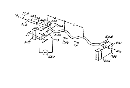
Figure 10 illustrates an embodiment of the present
invention in which a traveling periodic microbend is
introduced into a multimode fiber to cause light to be
coupled from one mode to another and to be shifted in
~requency. The present invention comprises an optical
fiber 500, having a highly elliptical core as illustrated
in Figures 5 and 6a-6h. The optical fiber 500 has a first
end portion 502 into which an optical signal, represented
by an arrow 504, is introduced at a first angular ~requency
(i.e., ~o = 2~f~). The fiber 500 is secured to a
transducer 510. In ~igure 10, the transducer 510 is
preferably a shear transducer comprising PZT (lead-
zirconium-titanate), lithium niobate (LiNbO3) or another
piezoelectric material. As shown in Figure lOa, the fiber
500 may advantageously have a small portion of its outer
cladding removed to form a flat surface 512 which rests on
a top surface 514 of the transdu¢er 510 to thereby provide
additional mechanical contact between the transducer 510
and the fiber 500. The fiber 500 can be secured to the
transducer 510 by epoxy 516 or other securing means.
The transducer 510 is driven by an electrical signal
- source 520 (shown srhematically), which, in the preferred
embodiment, is an a.c. source. When activated by the
source 520, the transducer 510 operates in the shear mode
as illustrated in Figures lla lle. The transducer 510 is
-32-
,
: , .
. .,, :,.,
. :~
,,
~ 3~2a7S~
shown in cross section in Figure lla with the fiber 500
mounted to the top surface 514 of the transducer 510. The
transducer S10 has a first side 524 and a second side 526.
At rest, the cross section of the transducer 510 is
substantially rectangular. When the electrical signal 520
is applied to the transducer 510 with a first polarity, the
transducer 510 operates in the shear mode causinq the first
side 524 and the second side 526 to be displaced in
opposite directions indicated by the arrows 528 and 530,
respectively, in Figure llb. This causes the fiber 500 to
be displaced at an angle with respect to the rest position
shown in Figure lla. When the a.c. electrical signal
applied to the transducer 510 reaches a zero crossing, the
first side 524 and second side 526 return to their rest
positions as illustrated in Figure llc, thus returning the
fiber 500 to its rest position. When the a.c. electrical
signal is applied to the transducer 510 with the opposite
polarity to the polarity applied in Figure llb, the first
side 524 and the second side 526 are displaced in
directions indicated by the arrows 532, 534 in Figure lld.
This displacement is opposite to the displacement
illustrated in Figure llb. Thus, the fiber 500 is
displaced at an angle opposite the angle of displacement in
Figure llb. When the a.c. electrical signal again reaches
zaro crossing, the first side 524 and the second side 526
again return to their rest positions and the fiber 500 thus
returns to its rest position as illustrated in Figure lle.
In the preferred embodiment, the a.c. electrical signal is
applied to the transducer 510 so that the fiber 500 is
periodically displaced to thereby induce a flexural wave in
the fiber 500 which propagates as a series of traveling
microbends along the length of the fiber 500 away from the
transducer 510. The traveling microbends have a frequency
that is determined by frequency of the a.c. source 520.
The optical fiber 500 is preferably oriented so that
the major a~is of the elliptical core is aligned with ths
~33-
'
'
:, , ~ '.':'
t 3~2~7~
movement of the transducer 510 and thus the major axis lies
on the plane of the traveling microbends. As set forth
above, this maximizes the coupling induced by the
microbends.
The present invention preferably includes a first
damper 536 formed of damping material which surrounds the
fiber 500 at a location proximate to the side 524 of the
transducer 510. Thus, any flexural wave which travels away
from the transducer 510 in the direction towards the damper
536 is suppressed. Therefore, the ~lexural waves travel
away from the transducer 510 in one direction only, as
indicated by an arrow 540 in Figure 10. The damper 536 can
advantageously be supported by a first support block 542.
Conventional optical fibers often have an outer plastic
jacket that protects the cladding of the fiber. In the
present invention, the plastic jacket is removed to expose
the cladding that is to propagate the acoustia wave. It
has been found that the damper 536 can be advantageously
formed by leaving a portion of the plastic jacket on the
fiber outside the interaction region of the fiber with the
acoustic wave. The first support block 542 can also serve
as a mounting block for the transducer 510 to hold the
transducer 510 in a fixed relationship to the damper 536.
The present invention also preferably includes a second
damper 544, formed of damping material (such as the plastic
jacket of the fiber) through which the fiber 500 passes, to
thereby suppress any further propagation of the traveling
microbends so that the microbends have no further effect
beyond the second damper 544. The second damper 544 is
preferably supported by a second support block 546. The
second damper 544 is positioned so that only a selected
length of the optical fiber 500 is affected by the
traveling microbends, thus defining an interaction length
of the optical fibsr 500. In some applications, in which a
long interaction length may be desired, the second damper
544 may not be necessary as the traveling microbend wave
-34
,
.
..
1: ~. ' ,' ' . ' '
. . , . , ~ :
1 322~7~
will be attenuated by the length of the fiber 500. The
optical fiber 500 can be suspended in air, vacuum or
another medium between the first support block 542 and the
second support block 546. The medium can be any material
which does not attenuate the traveling microbend waves and
which does not conduct any of the energy away from the
optical fiber 500. It is not necessary that the fiber 500
be taut between the first and second support blocks 542,
546, nor is it necessary that the fiber be straight so long
as the fiber 500 is not bent with a radius sufficiently
small so that the optical signal in the fiber 500 is
perturbed by the bend.
The frequency of the electrical signal applied to the
transducer 510 is chosen so that the flexural wave thus
produced has a wavelength along the fiber which is
substantially equal to the beat length LB as indicated in
Figure 10. Thus, as discussed above, the coupling of
optical energy from one propagation mode to the other
propagation mode will be reinforced in each section of the
fiber. However, unlike the previously discussed static
microbend device, khe microbends in the fiber 500 propagate
along the length of the fiber 500 at a velocity vp. The
propagation velocity vp is determined by the particular
characteristics of the fiber 500. The frequency of the
electrical signal applied to the tran~ducer 510 (referr2d
to hereinafter .as fa) is selected so that the wavelength
: (referred to hereinafter as Aa) of the propagating
microbend is substantially equal to the beat length LB.
Since the frequency fa is equal to the velocity vp divided
by the wavelength ~a, then the frequency fa is determined
. by:
fa ~a LB ( ~
The angular frequency ~a of the electrical signal is
~a = 2~fa-
-35-
:
.
' ~
-- ,
:
1 322~7~
It has been shown that when a propagating acoustic
wave causes a periodic, traveling stress on an optical
fiber, the effect of the traveling acoustic wave is to
cause light to be coupled from one polarization mode to
another polarization mode and be shifted in frequency. See
for example W. P. Risk, et al., "Single-Sideband Frequency
Shifting in Birefringent Optical Fiber," SPIE Vol. 478-
Fiber optic and ~aser Sensors II (1984), pp. 91-97, in
which this effect is discussed with respect to coupling
between polarization modes in a birefringent fiber. A
similar effect has been described for multimode fibers for
an externally applied stress to the fiber. See for
example, U.S. Patent No. 4,684,215, issued on August 8,
1987, entitled "Single-mode Fiber optic Single-sideband
Modulator," and assigned to the same assignee as the
present application. rrhus~ an optical signal, illustrated
as an arrow 550, exiting from a second end portion 552 of
the fiber 500 exits at an angular frequency ~s~ which is
shifted in frequency from the angular frequency ~0 which
was input at the first end portion 5Q2 of the fiber 500.
The frequency ~s is equal to the angular frequency ~o plus
or minus the angular frequency ~a Of the signal applied to
the transducer 510 (i.e., ~s = ~0 + ~a)- Whether the
frequency ~a is added to or subtracted from the frequency
~o is determined by whether the signal is input in the
first order LPo1 mode or the second order LPll mode and
whether or not the optical signal is propagating in the
same direction as the propagating microbend. The
embodiment of Figure 10 is bidirectional in that the
optical signal ~o can be introduced into the second end
portion 552 and thereby be caused to propagate towards the
first end portion 502 in a direction opposite the direction
of propagation of the traveling microbend.
As set forth in the above-referenced paper, "5ingle-
Sideband Frequency Shi~ting in Birefringent Optical Fiber,"
by W. P. Risk, et alO, when a traveling acoustic wave
-36-
- :. ,:, . . .
:' . ' ' " ~ '
1 3 ~
stresses an optical fiber having an optical signal
propagatinq therein in the same direction as the traveling
acoustic wave, the frPquency of the traveling acoustic wave
will be subtracted from the ~requency of the optical signal
if the optical signal is initially traveling in the slow
optical mode (a first polarization mode in the Risk paper).
On the other hand, if the optical signal is initially
traveling in the fast optical mode (a second polarization
mode in the Risk paper), the frequency of the acoustic wave
is added to the original frequency ~o of the optical
signal. A similar effect occurs when the fiber is flexed
by the traveling microbend having a frequency ~a in the
present invention. The light input in the slow LPol
optical mode at the frequency ~o is coupled from the slow
LPo1 optical mode to the fast LPll optical mode and is
downshifted in frequency by an amount Of ~a to a frequency
shown as ~11 (i.e-, ~ o ~ ~a) On the other hand,
light initially input at the frequency ~o in the fast LPl1
optical mode is shifted upward in frequency by an amount ~a
to a frequency ~01 (i.e., ~01 = ~0 + ~a) in the LPo
optical mode.
; When the acoustic wave is traveling in the opposite
direction of the light wave, the coupling from thP fast
LP11 optical mode to the slow LPo1 optical mode causes a
downshift in the frequency from the original frequency ~o
to a new frequency ~01 (i.e., ~01 = ~0 ~ ~a~. This is the
opposite effect from the frequency shift that occurs when
the optical signal and the microbends are propagating in
the same direction. Similarly, when the light initially
travels in the slow LPol optical mode, the light is coupled
to the fast LPll optical mode and shifted upward in
frequency. The coupled light has a frequency ~o (i.e.,
0 + ~a)-
The foregoing can also be considered in terms of the
summation of the propagation constants of the two optical
-- modes and the traveling microbends. For proper phase
~37-
': . -, ' ' ,` ' ~ :
,
,
.
~ 32 ~3 73
matching between the traveling microbends and the optical
signal, the propagation constants must satisfy the
following mathematical relationship:
~11 + ~a = ~01 (8)
Thus, when the optical signal is initially traveling
in the LP11 mode, the propagation constant ~a Of the
traveling microbends is added to the propagation constant
~11 Of the optical signal in the LP11 optical mode to
obtain the propagation constant ~01 O~ the LPol optical
mode as set ~orth in Equation (8) above. Similarly, when
the optical signal is initially traveling in the LPol
optical mode, the propagation constant ~a Of the traveling
microbends is subtracted from the propagation constant ~01
of the LPol mode to obtain the propagation constant ~11 of
the LPll optical mode as follows: ;
; ~01 ~ ~a = ~11 (9)
The resulting frequency of the coupled optical signal
depends upon whether the velocity of the traveling
microbends is in the same direction as the direction of
propagation of the optical signal, or in the opposite
direction of the propagation o~ the optical signal.
The frequency shifting can be expressed mathematically
by representing the light in the ~ast LP11 optical mode as
cos(~Ot - ~llZ), where ~o is the initial frequency of the
input light, t is time, and Z is the distance in the
direction of propagation 540 o~ the traveling microbends
along the fiber 500. The traveling microbends may be
represented as cos(~at - ~aZ)l where ~a is the frequency of
the traveling microbends, ~a is the propagation csnstant of
the traveling microbends and Z is the distance along the
axis of the ~iber 500 in the direction of propagation of
the microbends. The interaction of the optical signal with
the traveling microbends leads to a product term
proportional to the following expression:
35 1/2~cos~(~o+~a~t~ a)z]+cos[(~o-~a)t-(~ a)z]} (1~) -
-38-
.~
.
;, .
.. . ... . . .
. . . i : - ,
': .' :, ' ~. '' " :' .: ,
. .
~' ' ' ' ' , ' '
. . . ' '
1 322~7g
The second term of Expression (10) does not satisfy
the phase matching condition of either Equation ~8) or
Equation (9) above. The first term in the expression is
phase matched in accordance with Equation (8). This match
explicitly indicates that the optical signal in the LPo1
mode is upshifted in frequency to the frequency
'~01 ~ ~0 ~ ~a A similar analysis for interaction of an
optical signal in the LPo1 mode leads to a product term
proportional to the following expression:
1/2(cos[(~o-~a)t-(~ol-~a)z~+cos[(~o+~a)t-(~ol~a)z]} (11)
The second term in Expression (11) .is not phase
matched in accordance with either Equation (8) or Equation
(9) above. The first term does meet the phase matching
requirements of Equation (9). This explicitly indicates
that the LP11 mode is downshifted in frequency to the
frequenCy ~ o~~a
If the optical signal propagates in the opposite
direction as the traveling microbends, the traveling
microbend can be represented as cos(~a ~ ~aZ) The
interaction of an optical signal in the LPl1 mode with the
traveling microbend leads to a product term proportional to
the following expression:
/2{CS~(~O+~a)t~(~ a)Z]+cos[(~O-~a)~ +~a)z]} (12)
The first term in Expression (12) does not provide
proper phase matching in accordance wi`th either Equation
(8) or Equation (9~. The second term does provide proper
phase matching in accordance with Equation (8). Thus, when
the optical signal propagates in the opposite direction to
the traveling microbends, the light coupled to th~ LPol
mode is downshifted in frequency from.the light input in
the LPll mode to a frequency ~01 ~ ~0 ~ ~a instead of b~ing
upshifted as discussed above with regard to Expression (10)
~or light propagating in the same direction. When the
optical signal is initially in the LP~l mode and propagates
in the opposite direction as the traveling microbends, the
-39-
, , , ~ .
.~ ~
1 32~87~
interaction of the optical signal and th~ microbends leads
to a product term proporkional to the following expression:
1/2~cos(~o-~a)t-(~ol+~a)z]+cos[(~o+wa)t-(~ol-~a)z]~ (13)
The first term in Expression (13) is not properly
phase matched in accordance with either Equation (8) or
Equation (9). The second term is properly phase matched in
accordance with Equation ~9). Thus, the optical energy
coupled from the LPol mode to the LPl1 mode is shifted
upward in frequency to a frequency ~ 0 ~~ ~a
lo The present invention has many advantages. For
example, the present invention uses a highly elliptical
core two~mode fiber, and i5 operated at a frequency wherein
the LPl1 odd mode is cut o~f. Thus, optical energy in the
LP11 mode will propagate only in the LP11 even mode. Thus,
the present invention does not require precise alignment of
the major axis of the elliptical core with the input light
source.
The present invention is particularly advantageous in
that it operate~ over a broad range of optical frequencies
for the input optical signal. This advantage results from
the use of the spatial propagation modes for coupling. As
set forth above, the beat length of the two spatial
propagation modes (e.g., the LPol and LP11 modes) does not
vary significantly over a broad optical frequency range.
Thus, the beat length will match the wavelength of the
traveling microbend wave even when the optical frequency of
the input optical signal (i.e., f~ = ~o/2~) is varied over
a broad frequency range about the selected center frequency
where the optical beat length and the wavelength of the
traveling microbends match exactly. In order to take full
advantage of the characteristics of the highly elliptical
core optical fiber 500, the center frequency fo is
preferably selected to be in the central portion of the
frequency range between the first cutoff frequency fc and
the second cutoff frequency fC2 t and the frequency shifter
-40-
.
... . .
' ~
1 3~2'37~
is operated well within the range of frequencies between fc
and fc2
The frequency of the a.c. signal modulation applied to
the transducer 510 (Figure 10) can also be varied over a
relatively broad range in the present invention. The broad
range of modulation frequencies results ~rom two features
of the present invention. The first feature of the present
invention that provides for operation over a broad
modulation frequency ~ange is that it couples optical
energy between the spatial pxopagation modes. The beat
length of the two spatial propagation modes is
substantially smaller than the beat length between the
polarization modes of an optical signal at the same
frequency. Thus, the present invention operates at a
higher absolute modulation ~requency than an exemplary
device which couples optical energy between polarization
modes. The present invention operates with optical beat
lenyths of approximately 50~m to 500~m and thus can operate
with a microbend frequency of approximately 3 MHz to
50 M~z.
The second feature of the present invention that
provides for operation over a broad modulation frequency
range is that the modulation energy from the transducer 510
(Figure 10) is coupled directly into khe fiber 500 to
induce the traveling, pèriodic microbend wave. The present
invention does not require a substrate or other medium
external to the fiber 500 to conduct the modulation energy
to the fiber 500. Thu5, a relatively large percentage of
the modulation energy acts upon the fiber 500 to create the
traveling microbend wave. Therefore, for a given
modulation energy input, it is believed that a larger
percentaya of the optical energy is transferred from one
spatial propagation mode to the other spatial propagation
mode in each beat length. Thus, relatively fewer beat
lengths o~ interaction between the optical signal and the
traveling microbend wave axe required to couple
: ~ :
I ~22~7~
substantially all of the optical energy from one spatial
propagation mode to the other spatial propagation mode. It
has been shown that coupling between the spatial
propagation modes will occur even when ther~ i6 a small
percentage of deviation from the modulation wavelength
which corresponds exactly with the beat length of the two
spatial propagation modes so long as the deviation is not
allowed to accumulate to a large total percentage of
deviation over a large number of beat lengths. Thus, since
relatively ~ew beat lengths are required in the present
invention to couple the optical energy from one spatial
propagation mode to the other spatial propagation mode, the
acceptable percentage of deviation in one beat length can
be relatively large (relative to a device requiring a large
number of beat lengths). The relatively large percentage
of acceptable deviation in wavelength combined with the
relatively large absolute modulation frequency results in a
relatively broad range for the modulation frequency.
The present invention is particularly advantageous in
that the energy required to cause the coupling between the
modes is concentrated entirely within the fiber 500.
Substantially all of the energy applied to the transducer
510 is transferred to the optical fiber 500 to produce the
periodic microbends. Thus, very little, if any, energy is
wasted in the present invention. Thus, the mechanical
energy generated by the transducer 510 is utilized very
efficiently.
Figure 12 illustrates a preferred embodiment of the
frequency shifter of the present inve~tion in which the
transducer 510 of Figure 10 is replaced with a transducer
700 particularly adapted to generate the periodic
microbends described above. The transducer 700, in the
preferred embodiment comprises a rod of fused quartz having
a substantially circular cross section throughout its
length. A first end 702 of the transducer 700 has a
diameter substantially equal to the diameter of the fiber
-42~
;
. . .. . . .
: .
.
, ' ~
1 322~7~
500. For example, in one embodiment of the present
invention, the diameter of the fiber 502 and of the first end
702 of the transducer 700 is approximately equal to 100~m.
Prefe.rably, the transducer 700 and the optical fiber 500 are
fused together at a location 704 to provide good acoustic
contact between the fiber 500 and the second end 702 of the
transducer 700.
The transducer 700 has a second end 710 which has a
diameter which is sub~tantially larger than the diameter of
the ~irst end 702. For example, the second end 710 can have
a diameter of approximately two millimeters. In the
preferred embodiment, the transducer 700 is formed from a
hollow tube of fused quartz having an initial diameter of two
millimeters or larger and by drawing the quartz tube into a
form which gradually tapers from the second end 710 to the
smaller first end 702. Thus, the transducer 700 is hollow at
the second end 710 and is substantially closed o~f (i.e.,
solid) at the first end 702. Further details o~ the
construction of the preferred embodiment of the transducer
700 are set forth in copending Canadian Application No.
517,487, filed on January 16, 1~87, entitled "FIBER OPTIC
INTER-MODE COUPLING SINGLE-SIDEBAND FREQUENCY SHIFTER," and
assigned to the assignee of the present application.
A piezoelectric material 712, such as PZT, is bonded to
the second end 710 of the transducer 700 in a manner well-
known to the art. When an electrical signal, represented
-~ schematically as a signal generator 714, is applied to the
piezoelectric material 712, the piezoelectric material 712
expands and contracts in the directions indicated by the
double-headed arrow 716 and
-43-
., ~ ,
. .
':
.
1 3 2 L_ ~3 7 8
generates a series o~ acoustic wavefronts which propagate
through the transducer 700 from the second Qnd 710 to the
first end 702, as indicated by an arrow 718. At the first
end 702, the acoustic energy in the transducer 700 is
coupled directly to the optical fiber 500 at the location
704 to cause up and down movement of the fiber 500, thus
inducing a vibration in the fiber 500 which propagates away
from the location 704 as a traveling flexural wave or
traveling microbend a~ described above with respect to
Figure 10. The sur~ace of the quartz transducer 700 acts
as an acoustic funnel which concentrates the acoustic
energy developed at the second end 710. Furthermore,
substantially all of the acoustic energy applied to the
second end 710 is conducted to the first end 702 and is
15 used to induce the traveling microbend in the fiber 700. `!
As in Figure 10, the embodiment of Figure 12 further
includes the first damper 536, proximate to the location
704, to limit the travel of the microbend in the fiber 502
to one direction, indicated by an arrow 720, away from the
damper 536. The embodiment of Figure 12 also preferably
includes the second damper 544 to suppress propagation of
the microbends beyond a selected length of the fiber 500 as
discussed above.
Detailed Description of the Mode Selector
As shown in Figures 13-20b, an intPr-mode selector
comprises a first optical fiber 1100 and a second fiber
1110. The first optical fiber 1100 has an inner core 1102
and an outer cladding 1104. The second optical fiber 1110
has a highly elliptical inner core 1112 and a ollter
cladding 1114. The core 1102 of the first optical fiber
1100 has a core refractive index nCorel~ and the cladding
1104 has a cladding refractive index ncladdingl The core
refractive index and the cladding refractive index of the
first fiber 1100 are chosen such that the core refractive
index is greater than the cladding refractive index (i.e.,
ncorel > ncladding1)- Therefore, light propagating in the
-44-
~, ~
1 322~7~
core 1102 will propagate at a slower phase velocity than
light propagating in the cladding 1104. In like manner, the
core 1112 of the second optical fiber 1110 has a core
refractive index nCore2 and the cladding 1114 has a cladding
refractive index cladding nc~ ng2 which are selected so that
the core refractive index is greater khan the cladding
refractive index (i.a., nCore2 ~ nC~awin~2)~ In the prefer~ed
embodiment, the core re~ractive index, the cladding
refractive index, and the diameter of the core of the first
optical fiber 1100 are selected so that the first optical
fiber 1100 is a single-mode optical fiber at a ~elected
optical frequency fO. The core refractive index, the
cladding refractive index, and the diameter of the core of
the second optical fiber lllO are selected so that the second
optical fiber 1110 is a multimode (i.e., a two-mode) optical
fiber at the same selected optical ~requency fO. Thus, the
first optical fiber 1100 will propagate only light in the
first order LPo1 mode at the selected optical frequency. The
second optical fiber lllO will propagate light in the first
order LPo1 mode and will also propagate light in a higher
order mode, namely, the second order LP11 propagation mode.
As illustrated in Figures 15, 17a, and 18a, the core 1112 of
the second optical fiber 1110 preferably is highly elliptical
in accordance with Figure 5, and Figures 6a~6h, above. The
ellipticity of the core 1112 is selected so that, at the
frequency fO only the even lobe patterns of the LP
propagation mode will propagate in the optical fiber 1110.
The wavelength of the optical signal at fO is above the
cutoff wavelength for the LP11 odd modes so that the LP11 odd
modes do not propagate.
The first optical fiber 1100 is arcuately mounted in a
first mounting block 1120. The second optical fiber is
arcuately mounted in a second mounting block 1130. In the
preferred embodiment, the first and second mounting blocks
1120, 1130 are constructed in accordance with the teachings
- of U.S. Patent No. 4,536,058. The ~irst mounting block 1120
-45-
~",, i
'
1 322~73
has a flat mounting surface 1140 into which an arcuate slot
1142 is cut to provide a guide for the first optical fiber
lloo. As described in u.s. Patent No. 4,536,058, the slot
1142 has a depth with respect to the mounting surface 1140 at
each of two ends of the first mounting block 1120 that is
greater than the depth at the middle of the mounting surface
1140 so that when the first optiaal fiber 1100 is positioned
in the 610t 1142, a portion of the cladding 1104 on one side
of the fir~t optical fiber 1100 is proximate to the mounting
surface 1140. The mounting surface 1140 is polished so that
the cladding 1104 of the first optical fiber 1100 is
gradually removed with the surface 1140 to form a facing
surface 1144 on the cladding 1104 which has a general oval
shape that is coplanax with the surface 1140, as illustrated
~5 in Figure 14. The polishing is continued until a sufficient
amount of the cladding 1104 is removed so that the facing
surface 1144 is within a few microns of the core 1102 of the
first optical fiber 1100. In like manner, an arcuate slot
1152 is formed in a mounting surface 1150 of the second
mounting block 1130 and the second optical fiber 1110 is
po~itioned in the slot 1152. The mounting surface 1150 and
the cladding 1114 of the second fiber 1110 are polished in
the above-described manner to form a facing surface 1154.
~ As illustrated in Figure 15, the facing surface 1144 of
: 25 the first optical fiber 1100 is positioned in juxtaposed
relationship with the facing surface 1154 of the second
optical fiber 1110 to form an interaction region 1156
(labelled in Figure 14) for transferring light between the
fibers. The core 1102 of the ~irst optical fiber 1100 and
the core 1112 of the second optical fiber 1110 are spaced
apart by the thin layer of the cladding 1104 remaining
. between the facing sur~ace 1144 and the core 1102, and the
; thin layer of the cladding 1114 remaining between the facing
surface 1154 and the core 1112. The removal of the cladding
is preferably performed in accordance with the method
described in U.S. Pat~nt No. 4,536,058. The oil drop test
,
: -46-
.,, , ~ ~ ,
. ~ . . . .
~ .
1 32~7~
~escribed in U.S. Patent No. 4,536,058 is advantageously used
to deter~ine the amount of cladding removed and the proximity
of the facing surfaces 1114, 1154 to the cores 1102, 1112,
respectively. As discussed hereinafter, cladding is removed
from the first fiber 1100 and the second fiber 1110 until the
evanescent field penetration of the facing surfaces 1144,
1154 for the selected guided modes of the fibers is
sufficient to cause coupling of light between the two guided
modes.
As further illustrated in Figure 16, the two-mode
optical fiber 1110 is preferably oriented so that the major
axis of the elliptical core 1112 is normal to the facing
surface 1154.
When the facing sur~ace 1144 and the facing surface 1154
are Auperimposed, as illustrated in Figure 13, the first
fiber 1100 and the second fiber 1110 converge near the center
of the mounting blocks 1120 and 1130 and diverge gradually as
the distance away from the center of the blocks 1120 and 1130
increases. The rate of convergence and divergence of the two
fibers i~ determined by the radius of curvature o* the two
arcuate grooves, which, in one preferred embodiment, is
selected to be 25 centimeters. This radius of curvature
permits the cores of the two fibers to be positioned in close
proximity to permit the evanescent fields to interact while
limiting the length of the interaction region 1156. As
explained in detail by Digonnet, et al., in "~naly~is of
Tunable Single Mode Optical Fiber Coupler," IEEE Journal of
ouantum Electronic~, ~ol. QE-18, No. 4, April 1982, pp. 746-
754, and in U.S. Patent No. 4,556,279, the length of an
interaction region of two juxtaposed fibers is defined
principally by the
-47-
,.~, ,) .
.~ ,
..
~ - :
.. . . . .
.
.
. ' . ' ~ ' ~ ~ . , . .'
1 322~78
proximity of the cores in the interaction region,
particularly the minimum core spacing (i.e., the distance
between the cores at the centers of the facing surfaces
1144 and 1154). The length of the interaction region is
preferably at least an order of magnitude larger than the
maximum cross-sectional dimension of the core of either of
the f`ibers so that there is a substantial amount of light
transferred, and preferably a complete transfer of light
between the two fibers. The interaction region length
increases with increasing radii of curvature and the
strength o~ coupling increases with decreasing core
spacing. The radii of curvature are preferably selected to
be sufficiently large so that little, if any bending effect
is introduced into the fibers. Further, the core spacing
is preferably no less than zero so that the diameters of
the cores 1102, 1112 are uniform throughout the length of
the apparatus of the invention, and thus, no modal
perturbations are introduced by changes in the
characteristics of the fiber.
The operation of the present invention can be mor
; fully understood by referring to Figures 16a-b, 17a-b,
~` 18a-b, l9a-c and 20a-b. Figures 16a and 16b illustrate the
electric field intensity distribution for the LPol
propagation mode of an optical signal propagating in the
single-mode optical fiber 1100. As illustrated in Figure
16bo the field intensity distribution is defined by an
electric field intensity distribution graph 1200 which has
a maximum 1202 substantially in the center of the core
1102. The intensity decreases as the distance from the
center of the core 1102 increases. Most of the electric
~ield energy of the LPo1 propagation mode i~ concentrated
in the core 1102 of the ~iber 1100. However, a portion of
the electric field energy extends into the cladding 1104,
as illustrated by a field portion 1204 and a field portion
1206 of the graph 1200. The portion of the electric field
energy outside the core 1102 is referred to as the
-48-
:
- ~
' ' , ~ ~ ': ~ ,.
- ' ~
~ . .
I 32287~
evanescent field. The interaction of the evanescent fields
of two guided modes within the interaction region 1156
provides the means for coupling optical energy between the
two fibers 1100, 1110, as described in U.S. Patent No.
4,536,058. The amount of coupling is determined
principally by the length of the interaation region and the
distance between the respective cores of the two fibers.
Figures 17a and 17b illustrate the electric field
intensity distribution ~or light propagating in the LPo1
and LPll modes of the two-mode fiber 1110 at the selected
frequency. The electric field intensity distribution of
the LPol propagation mode is illustrated by a graph 1220,
and the electric ~ield distribution of the LP11 propagation
mode is illustrated by graph 1222. As discussed above with
regard to the graph 1200 in Figure 16b, the electric field
of an optical signal propagating in the LPol propagation
mode is concentrated in the core 1112 near the center of
the fiber 1110, as illustrated by a maximum 1224, and the
intensity diminishes as the distance from the center of the
core 1112 increases. A portion of the electric field
intensity distribution of the LPol propagation mode extends
into the cladding 1114 as an evanescent field, designated
as portions 1226 and 1228.
The electric field intensity distribution graph 1222
for the light propagating in the ~P11 propagation mode has
a minimum intensity 1230 near the center of the core 1112
and the intensity increases gradually as the distance from - :
: the core 1112 increases. The maximum electric field
intensity occurs at maxima 1232 and 1234 which are
proximate to the interface between the core 1112 and the
cladding 1114 of the optical fiber 1110. Note that the
intensity distribution is proportional to the ssuare of the
amplitude distribution so that the polarity of both maxima
are the same. Thus, the evallescent ~ield of an optical
signal propagating in the LPll propagation mode,
represented by electric field energy distribution portions
: -49_
: :
:
,
1 32~?)78
1236 and 1238, extends further into the cladding than the
evanescent field of the portion of an optical signal
propagating in the LPol mode of the second optical fiber
1110 .
As illustrated in Figure 17b, the optical signal
propagating in the LPo1 propagation mode of the second
optical fiber 1110 has v~ry little evanescent field
extending beyond the core 1112 of the fiber 1110 (see the
portions 1226 and 1227 of the graph 1220). In contrast,
the evanescent field of an optical signal propagating in
the LPll propagation mode extends well into the cladding
1114 of the second optical fiber 11~0 (see the portions
1236 and 1238 of the graph 1222). Thus, when a portion of
the cladding is removed from each of the two optical fibers
15 so that the cores 1112 and 1102 can be closely juxtapose~,
there is a relatively large evanescent field intensity for
the LP11 propagation mode available to interact with the
core 1102 of the first optical fiber 1100. This is
illustrated in Figures 18a and 18b, wherein the electric
20 field intensity distribution graphs 1220 and 1222 of the
second optical fiber 1110 are shown in relation to the
electric field intensity distribution graph 1200 of the
first optical fiber 1100 when the two fibers are juxtaposed
at their respective facing surfaces 1154 and 1144. As
illustrated, there is substantially no overlap of the LPol
electric field intensity distribution 1220 of the second
optical fiber 1110 with the LP~1 electric field intansity
distribution 1200 for of the first optical fiber 1100.
However, there is relatively large overlap of the
evanescent field portion 1238 of the ~Pll electric ~ield
intensity distribution 1222 of the second optical fiber
1110 with the evanescent ield portion 1204 of the LPo1
electric field intensity distribution 1200 o~ the first
optical fiber 1100. Thus, the LP11 propagation mode of the
second optical fiber 1110 and the LPol propagation mode of
the first optical fiber 1110 interact strongly as compared
-50-
:
:
.
1 322~18
to the interaction between the LPo1 modes of the two
fibers. Due to the strong interaction between the LP11
mode of the two-mode fiber 1110 and the LPo1 mode of the
single-mode fiber 1100, a relatively large amount of
optical energy is coupled between the LP11 propagation mode
of the fiber 1110 and the LPol propagation mode of the
fiber 1100. However, since there is substantially no
interaction between the LPo1 modes of the two fibers 1100,
1110, there is substantially no optical energy coupled
between the LPol propagation mode of the fiber 1110 and the
LPo1 mode of the fiber 1100. As discussed hereinafter,
coupling between the hP11 mode of the fiber 1110 and the
LPo1 mode of the fiber 1100 is enhanced by selecting the
fibers such that the propagation constants of these two
modes are the same. Similarly, coupling between the LP
modes of the fiber is inhibited by ensuring that the LPo1
modes of the fibers have substantially different
propagation constants.
~s set forth above, the two-mode optical fiber 1110
has a highly elliptical core 1112 in which only the LP11
even mode lobes can propagate in the fiber 1110 at the
selected frequency of the optical signal. By orienting the
major axis of the elliptical core 1112 so that it is normal
to the facing surface 154, maximum coupling will be
provided ~rom the LP11 mode, two-mode fiber 1110 to the
LPol mode of the single-mode fiber 1110.
As discussed above, the energy of an optical signal
propagating in the LPol mode of a fiber is confined mostly
within the core of the fiber. Thus, an optical signal in
the ~Po1 propagation mode propagates at a phase propagation
velocity which is largely determined by the refractive
index of the core of the fiber. The effec~ive refractive
index seen by the light propagating in the LPo1 propagation
mode has a value close to the value of the refractive
index of the core. In contrast to the LPol mode, the LP11
propagation mode propagates a larger fraction of optical
-51-
.
- :
1 322g78
energy in the cladding of the fiber. Thus, the phase
propagation velocity of an optical signal propagating in
the LPll propagation mode is determined by an effective
refractive index which has a value less than the refractive
index of the core and greater than the refractive index of
the cladding. Accordingly, the effective refractive index
for light in the LP11 propagation mode has a value which is
less than that for light in the LPol propagation mode.
Thus, the phase propagation velocity of an optical signal
propagating in the LP11 propagation mode is faster than the
phase propagation velocity of an optical signal propagating
in the LPo1 mode. Due to the dif~erence in phase
velocities of the LPo1 and LPl1 modes, these modes do not
easily couple, rather, they tend to function as two
independent optical paths. In the preferred embodiment,
selective coupling between the LP11 mode of the fiber 1110
and the LPo1 mode of the fiber 1100 is accomplished by
utilizing dissimilar fibers such that the phase propagation
velocity of the LPll mode of the fiber 1110 matches the
phase propagation veloci*y of the ~Po1 mode of the fiber
1100, while the phase propagation velocities of all other
pairs of modes are not matchedO
From the foregoing, it will be understood that the
propagation velocity of an optical signal propagating in
the LPo1 mode of the first (single-mode) optical fiber 1100
is determined in part by a combination of the refractive
index of the core 1102, the refractive index of the
cladding 1104, and the diameter of the core 1102.
Similarly, the phase propagation velocities of optical
signals propagating in the LPo1 mode and the ~P11 mode of
the second (two-mode) optical fiber 1110 are determined by
the combination of the refractive index of the core 1122,
the refractive index of the cladding 1124, and the diameter
of the core 1122. As set forth the above, th~ phase
propagation velocity of an optical signal propagating in
the LP11 mode in the optical fiber 1110 will be greater
-52
1 322~7~
than the phase propagation velocity of an optical signal
propagating in the LPo1 mode of the optical fiber 1110. In
the present invention, the first optical fiber 1100 and the
second optical fiber 1110 are selected to have
characteristics (i.e., refractive indices and core
dimensions) such that the phase propagation velocity of an
optical signal in the LPll propagation mode of tha second
optical fiber 1110 i~ makched to the phase propa~ation
velocity of an optical signal in the LPo1 propagation mode
of the first optical fiber llOo. Thus, the phase
propagation velocity of an optical signal propagating in
the LP~1 mode in the second optical f~ber will be slower
than the phase propagation velocity of an optical signal
propagating in the LPll mode of the second optical fiber
1110 and will also be slower than the phase propagation
velocity of an optical signal propagating in the LP~1 mode
of the first optical fiber 1100. The relationship among
the phase propagation velocities is illustrated in Figures
l9a, l9b, and l9c.
In Figure l9a, a traveling wave 1250 represents the
phase propagation of a signal propagating in the LPol
propagation mode of the first (single mode) optical fiber
1100. The traveling wave 1250 has a first wavelength ~1
which is defined ~y a velocity Vl of the optical signal in
25 the LPo1 propagation mode of the fiber 1100 and the
; selected optical frequency fo (i.e., ~1 = Vl/fo).
Similarly, Figure l9b illustrates a traveling wave 1252
that represents the phase propagation of a signal traveling
in the hPol propagation mode of the second (two-mode~
optical fiber 1110 at the selected optical frequency fo.
The traveling wave 1252 has a wavelength ~2 which is
defined by a velocity V2 of the optical signal in the LPol
propagation mode of the second optical fiber lI10 and the
selected optical frequency fo (i.e., ~2 = V2/fo) Figure
35 l9c illustrates a traveling wave 1254 which represents the
phase propagation of a signal traveling in the LP
-53-
- . .
- . :.................... .
' ' ~ ~, ' ~ , .
. : .. :. ,. -
1 322~7~
propagation mode of the optical fiber 1110 at the selected
optical frequency f0. The traveling wave 1254 has a
wavelength ~3 which is defined by a velocity V3 of the
optical signal in the LP11 propagation mode of the second
optical fiber 1110 and the selected optical frequency fo
(i~e., ~3 = V3/fo). As set forth above, the
characteristics of the first optical fiber 1100 and the
second optical fiber 1110 are chosen so the velocity Vl is
substantially equal to the velocity V3. Thus, the velocity
V2, which must be less than the velocity V3, is less than
the velocity Vl. Therefore, the wavelength ~3 matches the
wavelength ~1 and the wavelength ~2 does not match the
wavelength ~l Accordingly, as illustrated in Figures l9a
and 19c, light traveling in the LP11 propagation mode of
the second optical fiber ~110 will have a substantially
fixed phase relation to light traveling in the LPo1
propa~ation mode of the first optical fiber 1100. On the
: other hand, as illustrated in Figures 19a and l9b, light
traveling in the LPo1 propagation mode of the second
optical fiber 1110 will have a continually varying phase
relation to light trav~ling in the LPo1 propagation mode of
the first optical fiber 1100.
It has been shown that to couple light from a mode of
one fiber to a mode of another fiber, the modes should
interact through their evanescent fields over an
interaction length, and the phase propagation velocities of
the two optical signal should be substantially equal. In
the preferred e~bodiment, the phase propagation velocity V3
of the LPl1 propagation mode of the second optîcal fiher
1110 at the selected frequency is substantially Pqual to
the phase propagation velocity V1 of the LPol propagation
mode of the first optical fiber 1100. Thus, the apparatus
of the present invention provides a means for coupling
optical energy between the LPll propagation mode in the
second optical fiber 1110 and the LPol propagation mode in
the first optical fiber 1100. An optical signal
.: .
.
1 32287~
propagating in the LPol propagation mode in the second
optical fiber lllo is not coupled to the first optical
fiber 1100 because the phase propagation velocity V2 for
light propagating in the LPo1 mode in the second optical
5 fiber 1110 doe.s not match the phase propagation velocity V2
for light propagating in the LPol propagation mode of the
first optiaal fiber 1100. Thus, the apparatus of the
present invention provides selection betweQn optical energy
propagating in the LPol mode of the second optical fiber
10 lllo and optical signal propagating in the LP11 mode of the
second optical fiber 1110. Accordingly, as shown in Figure
13, when optical energy is input into a first end 1300 of
the second optical fibe.r 1110 in the LPol propagation mode,
represented by an arrow 1302, and in the LPll propagation
15 mode, represented by an arrow 1304, the optical energy in
the LPll propagation mode will be coupled to the first
optical fiber 1100 and will exit from an end 1310 of the
first optical fiber 1100 in the LPol propagation mode of
the first optical fiber 1100, as represented by an arrow
20 1312. In contrast, the optical energy in the LPol
propagation mode of the second optical fiber 1110 will
remain in the second optical fiber 1110 and will exit from
a second end 1320 of the second optical fiber 1110, as
represented by an arrow 1322. The ïirst optical fiber 1100
25 therefore provides an output signal which corresponds to
the optical signal incident to the interaction region 1156
of the two fibers propagating in the LPll propagation mode
of the second optical fiber 1110.
The foregoing properties of the present invention are
30 reciprocal in that an optical signal introduced into an end
of the first optical fiber 1100 in the LPol propagation
mode of the first optical fiber 1100 interacts with LPll
propagation mode of the second optical fiber 1110 in the
interaction region between the first facing surface 1144
35 and the second facing surface 1154 to couple optical energy
into the LP11 propagation mode of the second optical fiber
--55--
.~, , .
1 322~37~3
1110. This reciprocal effect has advantages in many
applications.
The apparatus of the present invention can be ~ine-
tuned by orienting the two fibers 1100, lllO 60 that the
longitudinal axis of the two fibers are not exactly
parallel. Thus, if the phase propagation velocities Vl and
V3 are not precisely the same at the selected frequency,
the second optical fiber lllO, for example, can be
positioned so that the longitudinal axis of the core 1112
of the second optical fiber 1110 is at an angle with
respect to the longitudinal axis of the core 1102 of the
first optical fiber llO0 such that the magnitude of the
component of the phase velocity V3 in the direction of the
longitudinal axis of the core 1102 of the first optical
lS fiber llO0 is the same as the phase velocity V1 along the
longitudinal axis of the core 1102 of the first optical
fiber 1100. This is illustrated in Figures 20a and 20b,
~herein a vector 1402 represents the phase propagation
velocity V3 of the LP1l propagation mode of the second
optical fiber lllO (shown in phantom) and a vector 1400
represents the phase propagation velocity Vl of the
propagation moda LPol in the first optical fiber lloo
(shown in phantom). In Figure 20a, the two vectors are
positioned in parallel and the magnitude of the vector 1400
is smaller than the magnitude of the vector 1402. Thus,
the phase propagation velocities V3 and V1 do not match and
efficient coupling cannot occur. In Figure 20b, the second
optical fiber lllO is oriented at a small angle with
respect to the first optical llO0 so that the phase
propagation velocity vector 1400 is oriented at a small
angle with respect to the phase propagation velocity vector
1402. The component o~ the phase propagation velocity
vector 1402 in the direction o~ the phase propagation
velocity vector 1400 is shown in dashed lines as a vector
35 1402' that represents a velocity V3'. The vector 1402' has
substantially the same magnitude as the vector 1400 and
.:
-56-
:~
~' .
1 ~22g 7~
thus the phase propagation velocities V3' and V1,
represented by t~e vectors 1402' and 1400, match at the
angle shown. Thus, efficient coupling can occur from the
LPll propagation mode of the second optical fiber 1110 to
the LPo1 propagation mode of the first optical fiber lloO.
Althouyh, for clarity oP illustration, the angle between
the fibers is shown as a significant angle in Figure 20b,
it i~ preferable that the angle between the two fibers 1100
and lllO be very small ~o that the fibers are substantially
parallel at the interaction region 1156. In the present
invention, it is desirable to avoid large angles between
the fibers to prevent a significant reduction in the
interaction length. As used herein, the interaction length
means the length in the direction of the fiber axis of one
of the fiber (e.g, the fiber llO0~ through which the core
of the one fiber (e.g., the fiber 1100) is positioned
within the evanescent field of the other fiber (e.g., the
fiber 1110).
An exemplary application for the frequency shifter and
mode selector of the present invention is illustrated for
an inter-mode frequency shifter 1500 in Figure 21. The
inter-mode frequency shifter 1500 preferably includes an
input optical fiber 1600 which is advantageously a single-
mode optical fiber. The input optical fiber 1600 is butt-
spliced to a two-mode optical fiber 1602. A first portion
of the two-mode optical fiber 1602 is formed into a coil
1604 which operates as a mode stripper in a manner known to
the art. Alternative mode strippers could by usedO A
second portion o~ the two-mode sptical fiber 1602
interconnects the mode stripper 1604 with an inter-mod~
frequency shifter 1606. The inter-mode frequency shifter
1606 is preferably constructed in accordance with the
frequency shifter described above in connection with
Figures 9-12. A transducer 1610, driven by a modulation
source 1612, induces vibrations into the fiber 1602 which
propagate in a single direction 1614 away from the
-57-
~ .
: ~ .
~ ,
.. . .
.
1 32287~
transducer 1610 as a flexural wave comprising a series of
traveling microbends in an interaction region defined
between a first damper 1622 and a second damper 1624,
supported by a first support 1626 and a second support
1628, respectively. The inter-mode frequency shifter 1606
operates to couple light from a first propagation mode
(e.g., the LPol mode) to a second propagation mode (e.g.,
the LPl1 mode) and to cause the light to be shifted in
frequency by an amount determined by a modulation signal
applied to the transducer 1610 of the ~requency shifter
1606 from the modulation source 1612. After passing
through the frequency shifter 1606, the two-mode optical
fiber 1602 interconnects the frequency shifter 1606 with a
mode selector 1640 constructed in accordance with Figures
13-20b. In the mode selector 1640, the two-mode optical
fiber 1602 is juxtaposed with a single-mode optical fiber
1650 at an interaction region 1652 in the manner described
above. The two-mode optical fiber 1602 has an output end
portion 1654. The single-mode optical fiber 1650 has an
output end portion 1656.
The inter-mode frequency modulator operates in the
following manner. An optical signal, represented by an
arrow 1660, i5 introduced into the input optical fiber
1600. Preferably, the optical signal i~ propagating solely
within the LPo1 propagation mode for the input optical
fiber 1600. The optical sign~l propagates through the
input optical ~iber 1600 and is coupled to the two-mode
optical fiber 1602 and propagates within the two-mode
optical fiber 1062 in the LPo1 propagation mode. Any
optical signal propagating in the LPll propagation mode in
the fiber 1602 is stripped from the two-mode optical fiber
1602 in the mode stripper 1604 in a manner known to the
art. Thus, after passing through the mode stripper 1604,
the optical signal remaining in the two-mode optical fiber
1602 is propagating solely in the LPol propagation mode.
The optical signal propagates in the LPol propagation mode
-58-
,
, , . '
1 ~22~73
through the two-mode optical fiber 1602 to the frequency
shifter 1606. In the frequency shifter 1606, the optical
signal propagating in the LPol propagation mode is coupled
to the LPll propagation mode and iB shifted in frequency by
an amount determined by the frequency of the modulation
source 1612. As set forth above, the optical signal
coupled to the LPl1 propagation mode can be shifted upward
in frequency or downward in frequency in accordance with
the direction of propagation of traveling flexure waves in
the frequency shifter 1606, and thus in accordance with the
location of thP transducer 1610 on the optical fiber 1602.
The frequency shifted light in the LPll propagation mod~
and any light remaining in the LPo1 propagation mode
propagates from the frequency shifter 1606 to the mode
selector 1640 through the two-mode optical fiber 1602.
Within the mode selector 1640, the light propaga~ing in
~P11 propagation mode is coupled to the LPol propagation
mode of the single-mode optical fiber 1650 and propagates
to the end portion 1656 where it exits as frequency shifted
light, represented by the arrow 1662. The light
propagating in the LPol mode in the fiber 1602 at the
original unshifted frequency propagates to the end portion
1654 of the two-mode optical fiber 1602 and exits as
unshifted light, represented by an arrow 1664.
As set forth above, the mode selector 1640 of the
present invention is reciprocal so that an optical signal
can be input into the end portion 1656 of the single-mode
: optical fiber 1650 in the LPo1 propagation mode. The light
in the LPol propagation mode of the single-mode optical
fiber 1650 is coupled to the LPll propagation mode of the
two-mode optical fiber 1602 within the mode selector 1640.
Thereafter, the light propagates through the optical fiber
1602 to the frequency shifter 1606 where it is shifted in
frequency and is coupled to the LPol mode of the optical
: 35 fiber 1602. The optical signal propagates from the
frequency shifter 1606 through the two-mode optical fiber
-59-
~ . .
, ~ ' :
.. . . . . .
... .
,
' '; ' ' ~ , ' ~ ~ . ' ' ' , .
1 3~2i378
1602 to the mode stripper 1604 wherein any optical signal
remaining i~ the LPll propagation mode is stripped from the
optical fiber 1602. Thus, the optical signal propagating
rom the mode stripper 1604 to the single-mode optical
fiber 1600 (which now operates as an output optical fiber)
is propagated solely in the LPol propagation mode and is
shifted in fre~uency from the optical signal input at the
end portion 1656 of the optical fiber 1650.
Figure 22 illustrates a system which incorporates a
mode selector built in accordance with the present
invention into a system that separates light propagating at
a plurality of frequencies in one fiber into a plurality of
light signals at discretP frequencies propagating in
separate fibers. The system includes a first optical fiber
1800 which, in the embodiment shown, has only two
propagation modes and has a highly elliptical core. This
fiber 1800 includes a first end 1802 which receives input
light, represented by an arrow 1804. The input light 1804
is comprised of a plurality of optical signals having
discrete optical wavelengths ~ 2,...~n. Preferably, the
optical signals are propagating in the LPol propagation
mode of the fiber. A portion of the optical fi~er 1800 is
positioned in a coupler half 1806 constructed in accordance
with the present invention, and it i5 preferably oriented
in the coupler half 1806 so that the major axis of its
elliptical core is normal to the facing surface of the
coupler half 1806. A second optical fiber 1810, which is
preferably a single-mode optical fiber, is positioned in a
second coupler half 1812, also constructed in a~cordance
with the present inventionO The two coupler halves 1806,
1812 are p~sitioned so that facing surfaces formed on
fibers 1800 and 1810 are juxtaposed to provide coupling
between the propagation modes of the two fibers and thereby
form a mode selector 1814 of the present invention. A
second portion of the first two-mode optiral fiber 1800 is
incorporated into an evanesc~nt field grating r~flector
-60-
. . , . ~ ,~
.
.
: .
:: :
.
1 3. 2~73
18~0, constructed in accordance with copending Canadian
Application No. 513,681, filed on July 14, 1986, entitled
"Optical Fiber Evanascent Grating Reflector," and a~signed to
the assignee of the instant application. The two-mode
optical fiber 1800 i6 preferably oriented so that the major
axis of its elliptical core i8 normal to the surface of the
grating reflector 1820.
As disclosed in the copending application, by properly
selecting the periodicity o the grating of the grating
reflector 1820, light incident on the grating reflector in
the LPo1 propagation mode of the optical fiber 1800 as
represented by an arrow 1830, is reflected by the grating
reflector 1820 and is caused to propagate in the reverse
direction in the LPl1 propagation mode, as illustrated by an
arrow 1840. As set forth in the copending paten~
application, the grating reflector 1820 can bs constructed to
have a series of periodic gratings with a periodicity of L
(wherein L is the distance between parallel lines forming the
grating) so that light incident upon the grating reflector
1820 in the LPo1 mode with a wavelength of lol (wherain l
refers to the wavelength at the input frequency in the LPol
propagation mode) will be reflected back into the fiber 1800
in the opposite direction at a wavelength of 111 which
corresponds to the wavelength of a signal at the same
frequency in the LP1~ propagation mode~ In order to achieve
this reflection characteristic, the pariodici~y L of the
grating reflector 1820 is selected in accordance with the
following equation:
1 1 +
/~ ~01 ~`11
RER-1405:am/cpl
041692
:
:
-61-
:
: . - ,
- - .
': ` . . . :
. .
..
; .` ~ . : . : '' . . :
.
1 322~,7~
As set forth in the copending patent application, the
grating reflector 1820 acts as an inter-mode coupler when
'che periodicity of the grating is selected in accordance
with Equation (14). The grating reflector 1820 is
particularly advantageous in that it is freguency selective
and can separate light propagating in a plurality of
frequencies such that the light propagating in the reverse
direction, represented by the arrow 1840, will only have a
selected one of the plurality of frequencies. That
frequency (having a wavelength of ~1~ representing the free
space wavelength of an optical signal at the selected
frequency) is the frequency wherein the LPol mode
wavelength ~01 and the LPll mode wavelength ~11 satisfy
Equation (14) for the periodicity A of the grating
reflector 1820. Thus, although the input light signal
incident upon the first end 1802, as represented by the
arrow 1804, has a plurality of optical frequencies (i.e.,
~ 2~ ~3---~n) only the optical signal having the
wavelength ~lr having propagation mode wavelengths ~01 and
~11 satisfying the Equation (14), will be reflected by the
grating reflector 1820.
The system in Figure 22 operates as ~ollows. The
light incident to the first end 1802 of the first optical
fiber 1800 in the LPol mode propagates to the mode selector
1814. The mode selector 1814 is constructed with the
fibers 1800 and 1810 selscted so that the phase propagation
velocities are matched only for coupling ~rom the LPl1 mode
of the first two-mode optical fiber 1800 to the second LP
mode of the second single-mode optical ~iber 1810~ Thus,
optical signals propagating in the LP~l mode of the first
optical fiber 1810 pass through the interaction region o~
the mode selector 1814 with little coupling to the second
optical fiber 1810~ The light incident to the grating
reflector 1820, represented by the axrow 1830, thus
comprises substantially all of the input light at the input
frequencies ~ 2, ~3...~n in the LPol mode. At the
-62-
,
-
1 322~78
grating reflector 1820 the input light at the frequency ~1~
which satis~ies the Equation (14) for the wavelength ~01
Por the LPo1 propagation mode and the wavelength ~11 for
the I.P11 propagation mode is reflected by the grating
reflector 1820 and propagates in the reverse direction in
the LPll propagation mode as indicated by an arrow 1840.
When this light is incident upon the mode selector 1814,
the optical signal in the LPll propagation mode of the
first optical fiber 1800 i6 coupled to the LPo1 propagation
mode of the second optical fiber 1810 and is provided as an
output signal, represented by an arrow 1850, from an end
1852 of the second optical fiber 1810. The input optical
signals at the other frequencies (represented by ~2,
~3...~n are not reflected by the grating reflector 1820 and
continue to propagate in the LPo1 propagation mode of the
first optical fiber lB00 in the original forward dire~tion
as indicated by an arrow 1860. Thus, the mode selector
1814 and the grating reflector 1820 act together to select
the optical signal at the frequency ~orresponding to the
wavelength ~1~ and provide it as a discrete output signal
from the end 1852 of the second optical fiber 1810 in the
L~ol propagation mode. Additional pairs of mode selectors
and grating reflectors (not shown) constructed for the
other wavelengths (i.e., ~2, ~3~ ~n) can be formed on the
first optical fiber 1800 to select the other wavelsngths
and provide them as discrete output signals. Thus, the
embodiment of Figure 22 provides an advantageous means for
separating optical frequencies fxom an input light having a
plurality of input frequencies.
From the discussions relating to the embodiments set
forth above, it will be understood that the mode selector
of the present invention utilizes two dissimilar optical
fibers, one of which is multimode, while the other may be
either single-mode or multimode. The multimode fibers of
the present invention, however, are a special class of
multimode fibers, xeferred to herein as "few-mode fibers,"
-63-
:
~: :
.
'
.
1 ~22~7~
which propagate light in no more than about five to ten
spatial modes. Those skilled in the art will recognize
that it is difficult to accomplish the propagation velocity
matching and mismatching discussed above in fibers that
have more than about ~ive to ten modes, since the
difference between the propagation velocities decreases as
the number of modes increases. Further, the propagation
velocity difference for higher order modes is ordinarily
less than for lower order modes. For example, the
propagation velocity dif~erenc~ between the 99th order mode
and the 100th order mode of a hundred mode fiber is very
small compared to the propagation velocity difference
between the first and second order modes of a double mode
fiber. Thus, it is particularly advantageous to use few
mode fibers in the present invention.
Description of Interferometer Usinq Hiqhly Elliptical Core
Waveauides
The fundamental and second order guided modes of a
highly elliptical core optical fiber provide two orthogonal
paths through the fiber which permits the device to be used
as a two-channel medium, e.g., as an in-line Mach-Zehnder
interferometer, and as a two channel medium in data
systems.
The principle of using the highly elliptical corP
optical fiber as an interferometer is illustrated in
Figures 23 and 24a-24b. An exemplary section of an optical
fiber 2100 having a highly elliptical core, as described
above, i5 illustrated in Figure 23. An optical signal is
input into the optical fiber 2100 with energy in the LPo1
modes and the LP11 even modes, as illustrated by the arrows
2101 and 2104, respectively. Both modes propagate in the
optical fiber 2100. The two modes have a beat length LB,
as discussed above. Five locations 2110, 2112, 2114, 2116
and 2118, that are spaced apart by one-quarter beat 1 ngth
(i.e., LB/4) are indicated in Figure 23.
-64-
'
1 322~7~
In Figure 24a, a first field intensity pattern 2200
represents the distribution of optical energy in the core
for the LPo1 propagation mode, and a second field intensity
pattern 2202 represents the distribution of optical energy
in the core ~or the LPl1 propagation mode. In each case,
the optical fiber is aligned so that the major axis of the
elliptical core is vertically aligned, as viewed in Figures
24a and 24b. When light is input into the highly
elliptical core optical fiber 2100 with equal intensities
in the LPol and LPll propagation modes, the light in the
optical fiber 2124 at any particular location will hava a
field intensity pattern that represents the superposition
of the LPol and LP11 modes, and the shape and intensi~y of
the radiation pattern will be dependent upon the relative
phase of the two modes at that location. The field
intensity patterns for the optical fiber at three locations
representing three different phase~ are illustrated in
Figure 24b. A first output field intensity pattern 2210,
having the field intensity concentrated in the upper half
of the optical fiber 2124 (when oriented as shown)
represents a phase difference (~) between the two modes of
2N~ (i.e., 0, 2~, 4~, etc.). Approximately half of the
first output field intensity pattern 2210 is light and
approximately half of the first output field intensity
` 25 pattern 2210 is dark. (For convenience, the illustrations
- of the field intensity patterns in Figures 24a and 24b have
the areas of maximum light intensity shaded and the areas
of minimum light intensity unshaded). For purposes of
illustration, it is assumed that the LPo1 modes and the
LPll even modes are in phase at the location 2110 (Figure
23). Thus, the two modes will he in phase again at the
location 2120 that is separated by one beat length LB from
! the location 2110.
A second output field intensity pattern 2212, having
the field intensity distributed between the upper and lower
half of the optical fiber, represents a phase difference
-65-
., i ., .. . ~ .
~ . ~
':
1 322878
(~) between the two modes o~ (N + ~)~ (i.e., ~/2, 3~/2,
5~/2, etc.). This intensity pattern will occur, for
example, at the location 2112 (LB/4 from the location 2110)
and the location 2116 (3LB/4 from the location 2110).
A third output field intensity pattern 2214, having
the field intensity concentrated in the lower half of the
optical fiber, represents a phase different (~) between
the two modes of (2N + 1)~ (i.e., ~, 3~, 5~, etc.). This
intensity pattern will occur at the location 2114 (LB/2
away from the location 2110).
Thus, by monitoring the output field intensity
patterns in the upper and lower halves of the optical fiber
2100, the changes in the optical phase difference (i.e.,
the differential phase shift) between the two modes can be
measured. The dif~erential phase shift between the two
modes can result from perturbations to the op~ical fiber
2100, such as axial strain of the fiber, twists in the
fiber, bending of the fiber, changes in the temperature of
the fiber, lateral stress of the ~iber, acoustic pressure
on the fiber, and the like. Exemplary interferometers for
measuring the differential phase shifts caused by external
perturbations to the optical fiber are illustrated
hereinafter.
Figure 25a illustrates an intarferometer having a
highly elliptical core two-mode optical ~iber 2300. The
optical fiber 2300 has a fir~t end portion ~302 and a
second end portion 2304. A mode stripper 2310 i~ formed in
the optical fiber 2300 proximate to the first end portion
2302 by wrapping a number of turns of the fiber 2300 around
a mandrel, or the like. ~n inter-modal coupler 2312l such
as described above in connection with Figures 9 and 9a, is
formed on the optical fiber 2300 proximate to the mode
stripper 2310 and between the mode stripper 2310 and the
second end portion 2304. An intermediat~ portion 2314 of
35 the optical fiber 2300 between the inter modal coupler 2312
and the ~econd end portion 2304 i5 exposed to an external
-66-
.
1 322~7~
perturbation such as an acoustic wave, a strain, or the
like. The external perturbation is r~presented in general
by a pair of jagged arrows 2320.
A first optical detector 2330 and a second optical
detector 2332 are positioned proximate to the second end
portion 2304 of the optical fiber 2300. The first optical
detector 2330 and the second optical detector 2332 can be
conventional photodetectors, each of which provides an
electrical output signal that is responsive to the
intensity o~ the optical energy incident on it.
Preferably, the first detector 2330 is positioned to
receive optical energy emitted from the upper half of the
second end portion 2304 of the optical fiber 2300, and the
second detector 2332 is positioned to receive optical
energy emitted Prom the lower half of the second end
portion 2304 of the optical fiber 2300. I'Upper hal~" and
"lower half," as used herein, re~er to the upper half of
the second end portion 2304 of the optical fiber 2300 when
the second end portion 2304 is aligned so as to provide the
intensity patterns in the orientations shown in Figures 24a
and 24b (i.e., the major axis of the elliptical core is
vertical). Of course, the second end portion 2304 can be
aligned so that the major axis o~ the elliptical core is
other than vertical so long as the two detectors 2330 and
2332 are aligned with the major axis. The electrical
output of the first detector 2330 is electrically connected
to the negative input of a differential amplifier 2340l and
the electrical output~ of the second detector 2332 is
electrically connected to the positive input of the
amplifier 2340. The differential amplifier 2340 compares
the two inputs and provides an output on an output line
2342 that is proportional to the difference in intensity of
the optical energy incident upon the first detector 2330
and the second detector 2332. Although two detectors are
shown, one skilled in the art will understand that a single
one o~ the two detectors can be used to detect only the
-670
-,;
. ., . - :
.. ..
'' ~
1 322~7~
upper or the lower signal output to obtain the same
in~ormation. The two detectors 2330 and 2332 and the
differential amplifier 2340 are advantageously used to
increase the sensitivity of the embodiment of Figure 25a.
A light source 2350, which can be a laser light
source, a broadband source (such as a superluminescent
diode), or the like, provides a source output signal,
represented by an arrow line 2352, and is positioned to
direct its output into the input end portion 2302 of the
source optical fiber 2300. The light source 2350 is
selected so that the wavelength of the source output signal
2352 is less than the cutoff wavelength for the LP11 even
mode of the optical fiber 2300, and greater than the cutoff
wavelength for the LP11 odd mode of the optical fiber 2300.
Thus, only the LPol modes and the LPl1 even modes of the
optical signal entering the first end portion 2303 of the
optical fiber 2300 will be supported by tha optical ~iber
2300. Preferably, the light source 2350 is oriented so
that substantially all of the source optical energy
entering the ~irst end portion 2302 of the optical fiber
2300 is in the LPol mode. However, any optical energy in
the LP11 even mode will be stripped by the mode stripper
2310. Thus, substantially all of the optical energy in the
portion of the optical fiber 2300 between the mode stripper
2310 and the inter-modal coupler 2312 will be in the LPo1
propagation mode. The inter-modal coupler 2312 is
preferably adjusted so that approximately 50% of the
optical energy in the LPo1 propagation mode is coupled to
the LPl1 propagation mode. Thus, the optical energy
entering the portion of the optical fiber 2300 between the
inter-modal coupler 2312 and the second end portion 2304
will initially have approximately equal intensities in the
LPol and LPll propagation modes. The optical energy will
propagate to the second end portion 2304 and will be
emitted therefrom onto the first detector 2330 and the
second detector 2332. The optical intensity pattern of the
-~8-
:
1 322~7~
optical energy emitted by the second end portion 2304 will
depend upon the phase delay between the two propagation
modes caused by the difference in phase propagation
velocities between the LPol and the LP11 propagation modes.
So long as the optical fiber 2300 is not perturbed by an
acoustic signal, a temperature change, or the like, the
phase delay will remain constant, and the electrical output
signal on the line 2342 from the differential amplifier
2340 will remain stable. When a perturbation occurs, the
length of the optical path between the inter-modal coupler
2312 and the second end portion 2304 will change, thus
cau~ing a change in the phase difference between the LPo1
and the LP11 propagation modes. This phase difference
causes a changs in the electrical output signal on the line
2342 from the differential amplifier 2340.
The use of two-mode optical fibers in the
interferometer of Figure 25a is advantageous because of the
unique characteristics of the group propagation velocities
and the phase propagation velocities of the optical signal
in the fiber. Although the phase propagation velocities
are different for the wavelength of light selected to
propagate only the LPol mode and the LPl1 even mode, the
group propagation velocities of the two modes will be
substantially the same near a particular optical
wavelength. Thus, the optical path length of the two
transmission paths provided by the two propagation modes is
substantially the same. For conventional interferometers
having two separate arms to provide the two optical paths,
care must be taken to assure that the coherence length of
the source of optical energy is greater than thP optical
path difference in the two arms. Thi~ optical path
difference in the two-arm interferometers is caused by
differsnces in the group delay in the optical signals
propagating in the two arms. In the present invention, the
group delay for both modes is the same, and an optical
signal ~ource having a short coherence length can be used,
-69-
~ 322~7~
even when the phase delays are large. Thus, a longeroptical fi~er can be used to increase the sensitivity of
the interferometer without causing a significant increase
in noise. The use of the highly elliptical core optical
fiber 2300 provides a means for maintaining a stable
orientation o~ the field intensity patterns of the second
order mode, which is very difficult to do when using
circular core fiber.
Because the optical energy propagating in the t~o
modes propagates at the same group velocity, an optical
pulse containing energy propagating in the two modes will
not undergo modal dispersion as it propagates. Thus, the
optical pulse will not spread in time as it propagates down
the fiber 2300. This allows the present invention to be
used with a pulsed light source as well as with a
continuous light source, since light propagating in both
modes will reach the second end portion 2304 of the optical
fiber 2300 ~imultaneously and will thus interfere.
Figure 25b illustrates an alternative embodiment of
the interferometer of Figure 25a. In Figure 25b, the light
source 2350, the source optical signal 2352, the first
detector 2330, the second detector 2332 and the
differential amplifier 2342 operate as described absve for
;- Figure 25a. In Figure 25b, the optical waveguide portion
of the interferometer is formed from two optical fibers, a
first optical fiber 2360 that is preferably a single-mode
optical fiber and a second optical fiber 2362 that is
preferably a two-mode optical fiber having a highly
elliptical core. The first optical fiber 2350 has a ~}rst
end portion 2364 and a second end portion 2366. The first
end portion 2364 is positioned proximate to the light
source 2350 to receive the source optical signal 2352
generated by the light source 2350. The ~econd optical
fiber 2362 has a first end portion 2370 and a second end
portion 2374. The second end portion 2374 of the second
optical fiber is positioned proximate to the first and
-70-
.
.
1 322~37~
second detectors 2330 and 2332 that are vertically aligned
as before. The major axis of the elliptical core of the
sPcond optical fiber ~362 is preferably aligned with the
vertical alignment of the first and second detectors 2330
and 2332.
The second end portion 2366 o~ the first optical fiber
2360 and the first end portion 2370 of the second optical
fiber 2362 are butt-spliced to form an offset splice 2376.
The offset splice 2376 is shown in more detail in Figure
26, wherein the cores o~ the first optical fiber 2360 and
the second optical fiber 2362 are represented by outlines
2380 and 2382, respectively. The core 2380 of the first
optical fiber has a center line 2384 (shown in phantom),
and the core 2382 of the second optical fiber has a
centerline 2386 (also shown in phantom~. As illustrated,
the centerlines of the two cores are offset with respect to
each other so that the centerlines 2384, 2386 are not
aligned. Preferably, the two centerlines are offset along
the major axis of the elliptical core of the second optical
fiber 2362.
The effect of the offset centerlines of the two cores
is to cause optical energy propagating in the LPol mode of
the first optical ~iber 2360 to be coupled to the LPol and
the LP11 modes of the second optical fiber. This is
illustrated in Figure 26 by the superposition of exemplary
electric field amplitude distribution graphs on the core
outlines 2380 and 2382. The first distribution graph 2390
represents the amplitude distribution of th~ LP
propagation mode in the core 2380 of the first optical
fiber 2360 proximate the offset splice 2376. As
illustrated, the amplitude distribution in the first
(single-mode) fiber 2360 is symmetrical about the
centerline 2382~ When the optical energy in the first
optical fiber 2360 crosses the o~fset splice 2376 into the
second (two-mode) optical ~iber 2362, it enters the second
optical fiber 2362 with the optical energy asymmetrically
-71-
.
- .
'
1 322(-~7~
distributed with respect to the centerline 2386 of the
second optical fiber 2362, as represented by an amplitude
distribution graph 2392. The amplitude distri~ution graph
2392 represents the sum of the optical energy in the LPol
propagation mode, represented by an amplitude distribution
graph 2394, and the optical energy in the LP1l propagation
mode, represented by an amplitude distribution graph 2396.
The amount of the offset of the two centerlines 2384 and
2386 is selected so that the optical energy in the second
optical fiber 2362 is substantially evenly distributed
between the two propagation modes (i.e., approximately 50%
of the optical energy is in the LPol propagation mode and
approximately 50~ is in the LPl1 propagation mode).
Because of the alignment of the offset with the major axis
of the elliptical core of the second optical fiber 2362,
the optical energy will preferentially enter the LPll even
mode of the second optical fiber 2362. Furthermore, any
optical energy entering into the LPll odd mode will not be
supported by the second optical fiber 2362 and thus will
not propagate.
The apparatus of Figure 25b operates in substantially
the same manner as the apparatus of Figure 25a. The
optical energy propagates in the single-mode fiber 2360 in
only the LPol mode. Thus, it is not necessary to use a
mode stripper to eliminate the LPl1 mode. The offset
splice 2376 is adjusted to couple 50% of the optical energy
into each of the LPol mode and the LP11 even mode. The
detection in changes in the phase difference between the
two modes caused by perturbations to the second optical
fiber 2362 is accomplished in the same manner as described
above for Figure 25a.
Figure 27a illustrates an alternative embodiment of
the interferometer of Figure 25a that requires only one
detector 2400. As in Figure 25a, the interferometer o~
Figure 27a includes the light source 2350 that produces the
source optical input signal 2352. The optical input signal
-72-
' '
,: ' . ~ '
.
1 322g78
i5 incident upon the irst end portion 2302 of the optical
fiber 2300. Any optical energy in the LPll propagation
mode entering the first end portion 2302 is stripped by the
mode stripper 2310. Thereafter, the inter-modal coupler
2312 causes 50~ of the optical energy to he coupled to the
LPll propagation mode 50 that the optical energy
propagating in the intermediate fiber portion 2314 after
the inter-modal coupler 2312 has substantially equal
intensity in the two propagation modes. The intermediate
fibex portion 2314 o~ the optical fiber 2300 is subjected
to the perturbations 2320, as before. Unlike the
interferometer of Fi~ure 25a, the interferometer of Figure
27a includes a second inter-modal coupler ~410 that is
formed on the optical fiber 2~00 between the intermediate
fiber portion 2314 and the second end portion 2304. The
interferometer of Figure 27a further includes a second mode
stripper 2412 formed on the optical fiber 2300 between the
second inter-modal coupler 2410 and the second end portion
2304. The second inter-modal coupler 2410 is preferably
` 20 adjusted to provide 50% coupling and operates to combine
the optical energy from the two propagation modes. The
optical intensity in the LPol propagation mode and in the
LP11 propa~ation mode after passing through the second
inter-modal coupler 2410 is determined by the differential
phase shift of the two modes caused by the perturbations of
the intermediate fiber portion 2314. The second mode
stripper 2412 strips o~f the optical energy propagating in
the LPl1 mode so that only the optical energy propagating
in the LPo1 mode is emitted from the second end portion
2304 of the optical ~iber 2300. This optical energy is
detected by the detector 2400 and will have a sinusoidal
dependency l~pon the differential phase shift between the
two modes. Thus, the el~ctrical output of the detector
2400 can be monitored and analyzed to determine the amount
of phase shift and thus the magnitude of the perturbations
to the intermediate portion 2314 of the optical fiber 2300.
-73-
", . . . .
- : - ,:: . ~: '
::
1 322~18
Figure 27b illustrates the interferometer of Figure
27a wherein a first single mode optical fiber 2420 and an
offset splice 2422 replace the first mode stripper 2310 and
the first inter-modal coupler 2312 in Figure 27a, and a
second single-mode optical fiber 2424 and a second offset
splice 2426 replace the second inter-modal coupler 2410 and
the second mode stripper 2412. The first single-mode fiber
2420 has a ~irst end portion 2430 positioned to receive the
optical signal 2352 generated by the light source 2350 and
has a second end portion 2432 forming part of the first
offset splice 2422. ~he second single-mode fiber 2424 has
a first end portion 2434 forming part of the second offset
splice 2426 and has a second end portion 2428 positioned
proximate to the detector 2400. A two-mode optical fiber
2440, having a highly elliptical core, has a first end
portion 2442 forming a part of the first offset splice 2422
and has a second end portion 2444 forming a part o~ the
second offset splice 2426. The first single-mode fiber
2420 and the ~irst offset splice 2422 operate in the manner
described above for Figure 25b to cause the light entering
the first end portion 2442 of the two-mode optical fiber
2440 to have substantially equal optical intensities in
each of the LPol and the LPll propagation modes. The light
propagating in each of the two modes will experience a
phase difference that depends upon the perturbations to the
two-mode fiber 2440, represented by the arrows ~320. ~t
the second offset splice 2426, the optical energy in the
two-mode optical fiber 2440 is coupled to the LPo1
propagation mode of the second single-mode optical ~iber
2424, and the optical energy in the second single-mode
optical fiber 2424 will have an intensity that varies in
accordance with variations in the phase difference of the
two propagation modes in the two-mode optical fiber 244Q at
the second offset splice 2426. The intensity o~ the
optical energy in the second single-mode optical fiber 2424
is detected by the detector 2400 that provides an
-74-
.: :
,
1 3 ~ ~ 3 7 ~
electrical ~utput signal that is responsive to changes in
the intensity nd thus to changes in the phase difference in
the two propagation modes in the two-mode fiber 2440.
Figure 28a illustrates a further alternative
interferometer utilizing the highly elliptical core two-
mode optical fiber. In Figure 28a, the sensing portion of
the interferometer comprises the light source 2350, the
two-mode optical fiber 2300, the mode stripper 2310, the
first inter-modal coupler 2312, the intermediate portion
2314 of the optical fiber 2300 and the second inter-modal
coupler 2410, interconnected as in Figure 27a. However,
rather than including the second mode stripper 2412 of
Figure 27a, the embodiment of Figure 28a includes a modal
filter or mode selector 2450 such as was described above.
The modal filter 2450 is used to separate the optical
energy in the two propagation modes. The optical energy in
the LPol propagation mode is provided as an output on a
single~mode optical fiber 2452 and is directed to a first
detector 2454. The optical energy in the LPll propagation
mode is provided as an output on a two-mode optical fiber
2456 that can advantageously be a continuation of the
optical fiber 2300. The optical energy output from the
two-mode optical fiber 2456 is directed to a second
detector 2460. The first detector 2454 provides an
electrical output signal that is provided to the negative
input of a differential amplifier 2462, and the second
detector 2460 provides an electrical output that is
provided to the positive input of the differential
~- amplifier 2462. The differential amplifier provides an
output on a line 2464 that represents the difference in
intensity of the optical energy detected by the first and
second detectors 2454, 2460, and is thus responsive to
changes in the phase difference between the two propagation
modes in the intermediate portion 2314 of the optical fiber
~ 35 2300 caused by perturbations 2325.
;; -75-
. "
:
. ~ :
1 322~7~
Figure 28b is an alternative embodiment of the
interferometer of Figure 28a in which the mode stripper
2310 and the first inter-modal coupler 2312 are replaced
with the single-mode optical fiber 2420 and the offset
splice 2422, as in Figure 27b. The interferometer of
Figure 28b operates in a similar manner to the
intarferometer of Figure 28a.
Figure 28c is a further alternative embodiment of the
interferometer of Figure 28a wherein an optical frequency
shifter, such as the frequency shifter described above in
connection with Figure 12, is substituted for the first
inter-modal coupler 2312. As set forth above, the
frequency shifter comprises the transducer 700 driven by a
piezoelectric acoustic generator 712. The small end of the
15 transducer 700 is secured to the optical fiber 2300 as set
forth in connection with Figure 12. The first acoustic
damper 536 is positioned on the optical fiber 2300 on one
side of the connection between the optical fiber 2300 and
the transducer 700. The second acoustic damper 544 is
positioned on the optical fibex 2300 at a location
displaced away from the connection between the transducer
700 and the optical fiber 2300 so as to provide a frequency
shifter portion 2466 of the optical fiber 2300 that is
positioned in the effect o~ the acoustic waves produced by
25 the transducer 700. The piezoelectric generator 712 of the
transducer 700 is electrically driven by the output of the
signal source 520, as before. The output of the signal
source 520 is also provided as one input to a lock-in
amplifier 2468. The lock-in amplifier 2468 has a second
input that is connected to the output lin~ 2464 of the
differential ampli~ier 2462.
The frequency shifter in Figure 28c operates to cause
the light coupled from the LPo1 propagation =od~ to the
LPll propagation mode in the frequency shifter portion 2466
of the optical fiber 2300 to vary in time in accordance
with the frequency of the signal source 520. ~hus, the
-76-
..... . .
:.
:
.~ . .
t 322878
optical intensities detected by the first detector 2454 and
the second detector 2460 will each have a component that
varies in accordance with the frequency of the signal
source 520 as well as a component that varies in accordance
with the perturbations, represented by the arrows 2320.
The lock-in amplifier 2468 is synchronized with the signal
source 520 and thus provides an output signal that varies
only in accordance with the changes in optical intensity
caused by the perturbations 2320. The use of heterodyne
detection such as this substantially reduces or eliminates
any signal fading that may occur as a result of
environmentally~induced phase drift.
Figure 29a illustrat0s an alternative interferometer
in which only one inter-modal coupler 2312 and one mode
stripper is required. In Figure 29a, the source optical
signal 2352 from the light source 2350 is directed toward a
beam splitter 2470. A portion of the source optical si~nal
2352 passes through the beam splitter 2470 and is provided
as an input to a first end portion 2480 of a highly
elliptical core optical fiber 2482. A portion of the
optical fiber 2482 proximate to the first end portion 2480
is formed into a mode stripper 2484, as described above.
Another portion of the optical ~iber 2482 is formed into an
inter-modal coupler 2486 that is adjusted for 50% coupling.
The mode splitter 2484 and the inter-modal coupler 2486
operate as described above such that optical energy that
has passed through the mode splitter 2484 and the inter-
modal coupler 2486 has substantially equal intensities in
each of the ~Pol and the LP11 even propagation modes.
After passing through the inter-modal coupler 2486, the
optical energy propa~ates in a sensing portion 2490 of the
two-mode optical fiber 24~2. The sensing portion 2490 is
positioned so that it is perturbed by an external
perturbation, such as an acoustic signal, temperature, or
the like, represented by the arrows 2320, as before. The
two-mode optical fiber 2482 has a second end portion 2492
-77-
,
.:,'
' ;
T 3228 7~
that is terminated at a highly reflective surface 2494.
The highly reflective surface ~4g4 can be a mirror, or the
like, or it can advantageously be formed by polishing the
second end portion 2492 of the optical fiber 2482 so that
substantially all of the optical energy reaching the second
end portion 2492 is reflected back into the sensing portion
2490 of the optical fiber 2482 and propagates toward the
first end portion 2480. The re1ected optical energy
passes through the inter-modal coupler 2486 and the mode
stripper 2484 and is emitted from the first end portion
2480. The optical energy emitted from the first end
portion 2480 is directed by the beam splitter 2470 onto a
detector 2496. The effect of the passage of the optical
energy back through the inter-modal coupler 2486 and the
mode stripper 2484 is substantially the same as the effect
of the passage of the optical energy through the second
inter-modal coupler 2410 and the second mode stripper 2412
in Figure 27a. Thus, the optical energy detected by the
detector 2496 will have a sinusoidal dependency upon the
differential phase shift between the modes. The electrical
output of the detector 2496 can be monitored and analyzed
to determine the amount of phase shift and thus the
magnitude of the perturbations to the sensing portion 2490
of the optical ~iber 2482.
Figure 29b illustrates a further alternative
embodiment of an interferometer similar to the
interferometer of Figure 29a. In Figure 29b, a single-
mode optical fiber 2500, having a first end portion 2502,
and a second end portion 2504 is provided. Intermediate
the first end portion 2502 and the second end portion 2504,
a portion of the first single-mode optical fiber 2500 is
formed into a coupler half 2506 and i8 juxtaposed with a
coupler half 2510 formed on a second single-mode optical
fiber ~512. The coupler halves 2506 and 2510 are
advantageously constructed in accordance with U.S. Patent
No. 4,536,058, as described above, and are adjusted to
~78-
- ~:
., .
. .~ .
:
. . ~
1 322~37~
provide approximately 50% coupling between the first
single-mode optical fiber 2500 and the second single-mDde
optical fiber 2512. The second end portion 2504 of the
first single-mode optical fiber 2500 is juxtaposed with a
first end portion 2520 of a highly elliptical core two-mode
optical fiber 2522 at an offset splice 2524, such as was
described above. The two-mode optical fiber 2522 has a
second end portion 2530 that is terminated at a highly
reflective surface 2532 that may advantageously be formed
by polishing the second end portion 2530. In operation,
the source optical signal 2352 from the light source 2350
is input into the first end portion 2502 of the ~irst
single-mode optical fiber 2500. At the coupler halves
2506, 2510, approximately 50% of the optical energy in the
first single-mode optical fiber 2500 remains in the first
single-mode optical fiber 2500 and is propagated to the
second end portion 2504 at the offset splice 2524. At the
offset splice 2524, the optical energy is coupled into the
first end portion 2520 of the two-mode optical fiber 2522
with approximately equal intensities in each o~ the LPol
and LPl1 even propagation modes of the two-mode optical
fiber 2522. The optical energy propagates to the second
end portion 2530 and is reflected back to the o~fset splice
2524 where the optical energy is coupled back to the first
single-mode optical fiber 2500. The inten~ity o~ the
optical energy coupled back to the first single-mode
optical ~iber 2500 will vary in accordance with the changes
in the phase difference between th LPo1 and the LPll even
propagation modes in the two-mode optical fiber 2522 caused
by the external perturbations presented by the arrows 2320.
Approximately 50% of the optical energy in the first
single-mode optical fiber 2500 is coupled to the ~econd
single-mode optical fiber 2512 at the coupler halves 2506,
2510, and the coupled optical energy is emitted from the
second single-mode optical fiber 2512 onto a detector 2540.
The detector 2540 provides an electrical output signal that
-79-
. ~,
~ 3~2~7~
varies in accordance with the intensity of the optical
energy incident upon it and thus varies in accordance with
changes in the phase difference the LPol and LPll even
propagation modes in the two-mode optical fiber 2522 caused
by the perturbations.
Description of Inventions Utilizinq Propaaation Differences
~et~een Polariz~tion~ in '~wo Spa~ial Modes
Heretofore, only the differentiation in the
propagatlon constants and thus the propagation velocities
of the I,Pol mode and the even and odd LPll modes have been
considered. However, within each of the spatial modes,
there is also a di~ference between the propagation
constants and velocities of the two polarization states
within the modes that becomes more apparent as the
ellipticity or other asymmetry in the core of the optical
waveguide increases. This is illustrated in Figure 30
which is an unscaled graph of the propagation constants
versus ellipticity for the modes in a highly elliptical
core optical waveguide such as was described in Figure 5
and in Figures 6a~6h. As previously explained, the
propagation constant for the LPo1 mode is greater than the
propagation constant for the LP11 mode. Furthermore,
within the LPll mode, the propagation constant for the LP11
even mode is greater than the propagation constant for the
LPl1 odd mode. The difference in the propagation constant
for the LP11 odd and even modes allows an optical signal to
be selected that has a wavelength that can propagate in the
LPl1 even mode although it cannot propagate in the LPll odd
mode. As further illustrated in the graph of Figure 30,
the propagation constant of the vertically polarized LPo1
mode of the elliptical core waveguide is larger than the
propagation constant of the horizontally polarized LPol
mode. (Horizontal and vertical are defined in accordance
with the orientation of the elliptical core fiber as
illustrated in Figures 6a-6h, such that the horizontally
polarized light has its polarization axis aligned with the
-80-
.
.~ . .
:.:
,
1 ~22~7~
minor axis of the elliptical core and the verticallypolarized light has its polarization aligned with the major
axis of the elliptical core.) Similarly, the propagation
constant of the vertically polarized LP11 even mode i5
larger than the propagation constant of the horizontally
polarized LPl1 even mode. Although exaggerated in Figure
to emphasize the differences in the propagation
constant, it should be understood that the differences in
the propagation constants for the two polarization modes
within each spatial propagation mode is typically much
smaller than the difference in the propagation constants
for the LPol and LPll spatial propagation modes. The two
polarization modes in the LPol propagation mode and the two
polarization modes in the LPll even mode provide a total of
four propagation paths in an optical waveguide for an
optical signal having a selected wavelength between the
LPll even and the LPll odd cutoff wavelengths. Each of
these four paths has a different propagation velocity and
provides a different amount of optical phase delay for an
optical signal propagating through the waveguide.
The operational characteristics of the above-described
devices are based upon the difference in propagation
constants between the light propagating in the LPo1 and
LPl1 spatial propagation modes, as illustrated in Figures 4
and 30. The difference in propagation constants of the
two polarizations for each of the two spatial mod~s can be
advantageously used to provide additional devices. For
example, the differences in propagation constants can be
used to construct a polarization selector, a wavelength
splitter and a strain gaug , as will be discussed
hereinafter.
Description of a Polarization Selector
An exemplary polarization selector comprising an
optical fiber 3000 i5 illustrated in Figure 31. The
optical fiber 3000 is preferably a two-mode optical fiber
having a core geometry that is selected to support the
-81-
`::
:
~ 322g78
fundamental spatial propagation mode and to support the
LP11 even spatial propagation mode at a predetermined
optical wavelength. For example, the optical fiber 3000
advantageously has a highly elliptical core as discussed
above. The optical fib~r 3000 has an input end 3002. An
optical signal source 3004 provides an optical input signal
WI to the polariæation selector at the predetermined
optical wavelength that is input into the input end 3002 of
the optical fiber 3000. The optical input signal WI
comprises optical signal components at the predetermined
optical wavelength. The optical input signal WI is
preferably introduced into each eigenpolarization mode.
This may be accomplished, for example, by polarizing the
light with a polarizer 3006 so that the light transmitted
by the polarizer 3006 is polarized along the polarization
axis of the polarizer 3006. The input end 3002 of the
optical fiber 3000 and the polarization axis of the
polarizer 3006 are rotated with respect to each other so
that the elliptical axes of the core of the optical fiber
3000 are oriented at 45 with respect to the polarization
axis of the polarizer 3006.
The optical fiber 3000 has a strain portion 3010. As
will be discussed below, the strain portion is selectively
strained to adjust the length o~ the optical path through
which the optical input signal WI propagates in the optical
fiber 3000. This in turn introduces an optical phase
difference between tha light propagating in the two spatial
propagation modes and the light propagating in the two
eigenpolarization modes. The optical input signal WI is
launched into the optical fiber 3000 in a manner so thatwhen the optical input signal WI reaches the strain portion
3010, there will be substantially equal amounts of the
light in the ~irst and second order spatial propagation
modes This may be advantageously accomplished, for
example, as illustrated above in connection with Figure 25a
or as illustrated above in connection with Figures 25b and
-82-
. . ~ . . ~,
.
~ :~2~ ~73
26. In Figure 31, the equalization of the light in the
spatial propagation modes is accomplished in accordance
with Figure 25a by using a mode stripper 3020 to strip off
any optical energy in the input optical signal WI in the
second order LPll mode 60 that the light exiting the mode
stripper 3020 propagates only in the first order LPol mode.
An inter-modal coupler 3022 is formed on the optical fiber
3000 following the mode stripper 3020. The inter-modal
coupler 3022 is preferably adjusted so that approximately
50% of the optical energy in the LPo1 propagation mode is
coupled to the LP1l propagation mode~ Thus, the light
exiting the inter-modal coupler 3022 has substantially
equal intensities in the LPol and the LPll propagation
modes~ Berause of the selection of the wavelength of the
optical input signal WI in accordance with the fiber
geometry, the light propagates in only LPl1 even mode and
not in the LPll odd mode~ Alternatively, the optical input
signal WI can be launched into a single mode fiber and then
coupled to the optical fiber 3000 using an offset splice as
was illustrated above in Figure 25b.
As illustrated in Figure 31, the strain portic)n 3010
of the optical ~iber 3000 comprises the portion s)f the
optical ~iber 3000 after the inter-modal coupler 3022. The
strain portion 3010 defines a portion of the optical fiber
3000 that can be stretched to vary the length of the strain
portion 3010. Various means can be used to vary the length
of the strain portion 3010~ For example, as schematically
illustrated in Figure 31, the strain portion 30I0 can be
secured on a linear translation stage 303û having a first
clamp 3032 and a second clamp 3034 that are spaced apart by
an adjustable difference D. rhe distance D between the
c:lamps 3032, 3034 is advantageously increased in small
increments to thereby adjust the length o~ the strain
portion 3010 and thus adjust the overall length of the
optical fiber 3000. The strain introduced by the length
adjustment is designated as S and is also shown as being
--83--
: , . ,
,, ,- , .
.,
::
- . .
: - :
7 g
applied between the first clamp 3032 and the cecond clamp
3034. Other mechanical or electromechanical means can also
be used for adjusting the length of the strain por~ion
3010.
For purposes of explaining the operation of the
polarization ~elector, the apparatus in Figure 31 includes
an output end 3040 of the optical fiber 3000. An optical
beam splitter 3042 ic positioned proximate to the output
end 3040 to divide the light output from the output end
3040 into two portions. One portion of th~ light is
directed to a first polarization filter 3044 that transmits
horizontally polarized light and blocks vertically
polarized light. The other portion of the light is
directed to a second polarization filter 3046 that
transmits vertically polarized light and blocks
horizontally polarized light. The horizontally polarized
light transmitted by the first polarization filter 3044 is
directed to a first offset detector 3050 that is positioned
to detect light that is in a selected one of the upper or
lower halves (i.e., the upper or lower lobe) of the output
field intensity pattern. The first offset detector 3050 is
a photodetector or the like that provides an electrical
output signal Ix that has a magnitude proportional to the
intensity of the horizontally polarized light in the
selected upper or lower lobe of the output intensity
pattern. In like manner, a second offset detector 3052 is
positioned to receive the vertically polarized light
transmitted by khe second polarization filter 3046 in one
of the two halves (i.e., lobes) of the output field
intensity pattern. The second offset detector 3052
provides an electrical output signal Iy that has a
magnitude proportional to the intensity of the vertically
polarized light in the selected lobe of the output
intensity pattern. It should be understood that as used
hereinafter, Ix and Iy designate the respective intensities
of the detected light or the electrical reprecentations of
-84-
- , , . . ., , . , -
.: . , . ~ ,.
. . . . . . . .
1 3 ~ ~ (3 7 8
the intensities as will be apparent from the context inwhich they are used.
Heretofore, the differ~nce in propagation constants
between the horizontally polarized light in each spatial
mode and the vertically polari~ed light in each spatial
mode have not been considered. In Figure 31, however, the
light propagating in the strain portion 3010 of the optical
fiber 3000 comprises light in both spatial propagation
modes and in both polarizations for each spatial
propagation mode. As discussed above, the length of an
optical fiber, such as the optical fiber 3000, can be
adjusted so that the differential phase shift between the
light propagating in the LPo1 spatial propagation mode and
the light propagating in the LP11 spatial propagation mode
vaxies. For example, as illustrated in Figure 24b, the
differential phase shift can be adjusted to an even
multiple of ~ radians (i.e., 2N~) 50 that the light in the
optical fiber is concentrated in the upper lobe or adjusted
to an odd multiple of ~ radians (i.e., (2N+l)~) so that th~
light is concentrated in the lower lobe. When the light is
propagating in both polarizations, as in the apparatus of
Figure 31, the adjustment of the optical path length to
concentrate the light in one lobe for one polarization does
not necessarily cause the light to be concentrated in the
same lobe for the other polarization. This occurs because
the di~ference in propagation constants between the two
spatial propagation modes is not the same for both
polarizations. This is illustrated in Figure 30, wherein
~sx is the difference in propagation constants for the
horizontally polarized light propagating in the LP~1 and
the LP11 spatial modes; and wherein ~By is the di~ference
in propagation constants for the vertically polarized light
propagating in the LPo1 and the LP11 spatial propagation
modes. Although ~Bx and ~By are shown as approximately
equal in Figure 30, it should be understood that Figur2 30
is not drawn to scale and that the two propagation constant
-85-
'
~ 3 ~ 18
differences, ~sx and ~By, are g~n~rally unequal. Thus,
when the l~ngth of the strain portion 3010 of the optical
fiber 3000 is adjusted, the effect on the light propagating
in the two polarizations is not the same. In addition,
when an elliptical core fiber is strained, the induced
difPerential phase shift between the LPol and the LP11 even
mode for one of the two polarizations is quite different
from the induced differential phase shift between the two
spatial modes for the other polarization. This difference
lo between the two polarization mod~s is greater than would be
expected to be caused by the change in fiber length alone
and may be caused by an asymmetric stress that develops in
the fiber when it is stretched. The differences in the
effect of stretching the fiher on the two polarizations is
used to advantage in the polarization detector to adjust
the differential phase difference between the two spatial
modes for each of the two polarizations.
The foregoing is further illustrated in Figures 32a
and 32b which are graphs of the optical output intensity
~0 detected by the first detector 3050 and the second detPctor
3052, respectively, versus the applied strain a~. A curve
3060 in Figure 32a graphically represents the intensity Ix
of the horizontally polarized light in the selected lobe as
detected by the first detector 3050. The intensity Ix is
represented along the vertical axis, and the strain applied
to the fiber resulting in a change in the overall length
is represented along the horizontal axis. Similarly,
Figure 32b illustrates a curve 3062 which is a graphical
representation of the intensity Iy of the vertically
polarized light versus the strain QQ.
In each graph of Figures 32a and 32b, the detect~d
intensity represents the intensity of the light in the
selected half of the output intensity pattern, which is in
; turn determined by the phase relationship between the light
in the LPol spatial propagation mode and the light in the
LPl1 spatial propagation mode for the respective
-86-
: . . . . ~ . : . :
. . . , , ,' : ':
1 ~22~7~
polarization. For example, when the first detector 3050 is
positioned to receive the light in the upper half of the
output intensity pattern for the horizontally polarized
light, as was illustrated above in Figure 24b, a set of
maxima 3070A, B, C, D and E of the curve 3060 in Fi~ure 32a
represent the phase relationship wherein the difference in
phase between the light in the LPol spatial propagation
mode and the LPll spatial propagation mode of the
horizontally polarized light is an even multiple of ~
(i.e., ~x = 2N~, as represented by the leftmost intensity
pattern in Figure 24b). A set of minima 3072A, B, C and D
of the curve 3060 in Figure 32a represent the phase
relationship wherein the difference in phase between the
light in the LPol spatial propagation mode and the LP
spatial propagation mode is an odd multiple o~ ~ (i.e., ~x
=(2N+l)~), as represented by the rightmost intensity
pattern in Figure 24b). In like manner, a set of maxima
3080A, B, C and D of the curve 3062 of Figure 32b represent
phase differences of even multiples of ~ (i.e., ~y =2N~)
for the vertically polarized light, and a set of minima
3082A, B and C represent phase differences of odd multiples
of ~ (i.e., ~y =(2N+1)~) ~or the vertically polarized
light.
It can be seen by comparing the graphs of Figure 32a
and Figure 32b that the optical intensities in the selected
lobes change at different rates for the two different
polarizations as the strain portion 3010 of the is
stretched. For example, it can be seen that ~or the
exemplary fiber 3000, the rate of change of the intensity
Ix of the horizontally polarized light versus ~Q is greater
than the rate of change of the intensity Iy of the
vertically polarized light. In the example of Figures 32a
and 32b, b~th curves 3060 and 3062 have initiai peak
intensities represented by maxima 3070A and 3080A,
respectively, for an exemplary magnitude of ~. (This
magnitude of Q~ does not necessarily correspond to zero
-87-
::
~, ~ , ` . '
1 32~78
strain.) As ~Q is increased, by stretching the strain
portion 3010 of the optical ~iber 3000, for example, the
intensities of the detected light represented by both
curves 3060 and 3062 decrease and increase periodically.
However, the intensities do not increase and decrease at
the same rate. For example, when the intensity of the
horizontally polarized light is at the third maxima 3070C,
the intensity of the vertically polarized light is at the
second minima 3082B. Thus, by selectiveIy varying the
strain by varying the length D of the strain portion 3010
of the optical fiber 3000, the intensities of the light in
the two lobes for each of the two polarizations can be
varied so that substantially all of the light in one
polarization (e.g., the horizontal polarization) is in one
of the two lobes (e.g., khe upper lobe) and substantially
all the light in the other polarization (e.g., the vertical
polarization) is in the other of the two lobes (e.g., the
lower lobe). Depending upon the relative rates of change
of the two intensities with respect to the applied strain,
the polarization of the light in the two lobes can be
reversed. For example, if the strain is adjusted so that
the intensity of the detected light in the upper lobe for
the vertically polarized light is at the maximum 3080B, the
intensity of the horizontally polarized light in the upper
lobe is close to the minimum 3072B indicating that a
substantial portion of the horizontally polari~ed light is
in the lower lobe of the output intensity pattern.
It can be seen from the forPgoing that the apparatus
of Figure 31 can be used as a polarization selector by
selectively adjusting the strain applied to the strain
portion 3010 of the optical fiber 3000~ The ~train is
adjusted to that the light in the two spatial propagation
modes for one of the two polarization orientations (e.g.,
the horizontal polarization) has a even multiple of ~ phase
difference (i.e., Q~x = 2N~) and so that the light in the
two spatial propagation modes for the other of the two
-BB-
;~. . , - . , -
.
, ,
7 ~
polarization orientations (e.g., the vertical polarization)
has an odd multiple of ~ phase difference (i.e., Q~y =
(2N~ ). Thus, light having one of the two polarizations
(e.g., t~e horizontal polarization) will be concentrated in
the upper lobe and the light having the other of the two
polarizations (e.g., the vertical polarization) will be
concentrated in the lower lohe. A~ discussed above, the
relative rates of the periodicities of the two
polarizations will determine whether 100% separation of the
two polariæations i5 achievable for a particular wavelength
of light.
Figure 33 illustrates an alternative embodiment of an
apparatus for demonstrating the operation of thP
polarization selector of the present invention. As in the
Figure 31, the apparatus of Figure 33 includes a
polarization selector that comprises an optical fiber 3200.
The optical fiber has an input end 3202, a strain portion
3210 and an output end 3240. The apparatus of Figure 33
further includes an optical signal source 3204: a polarizer
3206; a mode stripper 3220; and an inter-modal coupler
3222. The length of the strain portion 3210 is adjustable
as before. The means for adjusting the length of the
strain portion is illustrated by a strain device 3242 which
may advantagsously be a translation table or other known
means for stretching an optical fiber. As before, the
optical fiber 3200 i5 two-mode at the wavelength of the
light provided by the light source 3204. The poIarizer
3206, the mode stripper 3220 and the inter-modal coupler
3222 operate as before to couple light into the strain
portion of the optical fiber 3200 in the two polarizations
of the first and second order spatial propagation modes.
The length of the strain portion 3210 is adjustable to vary
the phase differences between the two spatial propagation
modes for each of the two polarizations. The light output
from the output end 3240 is coupled to a first single mode
optical fiber 3250 and a second single mode optical fiber
89-
, . . ,, , : . ,
:- '
' ~ '
~2~7~
3252 having respective input ends 3254 and 3256 positioned
proximate to the output end 3240 of the two mod~ optical
iber 3200. Each of the two single mode optical fibers
3250, 3252 is offset from the center of the two-mode
optical fiber 3200. As illustrated in the schematic cross
section of Figure 34, core at the input end 3254 of the
first single mode optical fiber 3250 is positioned
proximate to the lower half of the core of the output end
3240 of the two-mode optical fiber 3200 and is thus
lo positioned proximate to the lower lobe of the output
intensity pattern of the light exiting from the two-mode
optical fiher 3200. The core of the input end 3256 of the
second single mode optical fiber 3252 is positioned
proximate to the upper half of the core of the output end
3240 of the two-mode optical fiber 3200 and is thus
positioned proximate to the upper lobe of the output
intensity pattern. By adjusting the length of the strain
portion 3210, as discussed above, the light nf one
polarization in the lower lobe will enter the first single
mode fiber 3250 and propagate therein, and the light of the
other polarization in the upper lobe will enter the second
single mode fiber 3252 and propagate therein. For example,
as illustrated, the first optical fiber 3250 is shown as
propagating the light having the horizontal polarization as
represented by the intensity Ix, and the second optical
fiber 3252 is shown as propaga~ing the light having the
vertical polarization s represented by the intensity Iy~
The polarizations can be interchanged by further adjusting
the length of the strain portion 3210.
Figure 35 illustrates a further alt~rnative embodiment
of an apparatus for demonstrating the operation of the
polarization selector of the present invention. In Figure
35, like element~ are numbered as in Figure 33. Rather
than coupling the output of the two-mode optical fiber 3200
to a pair of single-mode optical fibers, as in Figure 33,
the apparatus of Figure 35 includes a seco~d inter-modal
--90--
:~ :
, ~ . .
.
~ ~2'~`78
coupler 3300 which is formed on the optical fiber 3200
after the strain portion 3210. The inter-modal coupler
3300 is advantageously constructed in accordance with
Figure 9. The optical energy entering the ~nter-modal
S coupler 3300 from the strain portion 3210 of the optical
fiber 3000 includes light that is propagating in the LPol
spatial propagation mode and light that is propagating in
the LP11 spatial propagation mode for each of the two
orthogonal polarizations. As discussed above, the inter-
modal coupler 3300 is reciprocal and operates to combine
the light in the two spatial propagation modes. As is
known in the art, the mode to which the light is coupled
and combined depends upon the phase relationship between
the two modes upon entry into the inter-modal coupler 3300.
The inter-modal coupler 3300 introduces a +~/2 phase
difference in light that is coupled from one spatial
propagation mode to the other spatial propagation mode.
Thus, light that is propa~ating in one spatial propagation
mode with a -~/2 phase dif~erence with respect to the other
spatial propagation mode will constructively interfere when
coupled to the other spatial propagation mode. For
example, when the phase of the light propagating in the
LPol spatial propagation mode for a particular polarization
leads the phase of the light propagating in the LP
spatial propagation mode by ~/2 for that same polarization,
the light in the LPl1 spatial propagation mode will couple
to the LPol spatial propagation mode and constructively
interfere so that the light output from the inter~modal
coupler ~or that particular polarization will he in the
LPo1 spatial propagation mode. On the other hand, when the
phase of the light propagating in the LPol spatial
propagation mode for a particular polarization lags the
phase of the light propagating in the LPll spatial
propagation mode by ~/2 for that same polarization, the
light in the LPol spatial propagation mode will couple to
the LPl1 spatial propagation mode and constructively
' ~ 91--
I J 2,~
interfere so that the lighk output from the inter-modal
coupler for that particular polarization will be in the
LP11 spatial propagation mode. Thus, by selectively
adjusting the length of the strain portion 3210 of the
optical fiber 3200 so that for one of the two
polarizations, the phase of the light in the LPo1 spatial
propagation mode leads the phase of the light in the LP11
spatial propagation mode by ~/2, and so that for the other
polarization, the phase of the light in the LPll spatial
propagation mode leads the phase of the light in the LPol
spatial propagation mode by ~/2, the light exiting from the
inter-modal coupler 3300 to the output end 3240 of the
optical fiber 3200 will comprise light in one spatial
propagation mode having the vertical polarization and light
in the other spatial propagation mode having the horizontal
polarization. By selectively varying the length of the
strain portion 3210 of the optical fiber 3200 so that the
phase differences vary, the polarizations of the light
output from the optical fiber 3200 in the two spatial
propagation modes can be switched. Thus, for one length of
the strain portion 3210 the LPo1 spatial propagation mode
will be vertically polarized and the LPll spatial
propagation mode will be horizontally polarized. For a
second length of the strain portion 3210, the LPgl spatial
propagation mode will be horizontally polarized and the
LP11 spatial propagation mode will be vertically polarized.
The two polarizations can be selectively routed to a
pair of output fibers, for example, by including a mode
selector 3320 which is positioned on the optical fiber 3200
after the inter-modal coupler 3300. Such a mode selector
is described above in connection with Figures 13-20b. The
mode selector 3320 has a first output fiber segment 3322
which is an extension of the two-mode optical fiber 3200
through the mode selector 3320 and has a se~ond output
fiber segment 3324 that i~ preferably a single-mode optical
fiber to which a portion of the optical signals that enter
-92-
.. . ,...... .:.
1 322~7~
the mode selector 3320 are coupled within the mode selector
3320. As discussed above, the mode selector 3320 operates
to couple the light entering the mode selector in the LP11
mode to the single-mode optical fiber 3324 while light
entering the mode selector 3320 in the LPol mode remains in
the first output fiber segment 3322 of the two-mode optical
fiber 3200. Since the light propagating in the LPo1
spati.al propagation mode has one polarization and the light
propagating in the LPl1 spatial propagation mode has the
other polarization, the light in the first output fiber
segment 3322 will have one of the polarizations (e.g.,
horizontal, as represented by the intensity Ix) and the
light in the second output fiber segment 3324 will have the
other polari~ation (e.g~, vertical, as represented by the
intensity Iy)~ The two polarizations can be interchanged
by introducing an additional phase difference in the strain
portion 3210 so that the spatial propagation mode that
; previously led the other spatial propagation mode in phase
by ~/2, now lags, and vice versa. For example, if the
phase of the light in the LPol spatial propagation mode
initially leads the phase of the light in the LP11 spatial
propagation mode by ~/2, increasing the phase difference by
will cause the phase of the light in the LP11 spatial
propagation mode to lead the phase of the light in the LP
spatial propagation mode by ~/2.
Description of a Wavelenqth S~Litter
Figura 36 illustrates a wavelength splitter in
accordance with the present invention. The wavelength
splitter of Figure 36 operates on a pai~ of input
wavelength having the same polarization and splits the two
wavelengths so that one wavelength propagates in a first
output fiber and so that the other wavelength propagates in
a second output fiber. An optical signal source 3400
represents the source o~ an optical signal WI having a
first wavelength ~1 and a second wavelength ~2. The
optical signal source 3400 can represent an arbitrary
-93~
. . . ~;
1 322878
optical system in which the optical signal WI having the
two wavelengths is generated. The optical signal WI should
be in a selected one of the polarizations (i.e., either the
vertical polarization or the horizontal polarization using
the conventions discussed above). If necessary~ a
polarizer 3402 can be included between the optical signal
source 3400 and the input end 3404 of a two-mode optical
fiber 3406 to assure that only light of one polarization is
coupled into the apparatus. The polarized light is
illustrated by a polarized signal WIp. The polarized
optical signal NIp is input into the input end 3404 o~ the
two-mode optical fiber 3406.
Each of the two wavelengths ~1 and ~ should be
distributed substantially equally between the LPol and the
LPll spatial propagation modes. If the optical signal
source 3400 does not provide the optical signal WI in that
condition, one of the above-described apparatus and methods
for equalizing the optical energy in the two spatial
propagation modes can be advantageously used. For 2xample,
a mode stripper 3410 is advantageously positioned on the
optical fiber 3406 proximate to the input end 3404 to
remove any light originally in the LP11 mode~ The mode
stripper 3410 is followed by an inter-modal couplex 3412
set for 50% coupling to equalize the light in the two
spatial propagation modes. The msde stripper 3410, the
inter-modal coupler 3412 and the polarizer 340~ are
enclosed within a dashed block 3414 to indicate that one or
more of the components are optional depending upon the
condition o~ the optical signal generated by the signal
source 3400.
As before, the two-mode optical fiber 3406 preferably
has a highly elliptical core or other suitable geometry to
assure that the light propagating therein propagates in
only the first order LPol spatial propagation mode and in
only one stable intensity pattern o~ the second order LPll
spatial propagation mode. It should be understood that if
--9Df--
1 32287~
the components in the block 3414 are included, they can be
formed directly on the optical fiber 3406, as previously
discussed.
The optical fiber 3406 includes a strain portion 3430
having a length that can be selectively varied by a strain
devlce 3432, such as a translation table, as discussed
above. The optical fiber 3406 has an output end 3440.
Between the strain portion 3430 and the output end 3440, a
second inter-modal coupler 34~2 is f4rmed on the fiber
3406, followed by a mode selector 3444, both of which are
advantageously constructed as discussed above. For
example, the mode selector 3444 includes a ~irst output
segment 3446, which is preferably an extension of the two-
mode optical fiber 34~0, and a second output segment 3448,
which is preferably a single-mode optical fiber.
The apparatus of Figure 36 operates in a similar
manner to the apparatus of Figure 35. In particular, when
the phase of the light entering the inter-modal coupler
3442 in the LPol spatial propagation mode leads the phase
of the light entering the inter-modal coupler 3442 in the
LPll spatial propagation mode by ~/2, the light in the LPll
spatial propagation mode is coupled to the LPo1 spatial
propagation mode where it constructively interferes to
provide a single output signal in the LPol ~patial
propagation mode. Conversely, when the phase sf the light
entering the inter-modal coupler 3442 in the LP11 spatial
propagation mode leads the phase of the light Pntering the
inter-modal coupler 3442 in the LPol spatial propagation
mode by ~/2, the light in the LPol spatial propagation mode
is coupled to the LPll spatial propagation mode where it
constructively interferes to provide a single output signal
in the LP11 spatial propagation mode. Thus, by ~electively
adjusting the length of the strain portion 3430 of the
optical fiber 3200, the phase difference between the two
spatial propagation modes can be varied t~ control whether
-95-
,' : . ' , . - ~ . ' - ,: .
,~ ,
.
, ~ :
. .
1 322~78
the light is coupled to the LPol spatial propagation mode
or the LP11 spatial propagation mode.
Unlike the polarization selector described above, the
apparatus of Figure 36 depends on a differential effect on
the phase difference for the light in the two wavelengths.
It can be shown, for example, that a given change in the
length o~ the strain portion 3430 will cause a change in
the phase difference between the LPol mode and the LPll
mode for the light of the wavelength ~1 that is different
from the change in the phase difference between the LP
mode and the LPll mode for the light of the wavelength ~2
caused by the same change in length of the strain portion.
This is shown in Figures 37a and 37b which illustrate pairs
of curves that relate the change in length required to
cause a 2~ differential phase shift between the LPol and
the LPll modes versus the wavelength for the two orthogonal
polarizations for exemplary two-mode optical fibers having
highly elliptical cores. The vertical axis of each graph
is labeled as 6~2~ and represents the length by which the
strain portion 3430 of each fiber must be stretched in
order to obtain an additional 2~ differential phase delay
between the two modes. The horizontal axis of each graph
is the wavelength of the light propagating in the fiber.
The information in Figure 37a is provided for an exemplary
elliptical core optical fiber from Polaroid Corporation
having a major axis length of 4.1 microns, a minor axis
length of 2.24 microns, and a normalized core-cladding
refractive index difference (i-e-, (ncore~
ncladding)~ncore) Of O-OQ31. The information in Figure 37b
is provided for an exemplary elliptical core optical fiber
from Andrew Corporation having a major axis length of 2.69
microns, a minor axis length of 1.23 microns, and a
normalized core-cladding refractive index difference of
0.033. The upper curve in each pair sf curves represents
the relationship for the vertical polarization and the
lower curve represents the relationship for the horizontal
-96-
.
.
,
. . .
1 3 ~ 7 ~
polarization. The pictorial representations of the
polarizations are positioned proximate to the respective
curves for convenience in identifying the polarizations.
Thus, in Figure 37a, an upper curve 3450 represents the
relationship between the strain required to introduce an
additional 2~ phase shift for the light in the two spatial
modes when the light is vertically polariæed; and a lower
curve 3452 represents the relationship between the strain
required to introduce an additional 2~ phase shift for the
light in the two spatial modes when the light is
horizontally polarized. Similarly, in Figure 37b, an upper
curve 3460 represents the relationship between the strain
required to introduce an additional 2~ phase shift for the
light in the two spatial modes when the light is vertically
polarized; and a lower curve 3462 represents the
relationship between the strain required to introduce an
additional 2~ phase shift for the light in the two spatial
modes when the light is horizontally polariz d. In Figure
37a, a dashed line 3466 represents the beat length LB
between the two spatial propagation modes, when the fiber
is free from strain, which is relatively constant and which
is substantially the same for both polarizations. In like
manner, a dashed line 3468 in Figure 37b represents the
beat length LB between the two spatial propagation modes
for the Andrew Corporation fiber. In both cases, it can be
seen that the amount of strain required to introduce an
additional 2~ phase dif~erence for the horizontally
polarized light is approximately equal to the beat length
without strain at the shorter wavelengths and increases
with increasing wavelength.
It can be seen from Figures 37a and 37b, that for both
polarizations of both fibers, the change in length required
to introduce an additional 2~ phase difference between the
; two spatial propagation modes increases as the wavelength
of the light increases. Thus, as the length o~ the strain
portion 3430 is selectively changed, the light propagating
-97-
, : , . ~: ,
.
~: .
.~ ' '. : ' ' ~ :"
' '
~ ' ., ,
~ ~2~7~
in the two spatial propagation modes at a lower wavelength
will undergo an additional 2~ phase difference before the
light propagating in the two spatial propagation modes at a
higher wavelength.
Returning now to Figure 36, the foregoing relationship
between the two wavelengths is used to advantage to
separate the two wavelengths. The length of the strain
portion 3430 is adjusted so that, for the light entering
the inter-modal coupler 3432 at the wavelength ~1~ the
phase of the light propagating in the LPol mode leads the
phase of the light propagating in the LP11 mode by a phase
difference substantially equal to ~/2. At the same time,
the length of the strain portion 3430 is adjusted so that,
for the light entering the inter-modal coupler 3432 at the
wavelength ~2~ the phase of the light propagating in the
LP11 mode leads the phase of the light propagating in the
LPol mode by a phase difference substantially equal to ~/2.
Thus, as previously discussed, the inter-modal coupler 3432
wil~ operate to couple the light at the wavelength ~1 to
the LPol mode and to couple the light at the wavelength ~2
to the LP11 mode. The light in the two spatial propagation
modes is then separated by the mode selector 3434, as
before, so that the light output from the mode selector
3434 via the first output fiber segment 3446 compri~es
light in the LP~l propagation mode at the first wavelength
~1~ and so that the light output via the second output
fiber segment 3448 comprises light in the LPll propagation
mode at the second wavelength ~2. By selectively adjusting
the length of the strain portion 3430, as discussed above,
the phase differences for the light in the two spatial
propagation modes for the two wavelengths can be varied so
that the light output from the first output ~iber segment
3446 comprises light in the LPo1 spatial propagation mode
at the second wavelength ~2 or so that the light output
from the second output fiber segment 3448 comprises light
in the LPo1 spatial propagation mode at the first
-98-
:
'I ;`;~L~
wavelength ~1 Thus, it can be seen that the apparatus of
Figure 36 operates as a wavelength splitter/selector.
Description o~ an Exemplary Strain Ga~ e
Figure 38 illustrates an exemplary strain gauge that
illcorporate~ a highly elliptical core two-mode optical
~iber 3500 such as has been described above. The strain
gauge of Figure 38 includes an optical signal source 3510
which, in the embodiment de~cribed herein, is an Argon
laser, a diode laser, or the like. The light from the
signal source 3510 is preferably passed through a polarizer
3512 or other suitable means ~or polarizing the light from
the signal source 3510 so that it i5 oriented along the
axis of polarization of the polarizer 3512. The polarized
light is then directed into an input end 3520 of the
optical fiber 3500. The light in the optical fiber 3500 is
caused to propagate substantially equally in the two
orthogonal polarization modes. This is accomplished in the
embodiment o~ Figure 38 by orienting the input end 3520 of
the optical fiber 3500 so that the axes of the elliptical
core are at 45 angles to the axis of polarization of the
polarizer 3512. Preferably, the light is coupled into the
core of the optical fiber 3500 so that the li~ht propagates
with substantially equal intensity in both the first order
LPo1 spatial propagation mode and the second order LP11
spatial propagation mode. In the embodimPnt illustrated in
Figure 38l the portion of the optical fiber 3500 proximate
to the input end 3520 is ~ormed into a mode stripper 3530
which strips off light in the second order LP11 spatial
propagation mode so that only light in the first order LP
spatial propagation mode remains. The light in the ~P
mode is th~n passed through an intermodal coupler 3532
which is adjusted to couple approximately 50% of the light
to the LP11 ~ode, as desired. Thus, the light propagating
in the optical fiber 3500 a~ter passing through the mode
stripper 3530 and the inter-modal coupler 3532 will
comprise light having substantially equal intensities in
_99_
`': , ~ ' : . .
.. ..
.
1 322~7~
each of the two spatial propagation modes in each of the
two orthogonal polarizations.
The light exiting the inter-modal coupler 3532 then
passes through a strain portion 3540 of the optical fiber
3500. The strain portion 3540 is subjectable to a strain S
to be measured by the apparatus. The strain portion 3540
is also sub~ectable to an ambient temperature effect
illustrated by an arrow T. The apparatus is advantageously
usable, ~or example, to measure a very small strain
represented by the strain S. The optical fiber 3500
includes an output end 3550. The light passing through the
strain portion 3540 exits the optical fiber 3500 via the
output end 3550 as an output light signal WO. The output
light signal WO is split into two subs$antially equal
portions by a beam splitter 3560 that directs a first
portion to a first polarizer 3562 that selectively
transmits the horizontally polarized portion o~ the light
incident thereto and selectively blocks the vertically
polarized light. In like manner, the beam splitter 3560
directs a second portion of the light to a second polarizer
3564 that selectively transmits vertically polarized light
and blocks horizontally polarized light. It should be
understood that the beam splitter 3560 and the two
polarizers 3562 and 3564 can be replaced by a polarization
beam splitter to accomplish the came result. The
horizontally polarized light transmitted by the first
polarizer 3562 is directed onto a first offset detector
3570 that is positioned to receive the light in either the
upper lobe or the ~ower lobe of the output int~nsity
pattern o~ the horizontally polarized light, as discussed
above in connection with the interferometers. In like
manner, the verti~ally polarized light is directed to a
second offset detector 3572 that is positioned to receive
the light in either the upper lobe or the lower lobe of the
output intensity pattern of the vertically polarized light.
The optical fiber 3500 thus operates as two independent
--100--
. ~ .
2~78
interferometers with one interferometer operating with the
horizontally polarized light and the other interferometer
operating with the vertically polari~ed light.
It can shown that under a ~table ambient temperature,
the intensity Ix of the horizontally polari~ed light
detected by the first detector 3570 can be given by:
Ix ~ 1 ~ C cos(2~Q/~Q2 ) + ~) (15)
where ~Q i~ the fiber elongation, ~Y is the unperturbed
phase difference between the two spatial modes at the
output end 3550 o the optical fiber 3500, and 6Q2~ is the
fiber elongation required to introduce an additional 2
phase difference between the two spatial propagation modes,
as discussed above in connection with Figures 37a and 37b.
C is a constant (less than 1) that represents the
electrical fringe visibility which is dependent on the
launching conditions and th~ detector area and location.
In like manner, the intensity Iy of the horizontally
polarized light detected by the second detector 3572 can be
given by:
Iy - 1 + C cos(2~(~Q/~QY~ Yo) (16)
where ~ is the fiber elongation, ~0 is the unperturbed
phase difference between the two spatial modes at the
output end 3550 of the optical fiber 3500, and ~QY~ is the
fiber elongation re~uired to introduce an additional 2~
phase difference b~tween the two spatial propagation modes.
30As discussed above in connection with Figures 32a and
32b, the rate at which the intensity Ix varies in response
to fiber elongation differs from the rate at which the
intensity Iy varies in response to fiber elongation. Thus,
two dif~erent interferometers can be provided in the same
optical fiber 3500. By making use of the two
intarferometers, the apparatus of Figure 38 monitors the
strain and ambient temperature simultaneously. The change
in the relative phase betwaen the first and second order
--101--
,
~.
,
1 322878
spatial propagation modes for each polarization, ~ x) and
y)~ due to both length and temperature changes, ~ and
~T, can be expressed as,
~ 2~/~Q2~ 2~/~T2~ l [ ~R
lo L ~ Y) ~ L 2~/~Q2~ 2~/~ 2~ ~ (17)
where ~Q2~ and 6~Y~ are as defined above, and where 6T2~
and 6TY~ are the changes in temperature required to
introduce an additional 2~ phase difference between the two
spatial propagation modes for the horizontal and vertical
polarizations, respectively. These four parameters can be
determined experimentally under controlled conditions, and,
for a given strain/temperature gauge will be constants for
the equation.
~ s long as the determinant of the matrix of the
equation is non-zero, the equation can be inverted, and
both ~Q and ~T can be explicitly found from measured values
of ~(Q~x) and ~ y)- Thus, the ambient temperature
changes and strain can be independently and simultaneously
measured because strain and temperature changes affect the
two polarization interferometers differently. Exemplary
Mach-Zehnder interferometers and polarimetric strain
sensors known to the art typically have large sensitivities
to strain which unfortunately cannot be differentiated from
temperature changes. This limits the practic~lity of such
types of strain gauges. In principle, an exemplary two
core fiber strain sensor can overcome the temperature
sensitivity problem; howe~er, in ~rder to manufacture such
a two-core fiber strain sensor precise control of the
critical fiber parameters in the manufacturing process is
required. In contrast, the simple two-mode fiher strain
gauge of Figure 38 has special significance in the
practicality. The simultaneous measurements of ~oth strain
and temperature effects enables the strain effects to be
distinguished from the temperature effects and provides the
-102-
.
,. . : ~ :
1 3~2~78
measurement of the temperature change as a useful
additional measuremant.
As illustrated in Figure 38, the electrical output
signal Ix from the first detector 3570 and the electrical
output signal Iy from the second detector 3572 are provided
as inputs to a processor 3580. 'rhe processar 3580 can
advantageously be an analog processor or a digital
processor. In preferred embodiments, the processor 3580 is
a digital processor having analog-to-digital convertors
(A/D 3582 and A/D 3583 in Figure 38) that convart the
electrical representations of the light intensities Ix and
Iy to digital magnitudes. The processor 3580 is programmed
.to solve Equation t17) in a known manner. The detailed
.-onstruction of a processor such as the processor 3580 is
known to the art. For example, the processor 3580 can be a
conventisnal microprocessor-based computer, such as the
IBM~ PC, or the like, with a commercially available data
acquisition board included therein. The programming of the
processor 3580 to solve Equation (17) can be accomplished
in a known manner in any one of a number of programming
l~nguages (FORTRAN, BASIC, Pascal, or the like).
The apparatus of Figure 38 is particularly
advantageous because of its accuracy. As illustrated in
Figures 37a and 37b, the elongation required to produce a
2~ differential phase shift between the two spatial modes
can be about as small as the beat lenyth between them.
This can range from a few tens of microns up to a few
hundred microns using typical fiber parameters.
Consequently, highly elliptical core two-mode fiber strain
sensors can potentially have resolutions covering more than
an order of magnitude of range dependiny on the
requirements for the particular application. The
resolutions achievable from fibers having beat lengths on
the short end of this spectrum is only one order of
magnitude larger than that for two fiber interferometers,
-103-
.
. . .
;
~:
~ 322~7g
and length changes as small as a fraction of an angstrom
can be detacted.
Description of an Alternative Embodiment of a Strain Gauqe
using a Freguency Shifter
An alternative em~odiment of an exemplary strain gauge
constructed in accordance with the present invention is
illustrated in Figure 39. The strain gauge includes a
light source 3600 (e.g., a laser light source, a broadband
light source such as a superluminescent diode, or the like)
that produces a source optical signal 3602. The source
optical signal 3602 is directed into the first end portion
3610 of a first single-mode optical fiber 3612. The first
single-mode optical fiber 3612 has a second end portion
3614 that is butt-spliced to a first end portion 3620 of a
two-mode optical fiber 3622 that has a highly elliptical
core such as has been previously discussed. Preferably,
the first single-mode optical fiber 3612 and the two-mode
optical fiber are aligned so that substantially all o~ the
optical energy coupled to the two-mode optical fiber 3622
from the first single-mode optical fiber 3612 i5 in the
LPol propagation mode; however, a portion of the two-mode
optical fiber 3622 proximate to the first end portion 3620
is formed into a mode stripper 3624 to remove substantially
all of any optical energy that may be coupled to the LP
propagation mode.
After forming the mode stripper 3624, a portion of the
two-mode optical fiber 3622 is formed into a frequency
shifter by bonding ths optical fiber 3622 to a transducer
3630 at a location 3632. The transducer 3630 is preferably
constructed in accordance with Figure 12 above and includes
a piezoelectric acoustic æignal generator 3634 that is
electrically driven by the outpu~ of a signal source 3640
via a line 3642. The acoustic signal generator 3634
generates acoustic signals that are propagated by the
transducer 3630 to the location 3632 on the optical ~iber
3622. The acoustic waves induce traveling microbends into
-104-
: ~
: :.: . . .
~.
~ 322~78
the optical fiber 3622 that travel away from the location
3632. The traveling microbends are suppressed in the
portion of the optical fiber 3622 between the location 3632
and the mode stripper 3624 by a first acoustic damper 3650.
A second acoustic damper 3652 is located on the optical
fiber 3622 at a distance away from the location 3632 in the
opposite direction from the first acoustic damper 3650. A
~requency shifter portion 3654 of the optical fiber 3622 is
defined between the location 3632 and the second acoustic
damper 3652 that provides a propagation medium for the
traveling microbends induced in the optical fiber 3622 by
the transducer 3630. Approximately fifty percent of the
optical energy traveling in the LPol propagation mode in
the optical fiber 3622 upon entry to the frequency shifter
portion 3654 is coupled to the LPll propagation mode and is
shifted in frequency by an amount determined by the
frequency of the electrical signal generated by the signal
source 3640.
After passing through the frequency shifter portion
3654, the frequency shifted optical energy in the LP
propagation mode and the optical energy in the LPol
propagation mode at the original optical frequency then
enters a strain gauge portion 3660 of the optical fiber
3622 between the second acoustic damper 3652 and a second
end portion 3662 of the two-mode optical fiber 3622. The
strain gauge portion 3660 is subjected to a strain,
represented by S in Figure 40, and may also be subjected to
an additional environmental perturbation, such as
temperature changes, represented by the arrows labeled
as T.
The second end portion 3662 of the two-mode optical
fiber 3622 forms part of an offset splice 3664 along with a
first end portion 3670 of a second single~mode optical
fiber 3672. The second single-mode optical fiber 3672 has
a second end portion 3674. A first coupler half 3676 is
formed on the second single-mode optical ~iber 3672 at a
-105-
, '
: . , - ,. ..
- .
~ .
, :. . .:
1 322~7~
location between the first end portion 3670 and the second
end portion 3~74. The first coupler half 3676 is
juxtaposed with a second coupler half 3680 formed on a
third single-mode optical fiber 3682 between a first end
portion 3684 and a second end portion 3686. The first
coupler half 3676 and the second coupler half 3680 are
preferably adjusted so that approximately 50~ of the
optical energy propagating in the second single-mode
optical fiber 3672 from the first end portion 3670 is
coupled to the third single-mode optical fiber 3682, and
approximately 50~ of the optical energy remains in the
second single-mode optical fiber 3672.
The optical energy propagating in each of the second
single-mode optical fibers 3672 and the third single-mode
optical fiber 3682 after passing through the coupler halves
3676, 3680 comprises optical energy in both the vertically
polariæed LPol mode and the horizontally polarized LPol
mode. A first polarization filter (HPF) 3690 is positioned
on the second single-mode optical fiber 3672 between the
first coupler half 3676 and the second end portion 3674.
The first polarization filter 3690 is oriented to pass only
optical energy in the horizontally polarized LPol mode.
Similariy, a second polarization filter (VPF) 3692 is
positioned on the third single-mode optical fiber 3682
between the second coupler half 3680 and the second end
portion 3686, and is oriented to pass only optical energy
in the vertically polarized LPo1 mode. The coupler halves
3676, 3680 and the polarization filters 36~0, 3692 can be
replaced with other known polarization bsam splitters.
The second end portion 3674 of the second single-mode
optical fiber 3672 is positioned proximate to a first
detector 3700, and the second end portion 36~6 of the third
single-mode optical fiber 3682 is positioned proximate to a
second detector 3702~ The first detector 3700 provides an
electrical output signal on a line 3704 that is responsive
to the intensity of the optical energy in the horizontally
-106-
: ~. .. .
'': ''
:. .
,
,
~,, .
~ 322~7~
polarized LPol propagation mode in the second single-mode
optical fiber 3672. The second detector 3702 provides an
electrical output signal on a line 3706 that is responsive
to the intensity of the optical energy in the vertically
polarized LPol propagation mode in the third ~ingle-mode
optical fiber 3682. Both of the electrical output signals
will include components caused by the effects of the
frequency shifter, the ef~ects of any strain applied to the
strain gauge portion 3660, and the effects of any changes
in the temperature. The electrical output o~ the first
detector 3700 on the line 3704 is provided as an input to a
first phase meter 3710, and the electrical output of the
second detector 3702 on the line 3706 is provided as an
input to a second phase meter 3712. The first phase meter
3710 has an input from the signal source 3640 and provides
an output signal ~H on a line 3720 that represents the
changes in differential phase between the horizontally
polarized LPol and LPl1 modes in the strain portion 3660 of
the optical fiber 3622 caused by the effects of strain and
the effects of temperature changes. Similarly, the second
phase meter 3712 has an input from the signal source 3640
and provides an output signal ~V on a line 3722 that
represents the changes in the differential phase between
the vertically polarized LPo1 and LPl1 modes in the strain
portion 3660 of the optical fiber 3622 caused by the
effects of strain and the effects of temperature changes.
The phase meters 3710 and 3712 are conventional phase
meters and may comprise lock in amplifiers operating as
phase meters, time-interval counters or other devices that
pr~vide outputs representing the differential phase between
their inputs.
Th~ strain gauge of Figure 39 operates in accordance
with the same principles as the strain gauge in Figure 38,
except that the optical energy in the LPll mode
(approximately fifty percent of the optical energy) is
shifted in frequency by the acoustic frsquency provided by
-107-
,
., : : . ~
'~ :
- . ;
.
1 322878
the signal generator 3640. Therefore, the output signals
detected by the detectors 3700 and 3702 are time-varying
signals as a result of beating between the LPo1 and LP11
modes in the respective polarizations. The phases of the
these beat ~ignals (at the acoustic frequency) represent
the differential phases hetween the LPol and LP11 modes at
the output of the two-mode fiber 3622.
Both the strain S and the temperature T will cause
changes in the length of the optical paths through the
strain gauge portion 3660 and will thus cause changes in
the phase delays through the strain gauge portion 3660.
Thus, it would be expected that one would not be able to
differentiate the effects of changes in the temperature T
from the effects of the strain. However, it has been found
that the changes in the phase delay caused by temperature
changes affect both the vertically polarized optical energy
and the horizontally polarized optical energy substantially
equally over a relatively wide range of temperatures. In
contrast, the changes in phase delay caused by strain
(i.e., by changing the overall length of the strain gauge
portion 3660 o~ the optical fiber 3614) have a greater
effect on one polarization than on the other polarization.
This can be better understood by the following equations:
A~H = A~L + B~T (18)
~V ~ C~L + D~T (19)
where ~L is the change in the length caused ~y strain
applied to the strain gauge portion 3660 of the two-mode
optical fiber 3614; ~T is the change in the temperature
applied to the strain gauge portion 3660 of the two-mode
optical fiber 3614; and the constant~ A, B, C, and D are
experimentally determined as part of a calibration
procedure for th~ strain gauge of Figure 39. It can be
seen that Equations (18) and ~19) are e~uivalent to the
matrix Equation (17) abovP.
-108-
' ' ' . - ' ':
.
.
t 322878
The output signals Q~H and Q~V on the lines 3720 and
3722, respectively, are provided as inputs to a processor
3730 that calculates ~L and ~T using Equations (l~) and
(19) above, and provides an output signal representing ~L
on a line 3732 and an output representing QT on a line
~734. The processor 3730 can advantageously be a digital
processor having one or more analog-to-digital converters
to convert the analog input signals on the lines 3720 and
3722 to digital representations. ~rhe processor 3730 can
apply one o~ a number of known algorithms for solving the
two equations (15 and 16) for two unknown values (QL and
~T), provided that AD-BC is non-zero. AD-BC should be non-
zero for the present invention because the temperature
affects ~H and ~V differently than the strain affects ~H
and Q~V
As set ~orth above, although the strain gauge portion
3660 is sensitive to temperature, the sensitivity is
relatively small compared to its sensitivity to strain.
Thus, the AT output on the line 3734 does not provide a
very sensitive temperature indication. The strain gauge of
Figure 39 can also be used as a sensitive temperature
sensor by wrapping the strain gauge portion 3660 of the
optical fiber 3614 around a mandrel 3740, as illustrated in
Figure 40. The mandrel 3740 is constructed from a material
that expands and contracts in accordance with its
temperature. The expansion and contraction of the mandrel
3740 causes changes in the length of the strain gauge
portion 3660 of the optical fiber 3614 that are detectable
as set forth above. The processor 3730 can be calibrated
so that the ~L output is responsive to the changes in
temperature of the mandrel 3740.
While pre~erred embodiments o~ this invention have
been disclosed herein, those skilled in the art will
appreciate that changes and modi~ications may be made
therein without d~parting ~rom the spirit and the scope of
this invent;on, as de~ined in the appended claims.
-109-
' .' . ' ' .~. ,' :. ' :, - :
, . . ~ , .
. ' , ., , - :.