Language selection

Search

Patent 1322906 Summary

Third-party information liability

Some of the information on this Web page has been provided by external sources. The Government of Canada is not responsible for the accuracy, reliability or currency of the information supplied by external sources. Users wishing to rely upon this information should consult directly with the source of the information. Content provided by external sources is not subject to official languages, privacy and accessibility requirements.

Claims and Abstract availability

Any discrepancies in the text and image of the Claims and Abstract are due to differing posting times. Text of the Claims and Abstract are posted:

  • At the time the application is open to public inspection;
  • At the time of issue of the patent (grant).
(12) Patent: (11) CA 1322906
(21) Application Number: 598608
(54) English Title: LOW-FRICTION, BOAT-TYPE ROCKER ARM
(54) French Title: CULBUTEUR A FAIBLE FROTTEMENT, DE TYPE BATEAU
Status: Deemed expired
Bibliographic Data
(52) Canadian Patent Classification (CPC):
  • 123/197
(51) International Patent Classification (IPC):
  • F01N 1/18 (2006.01)
  • F01L 1/16 (2006.01)
  • F01L 1/18 (2006.01)
(72) Inventors :
  • MILLS, JESSE V. (United States of America)
(73) Owners :
  • HENLEY MANUFACTURING CORPORATION (United States of America)
(71) Applicants :
(74) Agent:
(74) Associate agent:
(45) Issued: 1993-10-12
(22) Filed Date: 1989-05-03
Availability of licence: N/A
(25) Language of filing: English

Patent Cooperation Treaty (PCT): No

(30) Application Priority Data:
Application No. Country/Territory Date
07/241,062 United States of America 1988-09-06

Abstracts

English Abstract


ABSTRACT OF THE DISCLOSURE
A low-friction, boat-type, cold-formed rocker arm is
provided. The rocker arm is of generally U-shaped config-
uration in transverse cross section throughout most of its
length. An intermediate portion of the rocker arm has a
concave interior surface extending there-across with a cen-
tral opening through which a shank of a pedestal extends.
One end portion of the rocker arm has a concave recess facing
downwardly to receive the upper end of a push rod. The
other end portion of the rocker arm has a rectangular
opening in the bottom thereof. An axle extends between
side walls of the rocker arm above the rectangular opening
and a roller is rotatably mounted on the axle and has a
circumferential portion exposed at the rectangular opening.
The roller engages an end of a valve stem with rolling,
rather than sliding, contact, resulting in lower friction
during operation of the rocker arm.

-9-


Claims

Note: Claims are shown in the official language in which they were submitted.


I CLAIM:
1. A boat-type rocker arm assembly comprising a pedestal
having a fulcrum and a shank, said fulcrum extending outwardly
beyond two opposite sides of said shank, said fulcrum having
curved lower surfaces of a predetermined radius, an elongate,
cold-formed, boat-type rocker arm of generally U-shaped
configuration in transverse cross section throughout most
of its length and having an intermediate curved interior
surface extending there-across between its ends, said interior
surface being straight as viewed in transverse cross section,
said rocker arm having an opening centrally located in the
intermediate surface through which said shank of said pedestal
extends, one end portion of said rocker arm having a concave
recess adapted to receive the upper end of a push rod or the
like, the other end portion of said rocker arm having a
rectangular opening therein, side walls of said rocker arm
above said rectangular opening having round openings therein,
an axle extending through said round openings and mounted in
said side walls for prevention of longitudinal movement of
said axle, and a roller rotatably mounted on said axle and
having a circumferential portion exposed at said rectangular
opening whereby said roller can engage a valve stem.

2. A rocker arm assembly according to claim 1 character-
ized by a circumferential portion of said roller being flush
with lower side edges of said rectangular opening.

-6-


3. A boat-type rocker arm which is cold-formed, said
rocker arm being of generally U-shaped configuration in
transverse cross section substantially throughout its length
and having a curved interior surface with a central opening
to receive a shank of a pedestal, one end portion of said
rocker arm having means adapted to receive an end of a push
rod or the like, the other end portion of said rocker arm
having an end opening therein, side walls of said rocker arm
above said end opening having round openings therein, an
axle extending through said round openings and mounted in said
said side walls for prevention of longitudinal movement of
said axle, and a roller rotatably mounted on said axle and
having a circumferential portion exposed at said end opening
whereby said roller can engage a valve stem.

4. A rocker arm according to claim 3 characterized by
a circumferantial portion of said roller being flush with
lower side edges of said end opening.

-7-


5. A boat-type rocker arm of generally U-shaped con-
figuration in transverse cross section substantially through-
out its length and having a central opening to receive a
shank of a pedestal, one end portion of said rocker arm having
a recess adapted to receive an end of a push rod or the like,
the other end portion of said rocker arm having an end open-
ing therein, an axle mounted in side walls of said rocker
arm above said end opening, and a roller rotatably mounted
on said axle and having a circumferential portion exposed at
said end opening and being flush with lower side edges of
said end opening whereby said roller can engage a valve stem.

-8-

Description

Note: Descriptions are shown in the official language in which they were submitted.


1 322906

This invention relates to a cold-formed rocker arm and
more particularly to a low-friction, boat-type rocker arm.

The new rocker arm is cold-formed and is designed to
operate with lower friction. The rocker arm has an inter-
mediate portion which is supported by a pedestal. One end
of the rocker arm has a downwardly-facing recess which re-
ceives an end of a push rod. The other end of the rocker
arm has an opening with a roller being mounted on an axle
extending between side walls of the rocker arm and having a
circumferential portion exposed at the opening. The roller
contacts an end of a valve stem with a rolling, rather than
a sliding, motion. This results in lower friction during
operation of the rocker arm and the engine.
It is, therefore, a principal object of the invention
to provide a boat-type rocker arm which results in lower
friction during operation.

Another object of the invention is to provide a cold-
formed, boat-type rocker arm which carries a roller at one
end positioned to contact an end of a valve stem with a
rolling rather than a sliding motion.

Many other objects and advantages of the invention will
be apparent from the following detailed description of a
preferred embodiment thereof, reference being made to the
accompanying drawings, in which:


1 322906
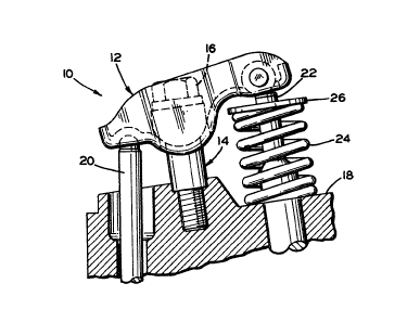
Fig. 1 is a fragmentary, somewhat schematic side view
in elevation of a rocker arm assembly in accordance with the
invention, mounted on an engine shown in cross section;
Fig. 2 is an enlarged view in longitudinal cross section
taken through the rocker arm assembly of Fig. 1, with extreme
positions of the rocker arm shown in dotted lines;
Fig. 3 is a top view of the rocker arm; and
Fig. 4 is a view in transverse cross section taken along
the line 4-4 of Fig. 3.
Referring to the drawings and particularly to Fig. 1, a
rocker arm assembly in accordance with the invention is indi-
cated at 10 and includes an elongate, cold-formed boat-type
rocker arm 12 mounted on a supporting pedestal 14. A suit-
able threaded fastener 16 extends through a bore in the
pedestal 14 and mounts the ass~mbly on a cylinder head 18 of
an engine block. One end of the rocker arm 12 engages the
upper end of a push rod 20 and the other end of the rocker
arm engages the upper end of a valve stem 22. The valve
stem extends upwardly from a val-re (not shown) in the cylin-
der head through a coiled compression spring 24 located there-
around and which is between the cylinder head 1~ and a
retainer ring 26 mounted-on-the valve stem 22.

Referring to Figs. 2 and 3, the rocker arm 12 has an
intermediate recessed area or surface 28 which is of generally
semi-cylindrical shape. The recess 2~ has a central opening


1 322906

30 through which a shank 32 of the pedestal 14 extends. The
pedestal 14 also includes a fulcrum 34 with a lower, down-
wardly-facing surface 36 of a predetermined radius. The
surface 36 engages the recessed surfsce 28 of the rocker
arm and supports the arm for rocking movement.

One end portion of the rocker arm 12 has a concave re-
cess 38 facing downwardly with a lubricating hole 40 communi-
cating with the recess and with the interior of the rocker
arm. The recess 38 engages the upper end of the push rod 20
with the push rod causing the rocking motion of the rocker
arm 12.

The other end portion of the rocker arm 12 has a rec-
tangular end opening 42 which extends between side walls 44
and 46 of the rocker arm and almost to an end wall 47 thereof.
The side walls 44 and 46 have aligned round openings 48 and
50 which receive an axle 52. The axle 52 has flared ends 54
and 56 which are received in flared ends 58 and 60 of the
openings 48 and 50 to prevent longitudinal and rota-
tional movement of the axle 52. A roller 62, which
extends a substantial portion of the distance between
the side walls 44 and 46, is rotatably supported on
the axle 52. A portion of the circumference of the
roller 62 is exposed at the opening 42 and extends
at least partly through the opening 42, as ~hown in
Figs. 2 and 4. The roller 62 is positioned to engage the
end of the valve stem 22~ thus establishing rolling motion

-4-


1 322~06

between the valve stem and the rocker arm 12 rather than
sliding motion between the valve stem and the end of the
rocker arm, as has here~ofore been the case. This rolling
motion results in lower friction during the operation of
the rocker arm and the engine, thereby improving the effi-
ciency of the engine.

In one form, the lower circumferential extremity
of the roller 62 is flush with the lower side edges of the
rectangular opening 42 so that the roller can contact the
end of the valve stem 22 in the same position as if the
lower surface of the rocker arm end were solid instead of
having the opening 42 and the roller 62. This enables the
rocker arm 12 to be substituted for a conventional one
lS without requiring changes in dimensions or positions of any
of the engine components.

Various modifications of the above-described embodiment
of the invention will be apparent to those skilled in the art
and it is to be understood that such modifications can be
made without departing from the scope of the invention,
if they are within the spirit and the tenor of the accom-
panying claims.


5 -
Representative Drawing
A single figure which represents the drawing illustrating the invention.
Administrative Status

For a clearer understanding of the status of the application/patent presented on this page, the site Disclaimer , as well as the definitions for Patent , Administrative Status , Maintenance Fee  and Payment History  should be consulted.

Administrative Status

Title Date
Forecasted Issue Date 1993-10-12
(22) Filed 1989-05-03
(45) Issued 1993-10-12
Deemed Expired 2002-10-15

Abandonment History

There is no abandonment history.

Payment History

Fee Type Anniversary Year Due Date Amount Paid Paid Date
Application Fee $0.00 1989-05-03
Registration of a document - section 124 $0.00 1989-08-03
Maintenance Fee - Patent - Old Act 2 1995-10-12 $100.00 1995-09-14
Maintenance Fee - Patent - Old Act 3 1996-10-14 $100.00 1996-08-15
Maintenance Fee - Patent - Old Act 4 1997-10-14 $100.00 1997-07-09
Maintenance Fee - Patent - Old Act 5 1998-10-13 $150.00 1998-09-23
Maintenance Fee - Patent - Old Act 6 1999-10-12 $150.00 1999-09-20
Maintenance Fee - Patent - Old Act 7 2000-10-12 $150.00 2000-09-20
Owners on Record

Note: Records showing the ownership history in alphabetical order.

Current Owners on Record
HENLEY MANUFACTURING CORPORATION
Past Owners on Record
MILLS, JESSE V.
Past Owners that do not appear in the "Owners on Record" listing will appear in other documentation within the application.
Documents

To view selected files, please enter reCAPTCHA code :


To view images, click a link in the Document Description column. To download the documents, select one or more checkboxes in the first column and then click the "Download Selected in PDF format (Zip Archive)" or the "Download Selected as Single PDF" button.

List of published and non-published patent-specific documents on the CPD .

If you have any difficulty accessing content, you can call the Client Service Centre at 1-866-997-1936 or send them an e-mail at CIPO Client Service Centre.


Document
Description 
Date
(yyyy-mm-dd) 
Number of pages   Size of Image (KB) 
Drawings 1994-03-08 2 51
Claims 1994-03-08 3 83
Abstract 1994-03-08 1 25
Cover Page 1994-03-08 1 12
Description 1994-03-08 4 135
Representative Drawing 2002-02-21 1 16
Prosecution Correspondence 1992-09-08 1 33
Examiner Requisition 1992-05-27 1 60
PCT Correspondence 1993-10-26 1 18
Office Letter 1993-11-09 1 11
Fees 1996-08-15 1 38
Fees 1995-09-14 1 37