Note: Descriptions are shown in the official language in which they were submitted.
1 323090
ULTRASONIC DENSITOMETER DE:VICE AND METHOD
Backaround of the Invention
1. Field of the Invention
The pxesent invention relates to devices which are
used for measuring the den~ity o~ members, such a~
bon~s, and ~ore particularly to devicQ~ which utilize
ultrasonic acou~tic ~ignals to measuro the phy~ical
proper~ies and integrity o~ th- members.
2. DQscription of the Prior Art
Variou~ devices pre~antly exist which may be uced
to measure the phy~ical prop~rties and integrity of a
me~ber such a~ a bons. Non-invasive den~ity measuring
devicea can be used to deter~ino cumulatlve internal
damago cau~od by micro-cru~hing and micro-~racturing
occurring in tho bones of hu~ans or animals such as race
hor~es. Additionally, osteoporo~i , or lo~s of bone
mineralization, detection in humans and its cure or
prevention ar2 increasingly becoming areas Or intense
medical and biological interest. As the average age of
the human population increase~, a greater nu~ber of
patients are developing complications due to rapid
trabecular bone loss.
.
.
'
1 3230qO
U.S. Patent No. 3,847,141 to HooP discloses a
device ~or mea6uring the den3ity of a bone structure,
such as a fin~er bone or heel bone, to monitor the
calcium content thereof. The device includes a pair of
opposed spaced ultrasonic tran~ducers which are held
within a clamping device clamped on the bone being
analyzed. A pulse generator is coupled to one of the
transducers to generate an ultrasonic soundwave which is
directed through the bone to the other transducer. An
electric circuit couples the signals from the receive
transducer back to the pulse generator for retriggering
the pulse generator in response to those signals. The
pulses therefore are produced at a fre~uency
proportional to the transit time that the ultrason1c
wave takes to travel through the bond structure, which
i~ directly proportional to the sp-ed of the sound
through the bone. The speed of sound through a bone has
been found to be proportional to the density of the
bone. Thus the frequency at which the pulse generator
is retriggered is proportional to the density of the
bone.
Another device and method for establishlng, in vivo
the strength Or a bone i8 di~clo~ed in U.S. Patents Nos.
4,361,154 and 4,421,119 to Pratt, Jr. The device
includ-s a launchLng transducer and a receiving
transducer which are connected by a graduated vernier
and which det-rmine the speed of sound through the bone
to determine its strength. The vernier i5 used to
m-asure th- total transit distance between the surfaces
o~ the two transducers.
Leo3 (LQes, S. (1986) Sonic Properties of
Mineralized Tissue, Tis6ue Charlcterization With
Ultrasound, CRC publication 2, pp. 207-226) discusses
various studies involving attenuation and speed of sound
measurements in both cortical and spongy (cancellous or
trabecular) bone. The results o~ these studies reveal a
linear relationship between the WQt sonic velocity and
. .
: : . - ; . .- :
-3- 1 3~30q
wet cortical density, and between the dry sonic velocity
and the-dry cortical density. The transit times of an
acoustic ~ignal through a bone member therefore are
proportional to the bone density. Lan~_n, et al.
t~angton, C.M., Palmer, S.D., and Porter, S.W., (1984)
The Measurement of Broad Band Ultrasonic Attenuation in
Cancellous Bone, En~. Med., 13, 89-91) published the
rQsults of a study of ultra~onic attenuation versus
freguency in the os calcis (heel bon~) that utilized
through tran~mission techniqueo. These author~
suggested that attenuation difforences observed in
different sub~ects were du- to changQs in the ~ineral
contont of the o~ calcis. They al~o suggested that low
frequ~ncy ultrasonic attenuation may be a parameter
u~eful in the diagnosis of osteoporo~i~ or as a
predicter of possible fracture risk.
Summarv of the Invention
The pre~ent invention is summarized in that an
ultrasound densitometer for measuring the phy~ical
properti-~ and integrity o~ a m-mber in vivo, includes:
a tran~mit transducer from whlch acoustic signals having
at l-a~t on speciric frequency component are
tran~mitted through the member and through a material
with known acoustic properties; a receive transducer
which receive~ the acou~tic signals after they have been
transmitted through the member; means connected to said
transducers for determining a member transit time of the
acouotic signals through the member and/or for
determining an absolute attenuation of at least one
individual specific frequency component of the acoustic
s~gnals through the member, and for deter~ining a
material transit time of the acoustic signals through
the material and/or for determining an absolute
attenuation of at least one corre~ponding individual
... . : . . . .
_4_ 1 323090
specific frequency component of the acoustic signals
throuqh- aid material.
Alternatively, the transmit transducer may transmit
acou~tic signal~ through the member, and the receive
transducer receive acoustic signals a~tor they have been
transmitted through the member, the densitometer
including a microprocessor with a databa~e of normal
transit times; means for selecting one of said normal
transit times; means for making a mathemat$cal
comparison o~ said mQmber transit time to the selected
normal transit time; and means ~or relating said
mathematical comparison to the phyJical properties and
integrity of said member. Each of the normal transit
timo- in th- databa~e may b- dependQnt upon the age,
height, weight, race, or sex of the individual being
tested, or on the distance between the transducers, or
on the thickness or size o~ the membert
A primary ob~ect of the invention i8 to provide an
ultra~ound den~itometer devic~ and method for measuring
the physical propertie~ and integrity o~ a member in
vivo by determining the tran~it time o~ ultrasonic
acoustic ~ignal~ through the member quickly, efficiently
and ea~ily.
A second ob~ect o~ the invention i~ to provide an
ultra~ound densitomQter device and method for mea~uring
the phyoical properties and integrity of a me~ber in
vivo by comparing the transit time of ultrasonic
acouetic signals through the member with the transit
tim- o~ tho acou~tic signal~ throuqh a material with
known acou~tic properties.
An additional ob~ect of the invention is to provide
an ultrasound densitometer device and method for
measuring tho physical propertios and integrity of a
member in vivo by determining the absolute attenuation
of specific frequency components of ultrasound acoustic
signals through the member.
. ~ ., , . .
.:
' '' . ' ''
s 1 323090
A further ob~ect of the invention is to provide an
ultrasound densitometer device and method for measuring
the physical properties and integrlty of the member ln
vivo by comparing the absolut- attenuation of specific
frequoncy components of ultrasound acouQtic signals
through the member with the ab~olute attenuation of
corre~ponding frequency components of acoustic signals
through a material of known acoustic propertie~
Another ob~ect of the invention is to provide an
ultra~ound d-nsitometer d-vice and method of measuring
the physical properties and integrity of a member in
vivo by comparing the transit time of ultrasonic
acoustic slgnals through the member with a selected
normal tran~it time select-d from a database of normal
transit times which are dependent upon the age, height,
weight, race, or ~ex of an individual being tested, and
also upon th di~tance betw~en the transducer~ or the
size of the memb-r
Yet an additional ob~-ct of the invention is to
provide ultra~ound densitometer device and method for
mea~uring the phy~ical prop~rtie~ and integrity of a
bone member in vivo which can display the density of the
m-mber and a digital compo~ito member waveform of the
rQceived acou~tic signal on a digital display
Yet an additional ob~ect of ths invention i9 to
provid~ an ultrasound densitometor device and method for
mea~uring the physical properties and integrity of a
member ln vivo which device has a transmit and a receive
tran~ducer which can each include an array of a
plurality of olements, whereby the acoustic signals
received by on- or more of the receivo elem-nt~ may be
analyzed to detQrmin- a relative position with r-sp-ct
to the member of each of the acoustic s$gnals received
by the receive lements
Other ob~ects, features and advantages of the
invontion will be apparent from the following detailed
de~cription taken in con~unction with the accompanying
.: ..
-6- 1 323090
drawlngs wherein a preferred embodiment of the invention
has been selected for exemplification.
Brief Descri~tion of the Drawinqs
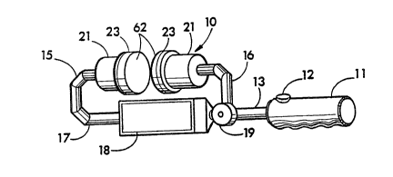
Fig. 1 is a perspective view of the ultrasound
densitometer device con~tructed in accordance with the
present invention.
Fig. 2 is a perspective view of an acoustic
coupler, ~wo of which are shown in Fig. 1.
Fig. 3 is a front view of a tran~ducer face from which
acoustic signals are transmitted or by which acoustic
signals are received, the fac0 of the other transducer
being the mirror image thereof.
Fig. 4 is a schematic block diagram view of the
circuitry of the ultrasound den~itometer device
constructed in accordance with the present invention.
Fig. 5 illustrates the method of sampling a received
waveform used by the circuit of Fig. 4.
F$g. 6 i8 a schomatic block diagram view of the
circuitry of an alternative embodiment of an ultrasound
den~itometer constructed in accordance with the pr~sent
invention.
Fig. 7 i~ a sample of an actual ultrasonic pulse and
responsQ fro~ an ultrasonic densitometer according to the
pr~sent invention.
Fig. 8 i~ a sampl~ plot of relative ultrasound pulse
intensity over frequency rangQ.
Fig. 9 i~ a graph in frQquency domain illustrating
the shi~t in alternation versu~ fr~quency characteristic
of a measured ob~ect as compared to reference.
Descri~tion of the Preferred Embodiment
Referring more particularly to the drawings, wherein
like numbers r~fsr to like parts, Fig. 1 ~hows a portable
-, 1 3230qO
ultra~ound densitometer lo for measuring the physical
propertie~ and integrity of a member, such as a bone, in
vivo. The densitometer 10 as shown in Fig. 1 includes a
handle 11 with actuator button 12. Extending linearly
from the handle 11 is a connection rod 13. The
densitometer 10 also includes a fixed arm 15 and an
ad~ustable arm 16. The fixed arm 15 preferably i9 formed
continuously with the connection rod 13, and therefore is
connected to an end 17 of the connection rod 13. The
adjustable arm 16 i8 slidably mounted on the connection
rod 13 between the handle 11 and a digital display 18
mounted on the rod 13. The knob 19 may be turned 80 as to
be locked or unlocked to allow the ad~ustable arm 16 to be
slid along th- connection rod 13 80 that the distance
between the arm~ 15 and 16 may be ad~u~ted.
Connected at the end o~ the rixed arm 15 is a first
(left) transducer 21 and at the end of the adjustable arm
1~ i8 a second (right) transducer 21. A~ shown in Figs. 1
and 2, each of the transducer~ 21 has mounted on it a
respective compliant acoustic coupler 23 to acoustically
couplo the tr~nsducer to the ob~ect being tested. The
acou~tic coupl-r 23 includ-s a pla~tic ring 24 and
attached pad 26 ~ormed of urothane or other compliant
material. Flgur- 3 show~ a face 28 of the first (left)
tran~duc-r 21 which io normally hidden behind the
compliant pad 26 of th- acoustic coupler 23. The
tran~duc-r ~ac- 28 normally abuts against the inner
surfacQ 29 o~ th- pad 26 shown in Fig. 2. The transducer
fac- 28 ~hown in Fig. 3 includes an array of twelve
transducer elements labeled a-l. Tho second (right)
tran~ducer 21 includes a face 28 which is the mirror image
of that shown in Fig. 3.
Figure 4 generally shows in schematic fashion the
electronic circuitry 31 of the densitometer 10, which is
physically contained in the housing of the digital display
18. An ob~ect 32 is placed between the two transducers 21
so that acoustic signals may be transmitted through the
. " , ~:, .. . .
:: . . , ~: ~: ... . .
-8- 1 323090
ob~ect This ob~ect 32 represents a member, ~uch as a
bone, or some material with known acoustic properties such
as distilled water or a neoprene reference block As
shown in the embodiment illustrated in Fig 4, the
leftmost transducer 21 is a transmit transducer and the
rightmost transducer 21 a receive transducer In fact
though, either or both of the transducers 21 may be a
transmit and/or recei~e transducer ~he transmit and
receive transducers 21 of the circuit of Fig 4 are
connected by element select signals 36 and 37 to a
microprocessor 38 The microprocessor 38 is programmed to
determine which one of the respective pairs of transducer
elements a through 1 are to b- transmitting and receiving
at any one time This selection is accomplished by the
el-m nt selec~ signal lines 36 and 37, which may be either
multiple signal lines or a serial data line to transmit
th- n--ded s-l-ction data to the tran~ducers 21 The
microproce~or 38 is al~o connected by a data and address
bu~ 40 to the digital display 18, a digital signal
proces~or 41, a sampling analog to digital converter 42,
and a ~t of external timers 43 The microprocessor 38
ha- ~on board" electrically programmable non-volatile
random access m mory ~NVRAM) and, perhaps a~ woll,
conventional RAM memory, and controls the operations of
th- d-n~itom-tsr 10 Th dlgital signal procQssor 41 has
~on board" r-ad-only memory ~ROM) and performs many of the
math-matical functions carried out by the densitometer lo
und-r th- control of the microprocessor 38 The digital
signal proce~or 41 specifically includes the capability
to perform di~crete Fourier transforms, as is commercially-
available in integrated circuit form presently, 80 as to
be able to convert received waveform signals from the time
domain to the frequency domain The microprocessor 38 and
digital signal procQssor 41 are interconnected also by the
control signals 45 and 4~ so that the microprocessor 38
can maintain control over the operations of the digital
signal processor 41 and receive status information back
,. . ; .
. .
, ................. . . .
-
.
-9- 1 323090
Together the microprocessor 38 and the digital signal
processor-41 control the electrical circuit 31 80 that the
densitometer 10 can carry out its operations, which will
be discussed below. An auditory feedback mechanism 48,
~uch as an audio speaker, can be connected to the
microprocessor 38 through an output signal 49.
The external timer 43 provides a series of clock
si~nals 51 and 52 to the A/D converter 42 to provide time
information to the A/D converter 42 80 that it will sample
at timed intervals electrical signals which it receives
ultimately ~rom the transmit transducer, in accordance
with the program in the microprocessor 38 and the digital
signal processor 41. The external timer 43 also create a
cloc~ signal 53 to an excitation amplifier 55. Timed
pulses are generated by the timer 43 and sent through the
signal line 53 to the amplifier 55 to be ampli~ied and
directed to the transmit transducer 21 through the signal
line 56. The transmit transducer 21 converts the
amplified pulse into an acoustic signal which i8
transmitted through the ob~ect or material 32 to be
rec-ived by the receive transducer 21 which converts the
acoustic ~ignal back to an lectrical signal. The
electrical ~ignal i8 direct-d through output signal 57 to
a receiver amplifier 59 which amplifies the electrical
signal.
The excitation amplifier circuit 55 is preferably a
digitally controllable circuit designed to create a pulsed
output. Tho amplif~cation of the pulse can be digitally
controlled in ~teps from one to ninety-nine. In this way,
the pulse can be repetitively increased in amplitude under
digital control until a received pulse of appropriate
amplitude is received at the receiver/amplifier circuit
59, wh~re tho gain is also digitally ad~ustable.
Connected to the receiver amplifier circuit 59 and
integral therewith is a digitally controllable automatic
gain control circuit~which optimizes the sensitivity of
the receive transd~cer 21 and the amplifer circuit 59 to
~ . . . . .................... . .~. :
, ~ ;., ~ . , :, ~
-lO- 1 323090
received acoustic signals The microprocessor 38 is
connected~to the amplifier circuit and automatic gain
control 59 through signal line 60 to regulate the
amplification of the amplifier circuit and gain control
59 The amplified electric signals are directed through
lead 61 to the A/D converter 42 which samples those
signals at timed intervals The A/D converter 42
therefore in effect samples the received acoustic
signals As a serie~ of substantially identical acoustic
signals are received by the rec-ive transducer 21, the A/D
converter 42 progres~ively sample~ an incremental portion
of each succ-osive ~ignal waveform The microprocessor 38
is programmed so that tho~e portion~ are combined to form
a digital composite waveform which i- nearly identical to
a single waveform This digitalized waveform may be
di~played on the digital dlsplay 18, or processed for
numerical analysis by the digital ~ignal processor 41
The densitometer con~tructed in accordance with Figs
1-4 can be operated in one or mor- of oeveral distinct
method~ to meaiure the physical properties of th- member,
such as integrity or density The different methods, as
de~cribed in further detail below, depend both on the
softwar- programming the operation of the mlcroprocessor
34 as well a~ the instructions given to the cliniclan as
to how to U~Q th- den~itometer The different methods of
use may all be programmed into a single unit, in which
ca~e a user-~-l-ctable switch may be provided to select
the mod~ of op-ration, or a given densitometer could be
constructed to be~dedicated to a single mode of use In
any event, for the method of use of the densitometer to
mea~ure the physical properties of a member to be fully
understood, it is first necessary to understand the
internal operation of the densitometer itself
In any of its methods of u8e, the densitometer is
intended to be placed at some point in the proces~ on the
member whose properties are being measured This is done
by placing the transducers 21 on the oppos$te sides of the
. . . . - , - ., . -
.. . . .
.. ..
.. ..
-11- 1 3230qO
member To accomplish this, the knob 19 is loosened to
allow the-ad~ustable arm 16 to be moved so that the
transducers 21 can be placed on opposite sides of the
member, such as the heel of a human patient The outside
surfaces of the pads 26 can be placed against the heel of
the sub~Qct with an ultrasound gel 35 or other coupling
material placed between the pads 26 and sub~ect 32 to
allow for improved transmission o~ the acoustic signals
between the member 32 and transducers 21 once the
transducers 21 are properly placed on the member, the knob
19 may be tightened to hold the ad~ustable arm 16 in
plac-, with th- transducer~ 21 in spaced relation to each
other with the member 32 thereb-tween The actuator
button 12 may then bo presoed 80 that acoustic signals
will be transmitted through the member 32 to be received
by the receive transducer 21 The electronic circuit of
Fig 4 receives the electrlcal signals from the receive
tran~ducer 21, and sample~ and process-s thesQ signals to
obtain information on th- physical properties and
integrity of the member 32 in vivo The microprocessor 38
i~ programmed to indicat- on the digital display 18 ~hen
this information gath-ring procQss i8 CompletQ.
Alt-rnatively, th- information may b- displayed on the
digital di~play 18 when th- information gathering process
i8 completed For example, the transit time of the
acoustic ~ignals through the member 32 could simply be
display-d on th- digital display 18
Con~idering in detail the operation of the circuitry
of Fig 4, th- general concept is that the circuitry is
dQsigned to create an ultrasonic pulse which travels from
transmit transducer 21 through the sub~ect 32 and iB then
received by the receive transducer 21 The circuitry is
designed to both determine the transit time of the pulse
through the member 32, to ascertain the attenuation of the
pulsQ through the member 32, and to be able to reconstruct
a digital representation of the waveform of the pulse
after it has passed through the member 32, so that it may
, .; , . ~ . ," . ~ . . . .... . .
,. .. , ~ , : , ......... . .; . .
. . ~ ,:, , : . , .. .:..... ..
-12- 1 32 3 090
be analyzed to determine the attenuation at selected
freguencie~ To accomplish all of these ob~ectives, the
circuitry of Fig 4 operates under the control of the
microproce3sor 38 The microprocessor 38 selectively
sQlects, through th~ elem-nt select ~ignal llnes 36, a
corresponding pair or a group of the elements a through 1
on the face of each of the transducer~ 21 The
corresponding elQments on each transducer are selected
simultaneously while the remaining elements on the face of
each transducer are inactive With a given element, say
for example eloment a selected, the microprocessor then
causes th- external timer 43 to emit a pulse on signal
line 53 to the excitation amplifier circuit 55 The
output of the excitation amplifier 55 travels along ~ignal
line 56 to element a o~ the transmit tran~ducer 21, which
th-r-upon emits the ultrasonic pulse The corresponding
elem-nt a on the receiv- transducer 21 rQceives the pulse
and pre~ent~ its output on th- signal line S~ to the
amplifler circuit 59 What is desired as an output of the
A/D converter 42 is a digital representation of the analog
waveform which is the output of the single transducer
elem-nt which ha~ beon selected Unfortunately, "real
time" sampling A/D conv-rters which can operate rapidly
enough to sample a wav-~orm at ultrasonic frequencies are
r-lativ-ly expen~iv- Ther-fore it i8 preferred that the
A/D conv-rt-r 42 b- an "eguivalent time" sampling ~/D
converter By "equivalent time" sampling, it is meant
that the A/D converter 42 samples the output of the
tran~ducer during a narrow time period after any given
ultrasonic pulse The general concept is illustrated in
Fig S The ty~ical waveform of a single pulse received
by the receive transducer 21 and imposed on the signal
lin- 57 i~ indicated by a function "~" The ~ame pulse is
repetitively received as an excitation pulse i5
repetitively launched The received pul~e is sampled at a
sequence of time periods labeled to-tlo In other
- . , , ~ . ,~ , .
- , ~ . . : .
.
-13- 1 32 30q0
words, rather than trying to do a real-time analog to
digital conversion of the signal f, the signal is sampled
during individual fixed time periods to-tlo aftor the
transmit pulse is imposed, the analog value during each
time period is converted to a dlgital function, and that
data is stored Thus the total analog wave form response
can be recreated from the individual digital values
created dur$ng each time period t, with the overall
fidelity of the recreation of the wave form dependent on
the number of time periods t which are sampled The
sampling is not accomplished during a single real time
puls- from th- receive tran~ducer 21 Instead, a series
o~ pul-e- ar- emitted from the transmit tran~ducer 21
The xt-rnal timer is constructed to provid- signals to
th- sampling A/D converter 42 along signal lin-s 51 and 52
such that th- analog value sampled at time period to
wh-n th- rirst pulse i9 applied to a giv-n transducer
l-ment, then at time tl during the second pulse, time
t2 during the third pulse, etc until all the time
periods are sampled Only after the compl-te waveform has
been sampled for each lem-nt i8 th- next element, i e
leaent b, selected The output from the A/D converter 42
is provided both to the microprocessor 38 and to the
signal proc-osor 41 Thus the digital output values
r-pre~enting th~ complex waveform f of Fig 5 can be
proces--d by th- signal proce~sor 41 arter they are
compll-d ~or ach transducer element The waveform can
then b- an~lyz-d for tlme delay or attenuation for any
giv-n frequency component with respect to the
charact-ri~tic of the transmitted ultrasonic pulse The
proces6 is then repeated for the other elements until all
elements have been utilized to transmit a serie~ of pulses
sufficient to create digital data repre3enting the
waveform which was received at the receive transducer
array 21 It i8 this data which may then be utilized in a
variety of methods rOr determining the physical properties
of the member, and determining on the manner in which the
~, . ~ . ................................. : ,,
.; ~ . .. ..
~' ' . ~ .
-14- 1 3230qO
donsitometer i8 being utilized, and the data being sought,
the appropriate output can be provided from either the
microprocessor 38 or the signal processor 41 through the
digital display 18.
~ ecause the ultrasonic pulsing and sampling can be
performed so rapidly, at least in human terms, the process
of creating a sampled ultrasonic received pulse can
optionally be repeated several times to reduce noise by
signal averaging. If this option is to be implemented,
the process of repetitively launching ultrasonic pulses
and sampling the received waveform as illustrated in Fig.
5 is repeated one or more times for each element in the
array before proceeding to the next element. Then the
sampled waveforms thus produced can be dlgitally averaged
to produce a composite waveforc that will have a le6ser
random noise component than any s$ngle sampled waveform.
The number of repetitions necessary to sufficiQntly reduce
noisQ can be determined by testing in a fashion known to
one skill-d in the art.
Having thus reviewed the internal operation of the
densitometer of Pigs. 1-4, it i8 now possible to
under~tand the method~ Or use o~ the densitometer to
measure the physical properties o~ the member. The first
method o~ u~e involves measuring tran~it time of an
ultrasonic pu180 through a sub~ect and comparing that time
to the time an ultrasonlc pulse require~ to travel an
equal dl-tance ~n a substance of known acoustic properties
such as water. To use the densitometer in this procedure,
the ad~u~table arm 16 is ad~usted until the member of the
sub~ect,~such as the heel, is clamped between the
transducer~ 21. Then the knob 19 is tightened to fix the
ad~ustable arm in place. The actuator button 12 is then
pressed to initiate a pulse and measurement. Next the
densitometer is removed from the ub~ect while keeping the
knob 19 tight so that the distance between the transducers
21 remain~ the same. The-device 10 is then placed about
or immersed in a standard material 32 with known acoustic
'~ '.', ' .
-15- l 323090
proporties, such ~g by immersion in a bath of di~tilled
water The actuator button 12 i8 pressed again 80 that
acoustic signals are transmitted from the transmit
transducer 21 through the material 32 to the receive
transducer 21 While it is advantageous to utilize the
whole array of elements a through l ~or the measurement of
the member, it may only be necessary to use a single pair
of elements for the measurement through the standard
a~suming only that the standard is homogeneous, unlike the
member The signal profiles received by the two
measurements are then analyzed by the microprocessor 38
and the signal processor 41 This analysi~ can be
directed both to the comparative time of transit of the
pulse through the sub~ect as compared to the standard and
to the characteristico of th- wave~orm in ~reguency
re~pon~e and attenuation through the sub~-ct as compared
to the standard
Thus in this method the densitometer may determine
the physical propertios and integrity of the member 32 by
both or either of two forms of analy~is The densitometer
may compare the translt time of the acoustic signals
through the member wlth the transmit time of the acoustic
signal~ through tho mat-rial of known acou-tic properties,
and/or th- devlc- lO may compare th- attenuation as a
function o~ fr gu-ncy of th- broadband acoustic signals
through the ~ember 32 with the absolute attenuation of
corre-ponding ~p-cific frequency components of the
acoustic ~ignal~ through the material of known acoustic
properti-~ Th- "attenuation" of an acoustic ~ignal
through a sub~tance is the dimunition of the ultrasonic
waveform from the propogation through either the subject
or the standard The theory and experiments using both of
these methods are presented and discussed in Rossman,
P J , Measurement~ of Ultrasonic Velocity and Attenuation
In The Human Os Calcis and Their Relationships to Photon
Absorptiometry Bone Mineral Measurement~ (1987) ta thesis
submitted in partial fulfillment of the requirements for
, . . . ~ , . . .... . .
- , , , , ~ : :
.. . ~: . ..
-16- 1 32 3 Oq
the degree of Master o~ Science at the University of
Wisconsin-Madison). Tests have indicated that there
exists a linear relationship between ultrasonlc
attenuation (measured in decibels) ~db)) at speci~ic
freguencies, and thosQ frequencies. The ~lope (d~/MHz) of
th- linear relationship, referred to a~ the broadband
ultrasonic attenuation, is dependent upon the physical
properties and integrity o~ the substance beinq tested.
With a bone, the slope of the linear relationship would be
dependent upon the bone mineral density. Thus broadband
ultrasonic attenuation through a bone is a parameter
directly related to the guality of th- cancellous bone
matrix.
The microprocessor 38 may therefore be programmed 80
that the device determines the phy~ical properties and
integrity of the member by comparing either relative
transit times and/or relativQ broadband ultrasonic
attenuation through the member and a material o~ known
acoustic properties. When comparing the transit times,
the microproces~or 38 may be programmed most simply so
that the electronics, having received the acoustic s$gnals
after they have been transmitted through the member,
determines th- "momber" transit tim- o~ tho~e acoustic
signals through tho member, and after the acoustic signals
have b-en tran-mitted through th- material of known
acou~tic prop-rtle-, determinos the "material" transit
time of the acou~tic signal~ through the material. These
tim- period~ may be measured mo~t simply by counting the
number o~ clock pulses o~ known ~reguency emitted by the
timer 43 between the time o~ launching the pulse and the
sen~ing of the received pulse at the A/D converter 42.
The microproce~sor 38 then makes a mathematical "time"
compari~on o~ the member transit time to the material
transit time and then relate~ that mathematical time
comparison to the physical properties and integrity of the
member. The mathematical time comparison may be made by
either determining a difference between the member transit
,
1 323090
time and the mater~al transit time, or by determlning a
ratio between the member transit time and the material
transit time
As a second method of using the dQnsitometer, it may
also determine the physical properties and integrity of
the member 32 by determining and comparing the absolute
attenuation of the broadband frequency components of the
acoustic signals through the member wlthout reference to a
material having known acoustic properties Using this
method, the comparison of velocity to a standard is not
necessary and absolute transit time of the pulse need not
be calculated since it is attenuation that is measured
In such a mode, it i8 pre~erable that the transmit
tran~ducer 21 transmits an acou-tic signal which has a
broad rang of frequency components, ~uch a~ a simple
ultrasonic pulse In any case, the acoustic signal should
have at least one speci~lc fr-qu-ncy component
In this attenuation comparison mod~, the
microprocessor 38 i~ programmed 80 that after the receive
tran~ducer 21 receives the acou~tic signal~ tran~mitted
~through the bone member 32, it determineo the absolute
att-nuation through the member 32 of the frequency
component sp-ctrum of the acou~tic signal~ It i8 to
facilitate th- mea~urement of attenuation that the
excitation amplifi-r circuit 55 And the receiver amplifier
59 have ampllfic~tion levels which may be digitally
controlled By ~uccessively varying the gain of the
amplifiers 55 and 59 on ~ucce~sive pulses, the circuit of
Fig 4 can determine what level ot gain is nece~sary to
place th- peak Or the received wavefor~ at a proper
voltage level r This gain 18, o~ course, a function of the
level of attenuation of the acoustic pulse during transit
through the me~bsr 32 After the receive transducer 21
receives acoustlc signals, microproce~or 38 in
con~unction with the signal processor 41 determines the
absolute attenuation of individual specific freguency
components of the received acoustic signal transmitted
- ~ ~
~ . . - . . :
-18- 1 323090
through the material. The digital signal processor 41
then make- mathemAt~cal "attenuation" comparisons of the
corresponding individual specific frequency components
through the member. A set of mathematical attenuation
comparisons between corresponding freguency components may
be thereby o~tained, one comparison for each frequency
component compared. The manner in which the attenuation
functions with respect to frequency can thus be derlved.
The microprocessor 38 and digital ~ignal processor 41 then
relate that function to the physical properties and
integrity of the member.
Shown in Flg. 7 is a sample broadband ultrasonic
pulse and a typical received waveform. To achieve an
ultrasonic signal that i8 very broad in the ~requency
domain, i.e., a broadband transmitted signal, an
l-ctronic pul~- such as indlcat-d at 70 is applied to the
s-l-cted ultra~onic transduc-r in th transmit array 21
whlch thon resonate~ with a broadband ultrasonic emission.
The r-c-ived ~ignal, ~uch as indicated at 72 in Fig. 7 in
a time domain ~ignal plot, is then processed by discrete
Fourier tran~form analysis oo that it i8 converted to the
fr-gu-ncy domain. Shown in Fig. 8 i8 a pair Or plots of
~ampl~ recQiv-d lgnal~, in fr-quency domain plots,
showing the ~hlft in received ~ignal intenoity as a
function of fr-gu-ncy between a r-fer-nce ob~ect and a
plug of neopren- placed in the in~trument. Fig. 9
illustrate~ a similar comparison, with Fig. 8 using
relative attenuation in the vertical dimen~ion and Fig. 9
u-ing ab~olute power of the received signal. Both
repre~entation~ illustrate the difference in relative
intensities as a function of frequency illustrating how
broadband ultrasonic attonuation varies from ob~ect to
ob~ect. The actual value calculated, broadband ultrasonic
attenuation, i~ calculated by first comparing the received
signal against the reference signal, then performing the
discrete Fourier transform to convert to frequency domain,
then performing a linear regres~ion of the difference in
. . - .. ,~ , ~
,
-
,: , .1
.
-19- 1 323090
attenuation slope to derive broadband ultrasonic
attenuation.
The mathematics of the discrete ~ourier transform
are such that another parameter related to bone member
density may be calculated in addition to, or in
substitution for, attenuation. When the dlscrete Fourier
trans~orm is performed of the time-domain signal, the
solution for each point includes a real member component
and an imaginary member component. The values graphed in
Figs. 8 and 9 are the amplitude of the received pulse as
determined from this discrete Fourier tran~form by taking
th- sguare root of th- sum of the sguares of the real
compon-nt and the imaginary component. The phase angle of
the change in phas- of the ultrasonic pulse as it passed
through the me~mber can be calculated by taking the
arctangent o~ th- ratio of the imaginary to the real
components. This phasQ angle value is also calculated to
bon- m mber density.
The microprocessor 38 may al~o be programmed so that
th- densitom tQr simultaneously performs both functions,
i.e. determine~ both transit time and absoluto attenuation
of the transmitted acou~tic signals, first through the
memb-r and th-n through the material with known acoustic
propQrtie~. The donsitometer may then both derive the
broadband ultra-onlc attenuation ~unction and make a
mathematical time compari~on of the member transit time to
the materlal transit time. The microproces~or 38 and
digital ~ignal processor 41 then relate both the time
r compariBon along with the attenuation function to the
physical proporties and integrity, or density of the
member 32.
In yet another pos~ible mode of operation the
microprocessor 38 may be programmed 80 that the
densitometer 10 operates in a mode whereby the need for
calculating either the relative transit time or the
attenuation of the acoustic signals through a material of
known acoustic properties is eliminated. In order to
. : - , . . . ~ .:. .
- . .
,~
.. . .
-20- 1 323090
operate in ~uch a mode, the microprocessor 38 would
include a--database of normal absolute transit times which
are based upon such factor~ as the age, height, weight,
race or the sex of the individual being tested as well as
the distance between the transducers or the thickness or
size of the member. This database of normal transit times
can be stored in the non-volatile memory or could be
stored in other media. When testing an individual in this
mode, the relevant factors ~or the individual are placed
into the microprocessor 38 to select the pertinent normal
transit tlm based on thosQ ~actors. The transducers 21
are placed on the bone member being tested as described
above. When the actuator button 12 is pressed, the
acoustic slgnals are transmitted through the momber 32.
The receive transducQr 21 receive~ those signals a~ter
they have been tran~mitted through the member, and the
electronics 31 then determine the "membQr" transit time of
the acoustic signals through the member. The
microprocessor 38 and digital signal processor 41 then
make a mathema~ical comparison of the measured member
transit time to the selected database normal transit time,
and relate th- mathematical time comparison to the
physical propertie~ and integrity, or density of the
member, which i8 dl8played.
As an alternative output o~ the densitometer of the
present lnvention, the digital display 18 could also
include a display corresponding to the pattern of the
array o~ Qlements on the face of the transducer 21 as seen
in Fig. 3. This display could then display, ~or each
element a through 1, a gray scale image proportional to
the paramoter, i.e. transit time or attenuation, being
m a~ured. This image may provide a visual indication to
an experienced clinician a~ to the physical properties of
the member present in the patient.
Shown in Fig. 6 is a circuit schematic for an
alternative embodiment o~ an ultrasonic densitometer
constructed in accordance with the present invention. In
~ '~ .' ~ ' ; ' !
',`~ `
:-:`
-21- 1 323090
the circuit of Fig. 6, parts having similar structure and
function to their corresponding parts in Fig. 4 are
indicated with similar reference numeral~.
The embodiment of Fig. 6 is intended to functLon with
only a single transducer array 21 which function~ both as
the transmit and the receive transducer array. An
optional reflecting surface 64 may be placed on the
opposite side of the member 32 from the transducer array
21. A digitally controlled multiple pole ~witch 66,
preferably an electronic switch rather than a physical
ono, connectJ the input to and output from the elements of
the transducer array 21 selectively either to tho
excitation amplifier 55 or to the controllable gain
receiver/amplifier circuit 59. The switch 66 is connected
by a switch control line 68 to an output of the
microproces~or 38.
In the operation Or the circult o~ Fig. 6, it
functions in most respects like the circuit Or Fig. 4, so
only the differencQs need be discussed. During the
launching of an ultrasonic pulse, the microprocessor 38
causes a signal to appear on thQ switch control line 68 to
cause the switch 66 to connect the output of the
excitatlon amplifier 55 to the ~elected element in the
tran~ducer array 21. Following completlon of the
launching of the pul~Q~ the microprocessor 38 changes the
signal on the owitch control line 68 to operate the switch
66 to connect th~ selected element or elements as an input
to the amplifier 59. Meanwhile, the pulse propogates
through the member 32. As the pulse transits through the
member, reflective pulses will be generated as the pulse
crosses interfaces of differing materials in the member
and, in particular, as the pulse exits the member into the
air at the opposlte sidQ of the member. If the transition
from the member to air does not produce a sufficient
reflective pulse, the reflecting surface 64 can be placed
against the opposite side of the member to provide an
enhanced reflected pulse.
1 323090
-22-
Tho embodiment of Fig. 6 can thus be used to analyze
the physical properties and integrity of a member using
only one transducer 21. All of the methods described
above for such measurements may be used equally
effectively with this ver ion of the device. The transit
time of the pulse through the member can be measured
simply by measuring the time period until receipt of the
reflected pulse, and then simply dividing by two. This
time period can be compared to the transit time, over a
similar di~tance, through a standard medium such as
water. The time period for receipt o~ the reflected pulse
could also be ~imply compared to standard values for age,
sex, etc. Attenuation measurements to detect differential
freguency aea~urement can be directly made on the
reflected pul8e. If no reflecting ~urface 64 i9 u~ed, and
it is de~ired to determine absolute transit time, the
thicknese Or the member or sample can be measured.
The u8e o~ the multi-element ultrasonic transducer
array for the transducers 21, as illustrated in Fig. 3,
enables another advantageous feature of the instru~ent of
Figs. 1-9. Using prior art densitometers it was often
necessary to precisely position the instrument relative to
the body member of the patient being measured to have
userul results. The difficulty arises bQcaus- of
het-rogeniti-s in th- bone ma~s and structure of actual
body mombers. A measursment taken at one location of
density m~y be signiricantly different fro~ a measurement
taken close by. ThereforQ prior art instruments fixed
the body. member precisely 80 that the measurement could be
taken at the precise location each time.
The use of the ultrasonic transducer array obviates
the need for thi~ precise po~itioning. Using the
instrument of Figs. 1-9, the instrument performs a pulse
and response, performs the discrete Fourier transform, and
generates a value for bone ultra~onic attenuation for each
pair of transducer elements a through 1. Then the
microprocessor 38 analyses the resulting array of bone
- - -
, ..,: ~ :
,. . , .~ . .~
.~ , , , .: . : :
,
. . .. .
-23- 1 323090
ultrasonic density measurements to reproducibly identify
the same Eegion of interest each tlme. In other words,
since the physical array of transducero is large enough to
reliably cover at least the one common region of interest
each time, the measurement i8 localized at the same locus
each time by electrically ~electing the proper location
for the mea~urement from among the locations measured by
the array. The in~trument of Fig. 1-9 i8 conveniently
used by mQasuring the density of the 08 calcis as measured
through the heel of a human patient. When used in this
location, it has been found that a region of interest in
the oo calcis can be located reliably and repeatedly based
on the comparison~ o~ bone ultrasonic attenuation at the
points in the array. The region of intereat in the 08
calcis i~ identified as a local or relative minimum in
bone ultrasonic attenuation and/or velocity closely
ad~acent the region of highest attenuation values in the
body member. Thus repetitive measurements of the bone
ultrasonic attenuation value at this same region of
intere~t can be reproducibly taken even though the
den~itometer in~trument 10 is only generally positioned at
the same location for each succes~ivQ measurement.
Thi~ technique ot u~ing a multiple element array to
avoid po~itlon crlticality io applicablo to other
t-chniques other than the determination of broadband
ultra~onic att-nuation as described here. The concept o~
u~ing an array and comparing the array of results to
determine mea~urement locus would be equally applicable to
measur-ments taken of member-density based on speed o~
sound tran~it time, other measurements of attenuation or
on the calculation of phase angle discus3ed above. The
use of such a multiple-element array, with automated
selection o~ one elemen~ in the region of interest, can
also be applied to other measurement techniques useful for
generating parameters related to bone member density, such
as measuring speed changes in the transmitted pulse such
as suggested in U.S. Patent 4,361,154 to Pratt, or
- . : ~ . ,.. ; .
,
.... .. .
,,
.
': ;: :. :
-24- 1 323090
measuring the frequency of a "sing-around" self-triggering
pulse as suggested in U S Patent 3,847,141 to Hoop The
concept which permits the position independence feature is
that of an array of mea~urements generating an array of
data points from which a reglon of intQrest i~ selected by
a reproducible criterion or several criteria The number
of elements in the array also clearly can be varied with a
larger number of elements re~ulting in a greater accuracy
in identifying the same region of interest
In thi~ way, the ultrasound densitometer of the
pr-s-nt inv-ntion provides a devic- capable of rapid and
fficient determination Or the physical properties of a
m-mber in vivo without the use of radiation Because the
den-itom ter i~ constructed to oporate under the control
of th- microprocs~sor 38, it can b- programmed to operate
in one of oeveral mode~, as discussed above This allows
both for flexibility to clinical goal~ as well as
efficient U8- of the device
It is specifically intended that the preoent
invention not be specifically limited to the embodiments
and illu~trations contained herein, but embraces all such
modified forms thereof as come within the scope of the
following claims
... . .. . .