Note: Descriptions are shown in the official language in which they were submitted.
r~ 9
APPARATUS AND METHOD FOR THE
CONTINUOUS EXTRUSION AND PARTIAL
DELIQUEFACTION OF OLEAGINOUS MATERIALS
Backqround of the In~ention
Field of the Invention
This invention relates to an apparatus for the extrusion
of oleaginous plant materials, or oilseeds, as a preparatory
step to solvent extraction of oil from the oilseeds. In
particular, this inventio~ relates to an extruder having
means for draining oil liberated from the plant material
during the extrusion of the material.
A standard method of obtaining oil from oleaginous
materials such as oilseeds is solvent extraction.
Extrusion is sometimes used as a preparatory step
to improve the properties of the material which is treated
in large-scale commercial solvent extraction systems. For
example, oleaginous plant materials like rice bran, which
are troublesome in solvent extraction because of their fine
particulate nature which retards the flow of solvent
7 9
2 ~7768-43
through the material thereby reduclng the efflciency of the
extractor, are converted by extruslon lnto porous collets whlch
allow for much faster flow of solvent through the materlal. Other
oleaginous plant materlals, such as soybean, are often flaked
prlor to solvent extractlon, but the flakes have a low bulk den-
slty and tend to fall apart during solvent extractlon, preventlng
an ade~uate drainage of solvent from the sollds resldue (marc)
leaving the extractor. Extruslon converts the flakes lnto porous
collets havlng greater bulk denslty than flakes, whlch allows for
an lncrease of capaclty flowlng through the extractor wlthout
changlng the bed depth or extractlon tlme wlthln the extractor.
The collets have greater strength than flakes and do not fall
apart so easlly, whlch allows the marc to draln better before lt
exlts the extractor.
~ ome oleaglnous plant materlals contaln hlgh levels of
oll, or fat, as, for example, peanuts, safflower, rapeseed or
canola, and copra. These materlals are typlcally crushed ln screw
presses as a flrst step, to help rupture the cells contalnlng the
oll and to remove from the materlal a slgnlflcant portlon of the
oll. The partlally de-olled resldue ls then cracked, or flaked,
and sent dlrectly to a solvent extractor, or lt ls processed
through an extruder flrst before golng to the extractor to attaln
larger, flrmer, collets and/or to attaln hlgher bulk densltles.
/ 9
3 27768-43
Extruslon has been very effectlve ln lmprovlng the sol-
vent extractabillty of many oleaginous plant materlals and ls well
establlshed ln the preparatlon of soybean, rlce bran, cottonseed,
and pre-pressed canola, sunflower and other oilseeds. There are,
however, some problems ln the extruslon of some oleaglnous plant
materials.
One problem with present extruders is that, lf the oil
or fat level of the materlal golng into the extruder ls above
about 30% by welght, some of the oll is llberated wlthln the
extruder. This interrupts the steady-state operatlon of the ex-
truder by creatlng pockets of free oil randomly spaced within the
~ matrix of solld resldue. The pockets of free oll exlt the extru-
`~ der at hlgh veloclty and interrupt the flow of collets. This also
causes an undeslrable loss of oll, the oil belng the prlnclpal
product sought during solvent extraction.
Another problem with extruders currently used ln the
oilseed lndustry is related to the low bulk denslty of the flaked
material enterlng the extruder. When extruders are used to pro-
cess materials besldes ollseeds, for example, pet foods, the
material being fed into the extruder ls granular and at a rela-
tively hlgh bulk denslty, around forty pounds per cubic foot. For
the treatment, of ollseeds, on the other hand, the feed ls usually
flaked, and ls therefore at a lower bulk density, around twenty-
flve pounds per cublc foot, because of the alr volds between the
~. :
:
7 9
4 ~7768-43
flakes. Thus, because of the shape of the flakes, a great deal of
alr ls drawn lnto the extruder along wlth the sollds. Thls ls a
handlcap because the feed worm thus cannot feed enough sollds to
the compactlon worms ln order to utilize the full capaclty of the
extruder and the total applled horsepower. Thls comblnatlon of
low bulk denslty and the presence of alr causes ollseed extruders
to operate at a lower overall capacity than they otherwlse could
were the sollds throughput or efficiency of the feed worm lncreas-
ed.
DescrlPtlon of the Prior Art
For a long time prlor to and after World War II, the
tradltlonal methods of recoverlng oll from oil bearlng materials,
both vegetable and anlmal materlals, were (1) screw presslng to
resldual oil levels of approximately 3% to 10% by weight of the
pressed resldue, or (11) dlrect extractlon ln solvent extractors
to a residual oll level below 1%.
A typlcal screw press ls descrlbed ln U.S. Patent
2,249,736. The screw press is an apparatus havlng a rotatlng
shaft wlthln a cyllndrical barrel havlng slotted walls. The shaft
exerts pressure upon the oleaglnous plant or anlmal tlssue materi-
al by trying to force it through a restricted openlng at the dis-
charge end of the barrel. The pressure releases the oil from the
..
.
r~ (~
27768-43
cells contalned ln the tlssue by rupturlng the cells. The
llberated oll flows out through the slotted walls of the barrel.
A typical solvent extractlon apparatus ls descrlbed ln
U.S. Patent 3,159,457. The material to be treated ls transported
lnto movlng baskets whlch pass under plplng whlch sprays solvent
lnto the baskets. Thls causes the oll to be dlssolved and leached
out of the oll-bearlng material. This type of extractor, the per-
colatlon basket extractor, is the type most commonly used ln the
extractlon of oil from oleaginous plant and anlmal materlals.
However, many ollseeds cannot be directly extracted
because the oll ls bound too tlghtly wi~hln the plant tlssue;
because the plant tlssue lacks strength when lt is reduced ln size
to form thln flakes suitable for extractlon; or because lts oll
level ls hlgh enough to lnterfere with the formatlon of flakes. A
procedure was therefore developed lnvolving the comblnatlon of
screw pressing and solvent extractlon, whereln the hlgh-oll-
contalnlng, hard-to-extract materlal, was flrst passed through a
screw press and sub~ected to mlld presslng ln order to lower the
resldual oll to a level equal to about one-fourth of the total
proteln content of the materlal. The actlon of the press helped to
liberate the oll from the plant tlssues and helped to convert some
of the constltuents wlthln the plant materlal lnto a gel-llke
state whlch lmparted greater strength to the materlal when it was
;. ~,
6 27768-43
formed lnto flakes subsequent to the screw presslng. Such a
method ls described ln U.S. Patent 2,551,254. This method allowed
~or some ollseeds, that were prevlously full-pressed to low re~l-
dual oll levels uslng high compression screw presses, to be pro-
cessed at higher volumes, in a less labor-lntenslve procedure.
By the early 1960's the labor and malntenance requlre-
ments of screw presses rose high enough to stlmulate an lnterest
ln procedures that would allow for the ellmlnatlon of screw press-
ing altogether. For example, one ma~or ollseed that h~d been pre-
pressed and so~vent extracted (cottonseed), was now flaked and
sent dlrectly to solvent extractlon. Dlrect extractlon requlred a
longer extractlon tlme, and dldn't result ln as low a resldual oll
level as pre-press solvent extractlon dld, but lt was consldered a
step forward because lt phased out the labor-lntenslve screw
presses.
Oleaglnous plant materlals have slnce then for a number
of years been formed lnto porous collets prlor to solvent extrac-
tion, by means of extrusion uslng extruders that have closed bar-
rels. An example of an extruder used for thls appllcation is
described in U.S. Patent 3,108,530. An example of the procedure
for forming the collets, and ~nactivating enzymes, etc., is des-
cribed in U.S. Patent 3,Z55,220.
In an extruder, the solid matter of the material passes
through the extruder and ls sub~ected to increaslng pressure and
~,
i3~79
7 27768-43
temperature as lt i9 worked towards the dlscharge end, and, by the
time the materlal reaches the dlscharge end, lt 18 compacted lnto
a compressed mass. The entire mass of materlal flows through at
least one oriflce on the discharge dle plate of the extruder lnto
normal atmospherlc pressure.
When the material flows out of the extruder into atmos-
pherlc conditlons, lt may expand because of the vaporlzatlon of
moisture contained ln the tissue. There ls some swelllng of the
materlal due to the sudden drop ln pressure as lt leaves the ex-
truder, but "expanslon", as the term ls used herein, ls caused bythe productlon of mlnute pores and cavltles by the vaporlzation of
molsture contalned wlthln the tlssue of the ollseed materlal.
These pores and cavltles cause the materlal to become permeable.
The materlal ls thus made qulte sultable for solvent extractlon.
Inslde the extruder, the materlal ls heated to a polnt
where the vapor pressure of the water content of the materlal ls
significantly in excess of atmospherlc pressure; the water, how-
ever, ls held ln the llquld phase by the pressure of compactlon
wlthln the extruder. When the materlal exlts the extruder lnto
atmospherlc condltions, some of the water lnstantly vaporizes.
Thls occurs wherever the water is, and the water is distrlbuted
evenly throughout the material.
.
; . ,
.:
.:
~ 27768-43
The amount of water that vaporlzes ls dependent upon the
temperature of the materlal. It takes approxlmately 970 BTUs to
vaporlze one pound of water at atmospherlc condltions. The ~TUs
come from the heat of the extruded material. For the liberatlon
of 1 BTU, the temperature of one pound of water, or approxlmately
two pounds of fat, or approxlmately four pounds of sollds, must be
lowered one degree Fahrenhelt. One can calculate how many BTUs
are available for vaporlzatlon by multlplying the drop in
temperature (from extrusion temperature to atmospheric
temperature) by 1 BT~ for each pound of water, 1~2 BTU for each
pound of fat, and 1/4 BTU for each pound of solids contained in
the materlal belng extruded. The amount of BTU's per hour that
are available ls then divlded by 970 to come up wlth the pounds of
water that wlll vaporlze per hour. It ls this vaporlzatlon of
water that ls the drlvlng force causlng the "expanslont' of the
materlal.
The heat lnput lnto the material comes from the ln~ected
steam and from frlctlon generated by the shaft. The heat from
steam ls blended lnto the materlal a short dlstance downstream of
the steam valves, but the heat generated by friction arlses all
along the surface of the shaft, with the ma~or portlon of lt
occurrlng near the downstream end of the shaft where the compac-
tlon ls greatest. In order to monltor operatlng condltions, there
ls usually a thermometer, such as a dial thermometer, placed in
3 ~ ~
9 27768-43
the breaker screw posltlon precedlnq the last compactlon worm.
Although thls ls a convenlent place to locate a thermometer, lt
does not detect the highest temperature attalned ln the extruder.
The hlghest temperature ls attained after the last compactlon
worm, with some addltional frictional heat generated as the
materlal ls forced to flow agalnst the drag of the dles.
There~ore, lt ls possible to "expand" a product, yet
reglster a temperature at the thermometer lower than the bolllng
temperature of water under atmospherlc condltlons. Appllcant has
observed an expander ln operatlon on soybean maklng an acceptably
"expanded" product wlth a temperature of 190F (87.7C) reglster-
lng on the dlal thermometer. It should be understood that,
regardless of the temperature dlsplayed on the thermometer,
"expanslon" to produce a porous lnterlor cannot occur unless the
vapor pressure of the contalned water, or other volatlle constl-
tuent, slgnlflcantly exceeds the vapor pressure of that constl-
tuent under the atmospherlc condltlons prevalllng when the materl-
al exlts through the dles.
In the mld 1960's, the use of an extruder to prepare
oleaglnous plant materlals, as mentloned above, was flrst applled
on rlce bran for the agglomeratlon of the flnely dlvlded rlce bran
fragments lnto porous collets and for the lnactlvatlon of the en-
zyme llpase, whlch caused a rapld deterloratlon of the rlce oll.
.
.
. :. :,
.
- '' ~ . ~
27768-43
Durlng the 1970's, extruslon began to be applled to soy-
beans. Soybeans up to that time had been flaked and sent dlrectly
to solvent extractlon. There were no partlcular technlcal prob-
lems with the dlrect extraction of soybean; it was considered an
easy materlal to directly extract because it was falrly low in oll
(18~) and was easlly rolled into thln, durable flakes. But some
processlng plants were looklng for means to lncrease thelr soy oll
production beyond the capaclty ratlng of the extractlon equlpment.
Extrusion of the soybean flakes, to convert the flakes into col-
lets having greater bulk denslty than the flakes and less tendencythan flakes to fall apart lnto flne particles, allowed a plant to
achleve a 50% to 100~ lncrease in capacity. The use of extruslon
thus spread rapldly in the soybean crushlng industry durlng the
1970's.
Soybean and rlce bran both contain less than 20~ by
welght of oil, and present no problems wlth the llberation of free
pockets of oll during extruslon. Soybean, wlth about 18~ oll,
would have some of the oll llberated lnslde the extruder, causlng
the extrudate exit:ing the extruder to be sometimes covered with a
frothy coatlng o~ oll contalning a foam of bolling water as some
of the molsture escaped from the solld matrlx. After an lnltlal
flashing of molsture, the extrudate would cool and the bolllng
cease, and the oll would then be reabsorbed ~nto the solid materi-
al.
i 3 ~
11 27768-43
Such extruders, as descrlbed above, all flnd appllcatlon
on ollseed materlals containlng less than approxlmately 30% oll by
weight. If an ollseed contalnlng more than about 30% oll by
welght is processed in such an extruder, however, there ls a llke-
lihood that some of the oll wlll be llberated wlthln the extruder
and not reabsorbed, forming pockets of free oll whlch squlrt out
of the dles and lnterrupt the steady-state operatlon of the ex-
truder. If thls problem ls encountered to a mlnor degree, lt may
be corrected by adding some flnlshed meal, from whlch the oll has
already been extracted, lnto the lnlet of the extruder to mlx wlth
the lncomlng materlal and dllute lts oil level down to a polnt
where all of the llberated oll wlll be reabsorbed lnto the sollds.
If thls problem ls encountered to a ma~or degree, the oll level
must flrst be reduced by presslng the materlal ln a screw press
before sendlng it through the extruder.
Rapeseed ~contalnlng about 42% oll by welght~ and other
ollseeds, wlth oll levels hlgher than above 30%, therefore do not
readlly lend themselves to extruslon because of thls problem, but
must be screw pressed ~lrst to around a 15-25% oll level and then
extruded. However, there ls a strong lnterest ln the ollseed
crushing industry to phase out screw presses completely because
- they are perceived as high-wear, labor-lntenslve, and low-capaclty
devlces.
,. z ~
:'- '- : _
:
13~7~
12 27768-4
Thus, lt has become deslrable to flnd a way to process
materlal havlng a hlgh oll content, ln an e~truder, wl~hout havlng
to put lt through a separate screw press flrst.
U.S. patent 4,361,081 descrlbes an extruder for process-
lng ollseed and havlng a perforated barrel wall sectlon for draln-
age of oll therefrom. Thls patent, however, does not make any
reference to extruslon of materlal at a hlgh enough pressure to
keep any water ln a llquld phase untll lt exlts the dle plate.
Thus, this apparatus does not provlde for the expansion (of the
compressed materlal) and poroslty caused by vaporlzatlon of mols-
ture content, whlch are so deslrable for later solvent extraction.
A screw press modlfled to lnclude an extrusion chamber
at the dlscharge end has recently been lntroduced to the ollseed
crushlng lndustry. It is descrlbed ln U.S. Patent 4,646,631. It
ls substantlally a screw press, very slmllar to the screw presses
already ln use for pre-presslng oilseed materlals, but having a
closed wall sectlon at the end of the press wlth a die plate for
product dlscharge rather than the annular choke mechanlsm most
screw presses employ. The ollseed materlal ls processed through
the screw press sectlon ln much the same way lt would be through a
stand-alone screw press, presslng at the same molsture-temperature
condltlons and to the same residual oil level. Then, when the
material continues downstream past the screw press sectlon and
.,
` ~ ' : -, -
-. - - - . ~
- , ~ ' '~-,
1 3 ~ 9
13 27768-43
enters the extrllder sectlon, molsture ls ln~ected to elevate the
molsture level closer to that commonly used ln extruslon; and the
molstened materlal ls extruded through dle openlngs slmllar to
those used in conventlonal extruders, wlth vaporlzatlon of any
water whlch has been kept ln the llquld phase because of hlgh
pressures ln spite of temperatures over 100C. The ldea ls to try
to combine both devices, a screw press and an expander~extruder,
onto a slngle shaft so that one machlne can take the place of
both.
There are a number of lnherent dlfflcultles wlth a de-
vlce as descrlbed ln U.S. Patent 4,~46,631, however. Flrct, the
devlce is stlll prlmarlly a screw press and stlll has the lnherent
shortcomlngs of a screw press, namely that lt ls a hlgh-wear,
labor-lntenslve, and low-capaclty devlce. Moreover, lt ls dlffl-
cult to select a compromlse rotatlonal speed for the common shaft.
Stand-alone expander/extruder shafts generally rotate 4 to 6 tlmes
faster than stand-alone screw press shafts. For example, typlcal
expander/extruder shafts rotate at 220 to 440 RPM, whereas screw
press shafts rotate from 35 to 100 RPM.
It ls also dlfflcult to match the horsepower expended
lnto the product by the two machlnes. Screw presslng to 15-25%
oll typlcally consumes .9 to 2.0 HpD/ton. (Horsepower-Days/ton can
be lllustrated by the followlng:
' ' '
:
i 3 ~
14 27768-43
A capacity of 100 tons per day [of materlal enterlng the screw
press] would require the consumptlon of 90 to 200 hp. A known
press is rated for 170-200 T~D cottonseed or sunflower seed, whlch
would pass 125-160 T/D of meats lnto the screw press and whlch
requlres a 225 Hp motor. 225 Hp/160 T~D = 1.4 HpD/ton power con-
sumptlon.) ~xtruslon, on the other hand, does not consume as muc`n
horsepower. Its power consumptlon ls typlcally 0.2 to 0.5 HpD/-
ton. A 225 Hp expander/extruder could, therefore, have a capaclty
of ~50 to 1,125 tons/day, much greater than that of an equlvalent-
ly powered screw press.
An extruder consumes less horsepower than a screw press
because the ollseed materlal ls at a hlgher molsture level all the
way through the extruder. This elevated molsture level makes the
ollseed less abraslve, and thls factor, coupled wlth the reduced
horsepower consumptlon, makes an extruder less sub~ect to wear
than a screw press, and less sub~ect to malntenance because of
wear. And, because of the faster rotatlonal speed, and lower
horsepower requirement, a relatlvely lnexpenslve machlne can have
a conslderably hlgher throughput than a screw press of the same
cost.
A screw press also requlres more operator attention than
an extruder. A screw press generally ls equlpped wlth an ad~ust-
able choklng mechanlsm located at the dlscharge end of the barrel
servlng as a means to enlarge or reduce an annular openlng through
7 '~
~7768-43
whlch the solld resldue exits the press. When the choke i8 open-
ed, pressure ls reduced. When lt ls closed, pressure ls lncreased,
more oll ls pressed out, and the solld resldue ls harder and more
compacted. The choke ls opened to facllltate start-up and shut-
down, and ls ad~usted durlng operatlon to cause enough pressure to
~rlng the resldual oll level lnto an acceptable range. If the
residual oll level drlfts, because o~ a drift ln the molsture,
temperature, or purlty of the materlal enterlng the press, the
choke ls ad~usted to compensate for lt. Also, when presslng to a
15 to 25% resldual oll level, there ls sufflclent pressure exerted
wlthln the screw press to cause some of the sollds to flow out
wlth the oll. These tend to accumulate on the exterlor of the
barrel dralnage areas, and have to be scraped off manually by the
operator.
Extruslon, on the other hand, requlres less operator
attentlon. Flxed dles are used rather than an ad~ustable choke,
because an extruder ls less sensltlve to drlft than a screw press.
Steam ls ln~ected lnto an extruder to ad~ust for optlmum product.
If drift occurs, the steam flow can be read~usted, the concern
belng to add enough steam to prevent the maln drlve motor from
overloadlng. Since motor amps are easlly measured on stream,
whereas resldual oll cannot be measured on stream, lt ls easy to
provide an automatlc controller whlch wlll automatlcally adjust
steam flow to prevent main drive motor overload.
~r
,
16 277~8-43
Accordingly, it would be most deslrable to be able to
utlll~e an extruder to directly pretreat high-oll-content materl-
als, yet at a sufficlently hlgh throughput rate to more completely
utllize the capacity of the extruder.
SummarY of the Inyentlon
The present lnventlon provldes an extruder whlch oper-
ates at temperatures and pressures high enough to cause expanslon
of the product as it e~its the dle plate, yet whlch pro~ldes a
means for dralnlng oll liberated from the materlal durlng extru-
slon. The dralnage ls provlded ~y lncluding in the barrel wall aperforated or slotted section, downstream from a solld wall sec-
tion, and preferably immedlately before or close to the dlscharge
dle plate. Slnce the present lnvention allows (i) extruslon, (11)
expanslon, and (111) drainage of llberated oll, all ln one extru-
der, lt ls hlghly suitable for use in the processlng of oll-bear-
lng materlals wlth a hlgh oll content.
The present inventlon further provldes a new and lmprov-
ed feed worm arrangement for use ln an extruder. Speclflcally, the
present lnvention provldes a long-p~tch, double-wrap feed worm for
lnitially advancing material dropped lnto the extruder through a
feed hopper, followed by one or more intermedlate pltch transition
worms, feedlng thence into the compaction worms. Such an arrange-
ment allows the extruder to handle two to three times the
27768-43
volumetric intake of a similar extruder using conventional feed
worm flighting, and thus to achieve a greater overall throughput.
In summary, one exemplary aspect of the invention
provides an extruder for treating oil-bearing material having a
water content, comprising: an elongate enclosure having an inlet
end and a discharge end; means for working and advancing the
material through said enclosure from said inlet end to said dis-
charge end while
(i) producing an increase in the vapor pressure of the
water in the material as it advances, so as to achieve a vapor
pressure significantly in excess of atmospheric pressure as the
mate.rial approaches the discharge end, and
(ii) producing an increasing mechanical pressure on the
material sufficient always to prevent vaporization of the water
in the material while the material is in said enclosure; and
means for discharging the material from said discharge end into.a
zone of reduced pressure to cause vaporization of the water in
the material and expansion of the material; wherein said enclosure
comprises a solid wall section and also comprises a perforate
wall section disposed between said solid wall section and said
discharge end of said enclosure.
According to another exemplary aspect, the invention
provides an extruder for treating oil-bearing material having a
water content, comprising: a barrel formed with a barrel wall
having an inlet end and an outlet end; a rotatable wormshaft
disposed within said barrel and extending between said inlet end
- 17 -
.;'-,
:'
, ~
i3~ 7~ 27768-43
and said outlet end a worm assembly on said wormshaft to
advance and work material passed through the barrel from said
inle~ end to said outlet end; said outlet end of said barrel in-
cluding surface means defining a restricted orifice; said barrel
wall including a solid barrel wall section and a perforate barrel
wall section disposed between said solid barrel wall section and
said outlet end of said barrel; and means for raising the vapor
pressure of the water in the material to significantly in excess
of atmospheric pressure while maintaining all water in said barrel
in the liquid phase.
According to a further exemplary aspect, the invention
provides a method of treating oil-bearing material having water
content, comprising the steps of: advancing the oil-bearing
material through an elongate enclosure from a charging end to a
discharging end; wor~ing the oil-bearing material as it advances
through the enclosure; producing an increase in the vapor pressure
- of the water content of the material as it advances, so as to
achieve a vapor pressure significantly in excess of atmospheric
pressure while maintaining sufficient mechanical pressure on the
material to prevent vaporization of any water content while the
material is in the enclosure; draining off from the enclosure oil
which has been liberated from the material while maintaining the
vapor pressure of the water content of the material significantly
in excess of atmospheric pressure; and discharging the material
from the discharging end of the enclosure into a zone of reduced
pressure to permit vaporization of the water content.
- 17a -
.i
:~ ~
~ .
i 3 ~ 27768-43
Brief DescriPtion of the Drawings
Further features of the present invention will become
apparent to those skilled in the art to which the present
invention relates from reading the following specification with
reference to the accompanying drawings, in which:
Figure 1 is an elevational view of an extruder in
accordance with the present invention;
Figure 2 is a partial sectional view of the extruder of
Figure 1, taken along lines 2-2 of Figure 1,
Figure 3 is a sectional view of the drainage section
frame member of the extruder of Figure 1, with its drainage
cages removed;
Figure 4 is a sectional view taken along line 4-4 of
Figure 3;
Figure 5 is a sectional view through the drainage
section of the extruder of Figure 1~ taken along lines 5-5 of.
Figure l;
Figure 6 is a sectional view through the solid wall
barrel section of the extruder of Figure 1, taken along lines
6-6 of Figure l;
Figure 7 is an end view of the exit die plate of the
extruder of Figure 1, taken along lines 7-7 of Figure 2;
- 17b -
A T
18 277~8-43
Fig. 8 ls an enlarged fragmentary sectlonal vlew taken
along llnes 8-8 of Fl~. 7, showlng the cross sectlon of the die
orlfice;
Fig. 9 ls a vertlcal sectlonal view of a steam metering
valve used in the extruder o~ Flg. l; and
Flg. 10 is an enlarged vlew showing the detail of the
spacers positioned between the dralnage section barrel bars of the
extruder of Fig. 1.
Descrlption of a Preferred Embodiment
The oilseed material is prepared ahead of the expander-
extruder by cleaning; cracklng, or granulatlng, if the particles
are large; condltioning wlth some moisture, usually (but not
always) ad~ustlng the internal moisture level withln the oilseed
to approximately 9-11~; elevatlng the temperature to 120-150F
(for some of the ollseeds, but not all); and rolllng, or flaklng
the oilseed, or grinding.
The processed oilseed is then passed through the appara-
tus of the present inventlon lnto whlch is iniected some llve
steam, and by which some heat is generated by ~riction of the
shaft pressing against the ollseed. The steam and heat cause a
portion of the solld matter in the oilseed to become sticky and
elastic, while the apparatus maintains the oilseed in a compressed
state, even compressing the steam vapor into liquld water which
~,.~ ~
19 27768-43
absorbs lnto the solld matter of the oilseed. While the materlal
ls under pressure withln the apparatus/ lf some of the contalned
oil ls released from the tissue, lt can draln from the compressed
ollseed materlal through the slotted section of barrel wall near
the dlscharge end of the apparatus.
The partially deolled materlal then flows through open-
lngs at the discharge end of the apparatus lnto the lower pressure
envlronment outslde of the apparatus. Some of the molsture embed-
ded wlthln the materlal then flashes into steam because of the
lower pressure, and lnflates or expands the ollseed materlal wlth
small cavlties as the material swells because of its stlcky and
elastic conditlon. The released steam vapor creates small escape
cavitles and tunnels as it finds its way to the surface and es-
capes. The ollseed material then cools and stiffens because of
the loss of molsture, but does not collapse to close off the
cavlties. The cavlties are very important in the subsequent
treatment of the materlal in a solvent extractor, because the
solvent flows through the pores, and cavitles, and extracts out
the oll, or fat, remalnlng ln the ollseed. Such expanslon from an
extruder is dlscussed ln U.S. Patent 3,255,220.
If the ollseed materlal dld not expand, or lf the pores
collapsed after they were formed, the ollseed material would not
release its oll so readlly ln the solvent extractor.
27768-43
If the ollseed ~aterlal were not elastic enough to stretch and ex-
pand when the molsture flashed, the oilseed m~terlal would merely
crumble apart lnto small particles as the molsture flashed, and
the small particles would present problems by preventlng adequate
flow of solvent through a bed of the ollseed materlal ln the ex-
tractor. If the dralnage sectlon of the barrel wall were not
provlded, the apparatus could not properly treat hlgh-oll-content
materlal.
An lmportant result of the present lnventlon, therefore,
is to have the materlal expand, or lnflate, wlth pores and not
merely extrude ln a dense condltlon as lt exlts from an extruder
and also to allow for the drainage of oll llberated from the
material being treated. The present lnventlon provides for this
to happen, making it posslble to process ln large quantltles, ln a
one-step extruslon operatlon, hlgh-oil-content materials such as
cottonseed (29%); rape-seed (canola) (42%) ; sunflower meats
132%); peanut meats (48%); copra (65%~; linseed (38%) and others.
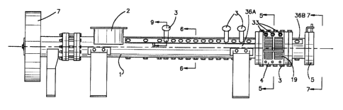
Flg. l shows an extruder ln accordance wlth the present
lnvention and which lncludes a barrel l, an entry aperture or feed
hopper 2 to accept lncomlng oleaglnous materlal for processlng,
and one or more steam meterlng valves 3 for the ln~ectlon of steam
dlrectly lnto the oleaglnous materlal wlthin the ~arrel l. Barrel
l lncludes a dralnage sectlon ~ to allow llberated oll to flow out
through the barrel wall, and a dlscharge dle platP 5 through whlch
21 1 3 ~ 3~ ~ 27768-43
the treated material flows. A standard cutter mechanlsm (not
shown) may be mounted ~ust outslde the dle plate, to cut the
extru~ed solid materlal lnto pellets (or "collets").
Wlthln the barrel 1 ls an axially rotatlng shaft 6 (Flg.
2) wlth dlscontlnuous worm fllghtlng 6A. The shaft 6 ls rotatable
by means of a motor and a V-belt (not shown) attached to drlve
sheave 7 and thrust sleeve 8. Conventlonal bearlngs 9 are provl-
ded wlthln a thrust case lO at the feed end of the æhaft.
The shaft 6 carrles a feed worm ll havlng a relatlvely
long pitch and wlth double wrap to lncrease lts efflciency. Shaft
6 also carries two transltlon worms 12 and 13 wlth pltches selec-
ted to accept the solld materlal from the feed worm 11 and to
allow any entrapped alr to escape back through the entry aperture
2. Thereafter, the shaft carrles a successlon of compresslon
worms 14, 15, 16, etc. which sub~ect the materlal being processed
to a continual bulld-up of pressure as the materlal ls transported
down the length of the barrel.
The extruder accordlng to the present lnventlon prefer-
ably lncludes, between the lndlvldual worm fllghts ~A, one or more
rows of lnwardly extendlng breaker plns 17 (Flg. 2). Breaker plns
17 extend inwardly lnto barrel l and prevent rotary motlon of the
oleaglnous materlal wlthln the channel area 18 between shaft 6 and
barrel 1. Thls furnlshes a hlgh degree of relatlve motlon between
- , '
i3 ~ 7~
22 27768-43
the materlal wlthln the breaker pln area and that wlthln the
fllght area of each compression worm.
Dralnaae Section Deslan
The baslc structure of the dralnage sectlon 4 lncludes a
frame element 100 (Flg. 3) whlch has at one end a flrst flange 102
for attachment to an upstandlng flange 104 (Flg. 2) on solld wall
barrel sectlon 36A; a second flange 106 at the opposlte end of
element 100 for attachment to a flange 108 on solld wall barrel
section 36B; and a palr of longltudlnally extendlng support posts
llO extendlng between flange 102 and flange 106. First flange 102
~Flg. 4) ls provlded wlth a plurallty of bolt holes 112 for re-
celvlng bolts (not shown) whlch secure flrst flange 102 to barrel
sectlon 36A. Slmllarly, second flange 106 lncludes a plurallty of
bolt holes (not shown) for securlng second flange 106 to solld
wall sectlon 36B.
The drainage sectlon 4 (Flg. 5) of the barrel wall ls
bullt up from an assembly of barrel bars 19 lylng side-by-slde,
fltted together ln keystone-llke fashlon. The barrel bars l9 are
held ln place by tapered glb bars 20, 21 whlch are pulled down
between the barrel bars by means of threaded studs 22, 23 and
locklng nuts, 24, 25. The glb bars 20, 21 are attached to a
serles of frame members 26, 27 and, when pulied down, put lateral
r~ ~
23 27768-43
pressure on the barrel bars wedglng them flrmly ln place ln the
frame members 26, 27 .
The actual dralnage cages of drainage sectlon 4, which
are half-cylindrlcal cage assemblles, left and rlght as seen ln
Fig. 5, are assembled onto frame member 100. As seen ln Flg. 5, a
series of upper tle bolts 33 and lower tle bolts 34 cooperate wlth
four longltudinally extendlng clamplng bars 29, 30, 31 and 32 to
clamp frame members 26 and 27 onto opposlte sldes of the
longitudlnally extendlng support po~ts 110 of frame member 100.
Tle bolts 33~ 34 e~tend through bolt holes 120 in support ports
110 .
The structure of dralnage sectlon 4, as thus descrlbed,
makes several malntenance operatlons readily performable. For
example, should the drainage spaces between barrel bars 19 become
clogged, the drainage cages may simply be removed from the frame
element lO0 for cleaning, wlthout disassembling the extruder as a
whole. Also, should the wormshaft 6 re~ulre malntenance, breaker
bolts 17 in dralnage section 4 and/or ln solld wall barrel sectlon
36A, 36B may be removed, allowlng the shaft 6 to be pulled out
axlally.
The flanges 102 (Flg. 2) and 106 on dralnage sectlon
lO0; the flange 104 on barrel wall 36A; and the flange 108 on
barrel wall 36B; are all lnterfltting so that the dralnage sectlon
4 may be lnterchanged, for e~ample, wlth the barrel wall sectlon
~c
24 ~ 27768-43
36B; the dle plate 5 may be bolted dlrectly to dralnage section 4;
or further dralnage sectlons 4 or solld barrel wall sectlons 36B
may be added as deslred. Such interchangeabllity allows for great
flexlbility ln assembling an extruder accordlng to the present
lnventlon to fit a partlcular appllcatlon.
The barrel bars 19 are dlsposed ln such close lateral
contact wlth each other as to prevent solld materlal from escaplng
radlally therebetween, but to permlt llquid to be squeezed through
the mlnute lnterstlces formed by placing spacers 35 (see Flg. 10)
between ad~acent barrel bars 19.
The dralnage section 4 may advantageously be mounted at
dlfferent posltlons along the barrel 1. It may be mounted, as
shown ln Flg. 1, after the solld walled sectlon 36A and before the
final solld wall sectlon 36B. Alternatively, the dralnage sectlon
4 may be lnterchanged wlth the flnal solid wall sectlon 360 of the
barrel to provlde dralnage lmmediately ahead of the dle plate 5.
There may also be provided a longer solld-walled dlscharge sectlon
36B between the dralnage sectlon 4 and the dle plate 5. For
materlals whlch when processed produce relatlvely high levels of
liberated oil, two dralnage sectlons 4 placed end-to-end, or one
section of longer length, can be used.
At the dlscharge end of the barrel 1 is a die plate 5
(Figs. 1, 7) whlch ls bored to provlde a plurallty of reduced exit
apertures 5A, havlng shoulders which serve to retaln dle lnserts
27768-43
37 (shown ln Flg. 8). By thls means, dles of dlfferent aperture
dlameters and land lengths and number of apertures per lnsert may
he substltuted.
Slnce lt is preferable to lncrease the molsture content
(when re~ulred~ of the oleaginous materlal belng processed, by the
lnjectlon of steam, and slnce lt ls preferable to furnlsh a hlgh
percentage of the BTUs requlred for heatlng of the oleaglnous
materlal by live steam ln~ectlon, the present lnventlon may employ
one or more steam lnjectlon valves 3 (Flgs. 1 and 9) for such
lG in~ectlon. Steam ln~ectlon valve 3 lncludes a houslng 38 havlng a
threaded portion 39 adapted to lnterfit one of the threaded aper-
tures such as are occupled by breaker plns 17 as shown ln Fig. 2.
The houslng 38 also has a nonthreaded portlon 40 whlch extends
inwardly lnto the channel 1~.
The houslng 38 ls hollow and ls provlded at the outward-
ly dlrected end thereof wlth a thread fltted cap 41. A valve stem
42 ls mounted concentrlcally wlthln the houslng 39. The valve
stem 42 has an lntermedlate threaded portlon 43 thread fltted
wlthln a bore 44 of sald houslng. The valve stem pro~ects out-
wardly from the lntermedlate portlon 43 through an aperture in thecap 41, and ls provided at lts outermost end wlth a handle 45.
Packing 46 ls compressed under the cap 41 whereby the stem 42 ls
sealed ln relatlon to the bore 44.
~he ~alve stem 42 ls dlametrlcally reduced, at lts
. .,
26 ~ 5 ~, ~ 27768-43
inwardly dlrected portlon and ls provlded at the end thereof with
a frustoconlcal valve closure member 47 whlch has a complementary
lnter flt with the frustoconlcal valve seat 48. A small, cyllndrl-
cal plunger 49 extends coaxlally lnwardly from the valve closure
member 47 and closely lnterflts a small, cyllndrlcal bore 50 ln
the innermost end of the houslng. The lnterfit between the small
plunger 49 and the bore 50 ls preferably such that when the valve
closure 47 is unseated by turnlng the handle 45, pressurlzed steam
may be admltted at W and forced past the plston 49 to enter lnto
the channel 18, but the materlal belng processed cannot easlly
enter the lnterlor of the ln~ectlon valve from the barrel. The
positlon of the dlscharge end of the ln~ectlon valve relatlve to
the hub surface of the shaft 6 ls controlled by a threaded nut 51
used to lock the valve ln posltlon on the barrel.
For ln~ecting water or steam, at W, into an oleaglnous
materlal being processed ln the extruder according to the present
lnvention, valve 3 may be employed ln place of one of the breaker
bolts 17 toward the lnlet end of the apparatus, or as an alterna-
tlve, water could be added directly into the feed hopper 2. When
valve 3 ls being employed for steam in~ection, lt advantageously
replaces a breaker bolt 17, preferably ln the area approxlmately
one-half to three-quarters of the way along the length of the
apparatus toward the dlscharge end, as shown ln Fly. 1.
7 ' ''
27 i 3 ~ 7 9 ~77~8--43
eed Worm Deslqn
As noted above, the processlng of flaked ollseeds in
present extruders is not nearly as efficient as lt could be,
because of the relative inefflciency of the fee~ worm structure as
compared to that of the compactlon worms. That ls, present feed
worm deslgns cannot feed enough sollds to make full use of the
compactlon worm's capacity. Accordlngly, it has long been deslred
to flnd a feaslble way to lncrease feed worm capacity.
There have been proposed varlous ways to do this. One
way is to provide a force feeder whlch would increase the effl-
ciency of the feed worm. (Gravlty fed feed worms are only about
33~ efflclent--that ls they actually convey about 3~ of what they
could theoretically convey. Thls is because of the open hopper
above the feed worm and the tendency of the feed materlal to pile
up and fall behind the flight as the shaft rotates.) However, a
force feeder adds signlflcantly to the cost of the extruder.
Another way to lncrease feed worm capacity ls to make
the barrel diameter larger at the feed end, and funnel it down to
the narrower worklng dlameter farther down the barrel. Thls would
allow for more volume to be conveyed because the feed worm fllghts
would be deeper, but thls would agaln add slgnlflcantly to the
cost of the extruder.
Accordlngly, the present lnventlon provldes for lncreas-
ing feed worm intake, not by the use of a force feeder, and not by
.,
:
7 9
28 27768-43
enlarglng the barrel dlameter, but rather by lengthenlng the pltch
of the feed worm. Thls presents the problem, however, that a long
pitch fllght of shallow channel depth (the dlstance between the
hub of the shaft and the lnslde of the barrel) makes the worm even
less efflclent than a shorter pltch fllght, and makes lt more dlf-
flcult for the entrapped alr comlng ln wlth the flakes to flow
back, counter-current to the flow of flakes, so that the alr can
escape out of the feed hopper. If the air cannot escape back
through the feed hopper, lt wlll become trapped ln the extruder
and prevent an adequate throughput of flakes. Accordingly, the
present lnventlon uses double fllghtlng on the feed worm to allow
for increased capaclty, due to the long pltch, wlth no slgnlflcant
loss of efflclency due to the double wrap; and, further, uses one,
or preferably a palr of decreaslng pltch transltion worms between
the hlgh volume feed worm and the exlsting compactlon worms ln the
orlglnal extruder shaft conflguration.
An earlier deslgn feed worm had a slngle flight feed
worm wlth wraps spaced four lnches apart and at a pltch of four
lnches. The compactlon worms had a pltch of 2-1/2 lnches. The
volumetrlc dlsplacement of the compactlon worm was 41.7% less than
the dlsplacement of the feed worm. It was known from the opera-
tion of the orlglnal extruders that the alr could flow counter
current to the solld materlal wlth that much reductlon ln volum-
etrlc displacement between the feed worm and the press worm.
2~ ~7-76~-~3
The present lnventlon provldes a new feed worm 11 wlth
about 2~ times the capacity of the orlglnal feed worm and yet
which stlll allows for the escape of alr therethrough. Keeping
the hub diameter and the barrel lnside diameter the same requires
a pitch of 10-1~2 lnches. Uslng a double wrap allows the fllghts
llA, llB to be 5-1/4 lnches apart, whlch is close enough to the
orlglnal 4 lnches not to cause a slgnlflcant decrease in efflc-
iency~
Thls new deslgn provides a 78% reduction in volumetric
dlsplacement golng from the feed worm to the compactlon worm,
whlch, however, standing alone, ls too much to allow for the free
flow of trapped alr to escape back through the feed worm 11 to the
feed hopper 2. Therefore, one, or preferably two transltlonal
worms 12, 13 are dlsposed between the feed worm 11 and the compac-
tlon worms 14, 15, 16, etc. The transltlon worms 12, 13 are de-
slgned, wlth careful attentlon to volumetrlc dlsplacement, to
allow for a stepwlse reductlon ln volumetrlc dlsplacement from
worm-to-worm that was not substantially dlfferent than the 41.7%
known to be adequate to allow backflow of entrapped alr; and yet,
allows each worm to have 320 of wrap and lnterflt wlth as many of
the exlstlng breaker bolts 17 in the exlstlng barrel 1, as pos-
slble.
Flg. 2 lllustrates the new and lmproved extruder feed
worm deslgn ln accordance wlth the present lnventlon. Disposed
30 1 3 ~ 9 27768-43
underneath the gravlty feed hopper 2 is the feed worm 11. Feed
worm 11 is a long-pltch, double-wrap worm havlng fllghts llA and
llB. The feed worm 11 ls followed by two decreaslng pltch transl-
tlon worms 12 and 13. The new worm deslgn provldes for a volu-
metrlc dlsplacement reductlon of 42.2% from feed worm 11 to tran-
sltlon worm 12; of 44.1% from transltlon worm 12 to transltlon
worm 13; and 32.1% from transltlon worm 13 to compactlon worm 14.
Thls allows for a total volumetrlc dlsplacement reductlon from the
feed worm to the compactlon worm of 78%, but lt ls done stepwlse
ln three lncrements that are not substantlally different from the
41.7% known to be adequate.
Operatlon
In operatlon, the oleaginous materlal to be processed ls
fed lnto barrel 1 vla feed hopper 2. Feed worm 11 and transltlon
worms 12, 13 lnltlally convey the solld materlal along barrel 1.
The deslgn of the feed worm 11 and transltion worms 12 and 13 ls
such that a large volume of low bulk denslty flakes can be accept-
ed lnto the compresslon barrel 1 by the lnltlal long pltch, double
flighted worm 11 whlch wlll pass the flakes on to one or more
transltlon worms 12 and 13. Transltlon worms 12 and 13 wlll, by
means of progresslvely reduced pitch, and dlscontlnuous wrap,
begln the compactlon and de-alrlng of the flakes, allowlng the alr
whlch fllled the volds between the flakes, to flow counter-
~" .
7.~
31 27768-43
current, back through the feed hopper 2, and propelllng the de-
alred material lnto the area of the compactlon worms 14, 15, 16,
etc. which compress the materlal to an lncreaslng degree along the
length of the barrel.
If the raw materlal belng fed into barrel 1 is too dry,
for example, lf lt ls at a moisture content of less than approxl-
mately 6%, water ls elther in~ected by means of valve 3 lnserted
lnto, for example, the fourth breaker bolt openlng from the feed
end of the machlne, or ls plped directly lnto the feed hopper 2.
Sufflcient water is thus added to ralse the molsture content of
the materials to preferably the range of 6%-8%. As th~ materlal
ls conveyed along barrel 1 through the relatively narrow channel
18 between the shaft 6 and barrel 1 (Flg. 2), a frlctional heat ls
evolved as a result of the relatlve motlon between the shaft 6 and
the solld materlal belng process~d. As a consequence, the temper-
ature of the solld material i3 increased durlng lts course of
travel through the apparatus. Live steam may then be ln~ected
into the solid mass through one or more valves 3, located in
breaker pln openings past the center half of the barrel 1. Enough
steam ls ln~ected lnto the solid material so that the moisture
content of the material ~ust ahead of the dle plate 5 ls prefer-
ably ln the range of 10~ to 13~, but permissible ln a range of 7%
to 20%. Collets can be made at still higher moisture content, but
it ls preferred not to operate at such hlgh molsture levels
.t
'
32 ~ 3 ~ ~ ~ 7 9 27768-43
because of the requlrement to dry the collets before they enter
the solvent extractor.
By additlon of the llve steam, the temperature of the
solid materlal (as measured by a thermometer readlng the tempera-
ture of the solld materlal near the barrel wall, not at the hotter
locatlon ad~acent the worm shaft) ls also lncreased. That, ln
con~unction wlth the heat generated by frlctlon, can ralse the
temperature of the materlal to the preferred range of 2Q0F to
250F, but permlsslble in a range of 190F to 300F. Dry steam,
if used, especlally at temperatures ln excess of 212F., achieves
a most efflclent lncrease ln the temperature of the ollseed
materlal.
The deslgn of the compresslon worms 14, 15, 16, etc. and
the deslgn and selectlon of dle ~nserts 30 (Flg. 7) are such that
the mechanical pressure lmposed upon the solld materlal ls hlgher
than the steam pressure generated wlthln the materlal. As a con-
sequence, any moi~ture content wlthln the solld materlal ls maln-
talned ln the llquld state. By maintalning thls molsture ln the
llquld state, a hlgher rate of heat transfer ls realized between
the shaft and the solld materlal.
There ls a gradual bulldup of pressure along the length
of the barrel 1. At the feed hopper the pressure ls atmospherlc.
In a machlne whlch might be constructed ln accordance wlth the
present lnventlon, the barrel 1 would be eight feet ln overall
. ,
~ ,
7 ~
33 27768-43
length~ About tllree feet lnto the barrel, where water may be
ln~ected, the pressure would be 40 to 100 psl. A~ut flve feet
lnto the ~arrel, where steam may be ln~ected, the pressure would
be about 100 to 150 psi. There ls a rather sharp rlse ln pressure
along the last three feet of the barrel usually resultlng in flnal
pressures of 200 to 600 psl at the dle plate, but the full range
ls 100 to 1000 psl at the dle plate.
The pressure wlthln barrel 1 ls a dynamic pressure ex-
erted upon the material by the rotatlng shaft 6, but allowlng for
a backflow of some of the material along the pie shaped openings
on the wrap of the worms 6A. (There ls only 320 of wrap, leavlng
40 with no wrap.) The amount of backflow is dependent upon the
softness or stiffness of the materlal being extruded. The soft-
ness or stiffness is influenced by the moisture level of extru-
slon, and by the oll ~or other lubrlcant) level of the material.
The backflow would lmmedlately allow the pressure to adjust ltself
so that there ls always a pressure gradlent golng from a low value
progressively towards a hlgher value at the dle plate.
Even ln the area of the dralna~e section 4, the pressure
in the extruder barrel 1 is to an extent self-regulatlng. The
pressure lnslde the barrel 1 upon the materlal belng processed ls
constantly lncreaslng as the materlal advances from the lnlet
openlng 2 toward the die plate 5 at the end of the barrel 1. The
openlngs in the wall of drainage sectlon 4 are sized so as to
1 3 ~
34 277~8-43
allow for the passage of llquld ~llberated oll) wlth only a mlnl-
mum escape of sollds. As the pressure ln the barrel 1 lncreases,
more oll flows out of the openlngs in the dralnage sectlon 4,
thereby reducing the volume of compressed materlal wlthln the
barrel 1, whlch loss would tend to reduce the pressure at that
polnt. ~ut, because of backflow, the overall barrel pressure is
smoothed out so that there is stlll a progresslve lncrease ln
pressure as the materlal advances through the barrel, but the
magnltude of the pressure is not as great as lt would have been
had none of the oll passed through the drainage sectlon 4.
Because of the pressure lmposed upon the materlal, some
of the oll lmbedded in the ollseed materlal ls llberated durlng
the worklng of the material. Some of thls llberated oll may be
re-absorbed lnto the solld materlal. However, if the overall oll
content of the materlal ls hlgher than approxlmately 30%, some oil
would remaln llberated in pockets of free oll that would lnterfere
wlth the steady-state discharge of collets through the dies. For
those oilseeds that present this problem, such as cottonseed,
whlch contains approxlmately 30% oil and occaslonally presents
this problem, or other ollseeds containing more than 30% of oil,
whlch oilseeds would usually present this problem, the present
invention with the drainage section 4 allows dralnage of the oll
from the barrel 1. Thls drainage sectlon 4 can be located anywhere
between the midpoint of the barrel 1 and the die plate 5, but is
':
' ~- : :
,
~ 3~
35 27768-43
preferably disposed at a point about three-fourths of the dlstance
downstream from the inlet 2 of the extruder (one-fourth of the
dlstance upstream of the dle plate 5). The dralnage sectlon 4, as
noted above, could extend up to the area of the dle plate 5, or it
could termlnate some dlstance from the dle plate 5. The dralnage
sectlon 4 may be located ln a portion of the extruder whereln the
vapor pressure of the water content of the materlal belng process-
ed slgnlflcantly exceeds atmospherlc pressure, and lt wlll stlll
function properly.
One preferred embodiment of the apparatus of the present
lnventlon provides for the last quarter of the overall length of
barrel 1 to be a removable section, one-half of which is perforate
to allow for dralnage, the other half solld-walled. Such a sec-
tlon of barrel wall may be provlded in two verslons: one wlth the
dralnage section 4 ad~acent to the dle plate 5, the other wlth the
solld wall adjacent to the dle plate 5. Or, as an alternate, thls
sectlon can, by ~udiclous spacing of the posltions therealong of
~ breaker bolts 17, be made to be reversible so that lt can, itself,
: be placed ln elther orlentatlon.
It ls not an ob~ect of the present lnvention per se to
cause a llberatlon of oil but, rather, to form a porous extract-
able collet; and, lf ln doing that, some of the oil ls llberated,
to provlde a means for the llberated oll to escape from the inter-
ior of the extruder in a fashion that allows the extruder to
X-
, ~ . ` .
.
36 ~7768-43
contlnue dlscharging collets ln a steady-state condltlon. The
libera~e~ oll is preferably dlrected to a polnt outslde the extru-
der where lt can be collected and passed downstream to the oll
processlng equipment ln the solvent plant. One way to do thls ls
to provide a shroud around the dralnage area of the barrel, wlth a
bullt ln sump at the bottom (shroud and sump not shown ln the
flgures) the oll from the sump belng pumped to ~oln the desolven-
tl~ed extracted oll prlor to ~iltratlon. If there is a small
quantlty of oll, or lf the oll contalns more sollds than the fll-
ter can handle, lt can be pumped lnto the extractor after the col-
lets have formed a bed to let the sollds be flltered out by the
collets as the oil passes down through the bed. Or the oll can be
passed over a screen to free draln the sollds, the sollds then
belng mlxed in with the materlal enterlng the extruder for re-
agglomeratlon. The screened oll, whlch iQ pressed rather than
solvent extracted, contalns fewer lmpurltles, ~ecause presslng
removes prlmarlly trlglycerides, whlch ls the vegetakle oll
desired, whereas the solvents used ln extractlon remove other
llpld compounds, such as phosphatldes and waxes whlch are dif-
flcult to remove from the flnlshed product. For thls reason,press oll can find a preferred market ln some appllcations over
extracted oll. The use of the present invention would allow for a
stream of thls higher quallty oll to be diverted into a speclal,
higher priced market.
t~`
~ '
~7 ~l768-43
The ~erm "oil" ls used hereln to refer generally to
fluid whlch is llberated from the solid materlal belng treated ln
the extruder and allowed to drain out. It shoul~ be noted that
the oil may be a fat or other lipld, or a liquld wax, or other
fluld oll-llke componen~ which ls so liberated, dependlng on what
material ls belng processed. Thus, use of the term "oll" herein
when referrlng to the present inventlon ls lntended to encompass
any such llberated material.
Even if the drainage section is disposed along the bar-
rel 1 at a high pressure region thereof, most of the moisture orwater will stay in the solid material while the oil drains out.
Some of the solid material wlth lts absorbed moisture will escape
along wlth the liberated oil, but this can be kept at an accept-
ably low level by a ~udlclous cholce of barrel bar spacing.
The length of tlme for a materlal of the type herein-
above ldentified to be processed through an apparatus as shown
herein may be in the range of 10 to 30 seconds. Although the
speclfic length o~ tlme ln process ls not crltlcal, a relatlvely
short resldence time, as ls posslble with the present invention,
wlll help ln reduclng any deleterlous side effects resulting from
relatlvely high temperatures for sustalned periods of time on the
oleaginous material belng processed.
The solld materlal ~ust ahead of die plate 5 might be at
a molsture content of 13% and at a temperature of 110C. under a
,
7 ~
38 27768-43
mechanlcal pressure ln the range of 100 to 1,000 p~l, but pre-
ferably ln a range of 100 to 300 psl. Upon dlscharglng from the
apparatus through the Apertures in dle plate 5 lnto normal atmos-
pherlc pressure, there is an lnstantaneous pressure drop 80 that
some of the water ln ll~uld form vaporlzes, thus causlng an expan-
slon of the lssulng solld materlal, whlch results ln a porous
structure of such materlal. Further, by convertlng water ln the
llquld state to a vapor state there ls a decrease ln molsture o~ ~-
the solld materlal wlth a slmultaneous coollng of the materlal.
~ecause of the porous nature of the sollds, they may contlnue to
evaporate molsture, and may more readlly be permeable for the
leachlng actlon of solvent ln a solvent extractor to extract the
oll from the oleaglnous materlal.
From the above descrlption of a preferred embodlment of
the lnventlon, those skllled ln the art wlll percelve lmprove-
ments, changes and modlflcatlons. Such lmprovements, changes and
modlflcatlons wlthln the sklll of the art are lntended to be
covered by the appended clalms.