Note: Descriptions are shown in the official language in which they were submitted.
1 3234 1 1
This invention relates to an actuation or control
device for electrical appliances. The device can
control an operating paramet~r such as speed or heat
outlet.
To operate electrical appliances, it is frequently
necessary to provide an actuation device permitting a
variation of at least one operating quantity of the elec-
trical appliance by means of a primary detector and a
subsequent circuit arrangement. From DE-OS 2,848,749 an
actuation device according to the preamble of the main
claim is already known. This actuation device comprises
a multi-stage switch and a coil which is part of the
transformer of a charging circuitry. For controlling the
rotational speed, this coil can be optionally placed in a
circuit of a motor o~ an electric tooth-brush via a tap
by means of the multi-stage switch. While this actuation
device merely permits predetermined individual rotational
speed values to be set, it does not allow a continuous
adjustment of the rotational speed. Further, it is
rather problematic in practice to realize switches for
such uses in tooth-brushes, oral jet devices, electrical
household appliances, shavers and the li~et because for
one thing such switches should be water-proof or water-
protected to protect the user of such appliances and to
ensure their safe operation, and for another thing
moist~re or water should be prevented from entering the
interior of the housing of the electrical appliance.
It is therefore an object of the present invention to
improve upon an actuation device according to the pre-
amble for electrical appliances such that a continuous
open- or closed-loop control of at least one operating
quantity of the appliance is possible by means of a
single movable control device provided on the housing of
the electrical appliance. At the same time, high user
safety is to be ensured, and the operability o~ the ac-
tuator is not to be impaired by environmental effects
such as humidity and contamination.
.
'
2 1 32341 1
This requirement is satisfie~ by an actuation
device, a primary detector for the genera~ion of
controlled variables, the primary dekector including
a movable magnetic field varying element which is
arranged on the outside of the appliance housing and
produces magnetic fields of varyin~ field strengths in
dependence on its position, and an element fixedly
disposed on the electrical appliance and sensi~ive to
ma~netic Eields, the field-sensitive element being
dispo~ed inside the housing including a magneto-
resistive element and being adapted to produce an
output quantity which is a measure of the field
strength at the site of the field-sensitive element,
a circuit arrangement inside the housing, and means
~or delivering the output quantity to the circuit
arrangement, the circuit arrangement incorporating at
least one control function responsive to the output
quantity which in turn operates on the operating
quantity of the electrical appliance.
The means indicated therein enable an operating quan-
tity of the electrical appliance to be adjusted to nearly
every possible value using a single movable primary de-
tector. At the same time, high operational and function-
al reliability is ensured because the need to provide
physical connections between the field-influencing or
field-producing element and the field-sensitive element
is obviated. The field-producing or field-influencing
element is capable of being actuated, for example, by a
user of the appliance, operating on the field-sensitive
element which, for example, is fixedly disposed in the
housing of the appliance, without mechanical connections
or electrical leads between the two elements being neces-
sary. Nevertheless, the operating quantity of the elec-
trical appliance is largely continuously adjustable or
controllable to a high degree of precision by an evalua-
tion of the output quantity of the field-sensitive
element.
Because the circuit arrangement incorporates a
threshold function and/or a proportional ~unctlon, the
operating quantity of the electrical appllance can be
turned on or off while at the same time being set to pre-
determined values using a single movable element, wlthout
the need to provide the movable element with a notch~ng
mechanism.
,
:
- ' ' .
. .
., -, . , ' ,, ~ : '.,, . . . ' '. ', ' :
. .
3 1 3234 1 1 05231
Configuring the movable element as a permanent magnet
or yoke of a permanent magnet and the field-sensitive
element as a magnetore~lstive element affords the ad-
vantage of economy of larg~-scale production and compact
construction, because elements configured in thls manner
are small and relatively inexpensive to manufacture. By
arranging the magnetore~istive element and the circuit
arrangement in the interior of a housing the electrical
appliance and by provlding the movable element on the
outside of the housing of the electrical appllance, the
function of the housing as a means of protection against
humidity, ~ontamnatlon and electric voltage~ becomes
fully effective. In addition~ dispen~ing with the need
for perforations otherwise necessary for conventional
switches or potentiometer~, the housing can be manufac-
tured substantially more easily and economically.
Further advantageous embodiments of the circuit arrange-
ment for processing the signals of the primary detector
will become apparent from the subclaim3 ~n conjunction
wlth the description of the embod1ments.
It ls particularly advantageous to configure the cir-
cuit arrangement as a closed-loop control system for con-
trolling the operating quantity of the electrical
appliance. Although the signal for determining the turn-
on level of the operating quantity of the appliance and
the signal referred to for a largely continuous adjust-
ment of the operating quantity are derived from a single
output signal, that is, the output signal of the primary
detector, the operating quantity is controllable due to
the special configuration o the control system indicated
in the claims. By configurlng~the coupling function
:; ...
.
. . . .
.
.
,' ,
,
, . '1
1 3234 1 1
05231
preferably as a resistor, a very low-cost, but never
theless effective means of accomplishing the coupling
function is provided.
By arranging the field-sensitive element on a pole
shoe of a permanent magnet, in which arrangement the flux
permeating the field-sensitive element is~variable by the
movable element, and by conflguring the movable element,
the pole shoe and the permanent magnet preferably as
shell segments situated concentrically about a houslng
axis, optimum conditions result with regard to the
utilization of space and the adaptation of the actuation
device to the contour~ of substantially cylindrical
housings of electrical appliance~. It proves to be par-
ticularly advantageous if the pole shoe is formed as a
circular ring section with an adjacent angular section
whose foot-shaped free end carries in particular a
magnetoresistive element, because the magnetic circuit
has only minor magnetlcally effective resistances such as
air gaps and the like, so that the field-sensitive ele-
ment ls always exposed to sufficient field strengths and
a satLsfactory resolution is ensured. Further advanta-
geous embodiments of the mechanical constructlon of the
primary detector, also for the open- or closed-loop con-
trol of more than one operating quantity, will become
apparent from the subsequent descrlption of embodiments
and from the; subclaims.
~ ::
In the drawin~s,
FIG. 1A is a view of a primary detector with a
magnetoresistive element;
' ~: ,
. . .
~:
.
.:
.. . . .. . .
` , ' . ' ,
':
1 323~ 1
~ 05231
FIG. 1B is a characteristic wave form of the magneto-
resistlve element of FIG. 1A;
FIG. 2 is an embodiment of an actuation device;
FIG. 3 is an electrlcal schematic illustrating a
first embodiment of a clrcuit arrangement;
FIG. 4 is an electrical schematic illustrating a
second embodiment of a circuit arrangement;
FIG. 5A is a detailed circuit diagram relating to the
electrical schematic of FIG~ 4;
FIG. SB is a graphlcal representation of pulses to
explain the mode of functlon of the circuitry of F~G. 5A;
.
FIG. ~ i9 a cross sectional view of a primary de-
tector illustratinq a first embodiment
FIG. 7 iS a schematic perspective view of a primary
detector illu~trating a second embodiment;
FIG. 8 is a perspectlve view of a primary detector
of round basic shape illustrating a third embodiment;
FIG. 9 is a perspective view of a primary detector
of round basic shape illustrating a fourth embodiment;:
and
FIG. 10 is a perspective:view of a prlmary detector
cf plane basi~ shapo lllustratlng a ifth embcdi-ent.
...
' '
.
'. '
,
, . ~ ' ' ' ' ,
" 1 323~ 1 1
05231
FIG.lA shows a magnetoresistive element 1 known per se
with a pole shoe 2 of soft iron material, a permanent
magnet 3 and a movable element 4O The magnetoresistive
element on the pole shoe 2 is exposed to the magnet1c
leakage flux 5 stemming from the permanent magnet 3O By
means of the element 4 which is slidable relative to the
magnetoresistive element 1, the magnetic leakage flux 5
permeating the magnetoresisti~e element 1 can be
changed. As shown in EIG. 1B, a change in the magnetic
induction B permeating the magnetoresistive element 1
effects a change in the resistance R of the magnetore-
sistive elemant 1. Thus, a position change of the ele-
ment 4 is reflected in a change in the resistance of the
magnetoresistive element.
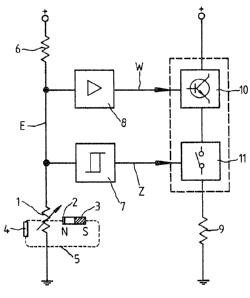
FIG. 2 shows an embodiment of an actuation device of
an electrical appliance. The primary detector is
arranged on a handle or a housing, for example, and
includes the components already described with reference
to FIG. 1A. In FIG. 2, the magnetoresistive element 1 i5
illustrated as a variable electric resistor because only
this is relevant for the explanatlon of the circuit
arrangement.
Arranged in series with the magnetoresistor 1 is a re-
sistor 6, this series circuit being connected between the
two terminals of a DC voltage supply. An electric signal
E which is a measure of the resistance of the magnetore-
sistor 1 and conseguently of the posltion of the movable
element 4 ls applied to a center tap of this serles cir-
cuit. Signal E is connected to the inputs of a circuit
arrangement comprising a proportional function 8 and a
threshold function 7. For the executlon of such func-
','' ' . ' ~ `, ` ' ' .
.
7 1 3234 1 1
~ 05231
tions, reference may be had, for example, to the standardreference work "Halbleiter-Schaltungstechnik" by U.
Tietze and Ch. Schenkt Springer Verlag Berlin, Heidel-
berg, New ~ork, 5O Au1age, in particular page 411 ff.
and page 688 ff.
An output signal W of the proportional function 8 is
suppli~d to a control function 10 which is connected be-
tween the terminals of the voltage supply in series with
a switch function 11 and a load 9. The switch function
11 is controlled by the output signals Z of the threshold
function 7O Depending Ol1 the type of electrical
appliance, the load 9 may be, for example, an electric
,,, . .. ........ ., .. ,, .. --. ~
motor, an electrlc heater or the like, with the operating
quantity to be controlled being then understood to mean
the rotational speed of the electric moto~ or the heat
output of the electric heater~ By means of the control
function 10, the output of the load 9 is continuously
controllable in dependence on the signal W, while the
switch function 11 enables the load 9 to be turned ON or
OFF in dependence on the slgnal Z.
This actuation device thus serves for the adjustment
~nd the ON-OFF ~ontrol o~ an ~perating quantlty o~ a~
electrical appliance includin~ a primary detector which,
for example, is operable by hand. Advantageously, a
single movable element 4 is used for controlling the
turn-on level of the appliance or the operating quantity:
and the variation of the operating quanti~y. : It proves
to be an advantage that the appliance can be turned off
only by setting the operating quantity back to low
values. Conversely, the appliance cannot be turned on
with the operating quantity at maxlmum vaiue~ as, for
, :
-` , - -' . .
-
1 3234 1 1
05231
example, at maximum speed. If the load 9 is, for
example, a blower motor or a heating unit of a hair
dryer, the circuitry illustrated in FIG. 2 permits the
blower or heat output to be readily switched on and
varied under finger control, for example.
If the element 4 is positioned in such a manner that
the magnetic induction increases, the output voltage
(signal E) of the primary detector will also increase.
When the turn-on level of the threshold function 7 is
reached, the switch function 11 is switched to ON. Fur-
ther movement of the element 4 causes the signal E to in-
crease further, so that the control function 10 permits
an increased supply of power to the load 9. Thus, the
operating quantity of the appliance can be set to a
higher or lower value by mean~ of the movable element 4,
the proportional function 8 and the control function 10.
In the process, the switch function 11 remains in the ON
state, having no further effect on the power supplied.
If the element 4 is moved back and the turn-off level
is reached, the threshold function 7 interrupts via the
switch function 11 a further variation of the operating
quantity of the electrical appliance, turning the load 9
off. The turn-on operation and the variation of the
operating quantity of the electrical appliance can be
performed by the user under particularly flne control
using, for example, a single flnger. The proportional
function 8 may be omitted if the output signal E of the
primary datector is su~ficient to control the control
function 10 directly. The turn-on level at which the
operating quantity of the electrical appliance i5 to be
varied continuously can be determined by setting the
. . .
.
.
.
9 1 323~1 1
05231
threshold value of the threshold function 7. This
eliminates the need for complex mechanical adjustments to
determine accurately defined and different turn-on
levels, making the circult arrangement suitabl~ for uni-
versal use. In FIG. 2, as in the subsequent FIGS. 3 to
5, the threshold function 7 may be a Schmltt trigger or
comparator.
FIG. 3 shows a first embodiment of a circuit arrange-
ment in which parts iden~ical to those of FIG. 2 are
assigned identlcal reference numerals. The primary de-
tector of FIG. 3 is illustrated purely s~hematically by
the resistor of the magnetoresistive element 1.
Unlike the c~rcuit arrangement of FIG. 2, the two out-
put slgnals W and Z of the amplifler stage 8 and the
threshold ~tage 7, respectively, are fed to a coupling
function 12 whose output signal Y controls the control
function 10 for the variation and the ON-O~F control of
the operating quantity. The control function 10 com-
prises, for example~ a power transistor which controls
the supply of current to the load 9 in dependence upon
the signal Y at the output o the coupling function 12.
The coupling function may be performed, for example, by
an operational amplifier configured as adder or subtrac-
tor or by a diode gate ~see also "Halblei-
terschaltungstechnik", page 189 ff. and page 147 ff.).
In the embodiment of FIG. 3, a transistor of the con-
trol function 10 is used both as a switch and as a con-
tinuously acting control elementO The circuit arrange-
ment opexates as follows: The output signal Y of the
coupling function 12 brings the tran~i~tor o the control
''.' , ~ ' . ' ''', ' '
.
- lo 1 323~ 1 1
05231
function 10 into conduction whenever the output signal Z
of the threshold function 7 assumes values which, due to
the specific resistance adjustment of the magnetore-
sistive element 1, represent the OFY state for the opera-
ting quantity to be controlled~ This occurs indepen-
dent}y of the output quantity W of the proportional func
tion 8 applied to the second input of the coupling func-
tion 12. If a change in the resistance of the magnetore-
sistive element 1 causes the output signal Z to assume
values signalling the ON state of the operating quantity,
a signal Y proportional to the output signal W of the
propo~tional functlon 8 wlll occur at the output of the
coupling function 12 and more or less cause the transis-
tor of the control function 10 to switch from the OFE
state to the ON state.
FIG. 4 shows a further embodiment of a circuit
arrangement includlng a closed-loop control system in
which parts identical to those of the preceding embodi-
ment~ are assigned identical reference numerals. The
closed-loop control system is formed by the control func-
tion 10, a feedback function 16 9 the coupling function 12
and the proportional function 8. The proportlonal func-
tion B has a first input 14 and a second input 15. Via a
resistor 22, the proportional function 8 has applied to
its first input 14 the signal E present at the center tap
of the voltage divider. If resistor 22 is omitted/ sig-
nal E corresponds to signal W.
For an explanation of the mode of operation of the
closed-loop control system~ lt is assumed first that the
coupling functlon ha~ no eff~ct on the control system and
that the signal V at the output of the feedback functlon
,
11 1 3234 1 1 05231
16 is identical with the slgnal T at the input of the
proportional function ~. The controlled variable X which
is a measure of the value of the operatlng quantity to be
controlled as, for example, the rotational speed of a di-
rect-current motor, is applied to the second input 15 of
the proportional function 8 via the feedback function 16
which may exhlbit a proportional or integral or deriva-
tlve controller action or a comblnation thereof. The
proportional function 8 performs a comparison between
the signal W and the signal T, with the comparison result
occurring at the output of the proportional function 8 as
s~gnal Y ~manipulated variable), operating on the control
function 10 correspondingly. This closed-loop control
system counteracts fluctuations of, for example, the ro-
tational speed of a dixect-current motor or the heat out-
put of a heater, with the poqi~ion of the movable element
4 of the actuatlon device determining the reerence
variable of the operating quantity. In addition to con-
trolling, for example, the blower or heat output of a
hair dryer, the embodiments illustrated may also be used
for controlling the cutt~ng speed of a dry shaver, the
water ~et pressure of an oral jet device or the rota-
tional speed of a motor of a food processor.
Considering the action of the threshold function 7
which has not been included in the considerations so far,
the following modifications result: l~ the threshold
function 7 signals the ON-state of the operating quantity
- this being the case, fox example, if the signal E ex-
ceeds the value F of a reerence signal source 13 -, the
output of the threshold function 7 provides a signal Z
which does not operate on the output ignal T of the
coupling function 12 so that the ~unction of the cloaed-
'
:
`:` ` : ` `
~`'
12 1 3234 1 1 05231
loop control system is not affected by signals o~ thethreshold function 7, By contrast, if the movable ele-
ment 4 lq ln a position correspondlng to th~ OFF state,
the signal level Z occurring at the output of the
threshold functlon 7 causes the transistor of the control
function 10 to be turned off. In control engineering
terms, the output signal Z of the threshold function 7
may also be interpreted as a disturbance signal applied
to the control system, which signal brings the control
function 10 into the OFF state reliably and independently
of the value of the signal W.
FIG. 5A shows a detailed embodiment of a circuit dla-
gram according to the block diagram of FIG. 4. The
threshold function 7 of FIG. 4 includes a first opera-
tional amplifier 31 configured as a comparator and having
applied to its first input 34 the output signal E of the
primary detector via a resistor 1~. As already shown,
the magnetoresistive element 1 is connected in series
with a resistor 17~ The center tap between a fixed
resistor 13 and a resistor 19 connected in series is
connected to a second input 35 of the comparator 31. The
resistors 17, 19 are connected to a positive terminal of
the voltage supply via a resistor 6. A resistor 21
functioning as a feedback resistor connects an output 33
of the comparator 31 to it~:input 35. If the comparator
31 has an open collector output 33, a resistor 211 is
provided between the output 33 and a junction of the re-
sisto~s 6, 19. In parallel a~rangement with the resis-
tors 17, 1 and 19, 13 is a Zener diode 28 which, in co-
operatlon with resistor 6,~ stabilizes the.voltage. The
fixed resistor 13 permits the value of the reference
voltage F to be ad]uated at the second comparator lnput
--
.
-` 13
1 3234 1 1
~ 05231
35. The reference voltage F determines the turn-on/turn-
off level or the point of transition from which the value
of the operating quantlty is continuously adjustable. In
the preceding embodiment, the amplifier staqe 8 is com-
prised of an operational amplifier 32 having applied to
i~s first input 14 the signal W as reference variable and
to its second input 15 the output signal T of the
coupling function 12.
The coupling function 12 preferably consists of a
single resistor 20 inserted between the output 33 and the
input 15. ~dvantageously, the feedback signal Y is
superpose* on the output signal T of resistor 20 at input
15. The second operational amplifier 32 includes a feed-
back resistor 23 lnserted between the output and the
second input 15 and connected to the control function 10
via a resistor 25.
The control function 10 is a p-n-p transistor having
its base connected to a positive terminal o the voltage
supply via a resistor 24 and to the resistor 25. The
emitter of the transistor is directly connected to the
positive terminaI o~ the voltage supply. The collector
of the transistor is connected to the load 9 which in the
present embodiment is a direct-current motor having its
second lead connected to a negative terminal of the :
voltage supply .
The feedback function 16 is provided by~a dlode 29,
resistors 26, 27 and a capaaitor 30. The diode 29
connected in parallel with the load 9 keeps the~ con~
trolled variable ~signal X) ~ree o negative dlrect-
voltage components. Via the RC element comprised of re-
-- :
`: :
:
'` : ' ,
,
- . ,
,
.
,
]~
1 3234 1 1
05231
sistors 26, 27 and capacitor 30, the output signal V of
the feedback function 16 is superposed on the output sig-
nal cf the coupling function 12 (signal T) and applied to
the second input 15. It is also possible to substitute a
three-terminal potentiometer for the two-terminal resis-
tor 20, with the signals Z and Y being then connected- to
the lead~ of the total resistance of the potentiometer
and the output (signal T) being provided by the center
tap. As operational amplifier, type LM 393 may be used,
for example.
The mode of operation of the circuitry illustrated in
FIG. 5A will be described in the following. In FIG. 5s,
the puIse diagram "1" describes the shape of the output
voltage (signal E) of the primary detector or the
reference variable ~signal W). For reasons of simpli-
city, output signal E is assumed to change linearly. It
is further assumed that the circuitry is in the OEF state
and the movable element 4 of the primary detector is in a
position in which the magnetoresistive element 1 has a
residual resistance. Accordingly, the output signal E in
pulse diagram "1" has a low value which is caused by the
residual resistance of the magnetoresistive element 1.
As the element 4 continues to be moved slowly, the resis-
tance of the magnetoresistive sensing element 1 as well
as the output signal E will increase continuously. Eor
the period between to and t1 it is assumed that the
reference voltage ~signal F) is greater than the output~
signal E. Because signal E assumes values smaller than
the reference voltage F until time t1~ the maximum output
voltage Z resYdes at outpùt 33O For the period between
t0and t1~ the maximum voltage value of signal Z is thus
applied to the second in~ut 15, this value being greater
~' ,
- '' ` '' - .
:
l 323~ 1 1 05231
than the voltage W at the first input. Consequently, the
full operating voltage ~signal Y~ of the circuit arrange-
ment occurs at the output of the second comp~rator 32,
and the transistor of the control function 10 is non-con-
ducting preventing current flow through the load 9O
At time tl, positioning the movable element 4 corre-
spondingly causes the signal E to exceed the reference
signal F, the voltage Z at output 33 dropping to zero
value (or, in the event of a bipolar voltaye supply,
approximately to the value of the negative voltage
supply), causing also the resi~tor 20 of the coupling
function 12 to assume this value and to form a parallel
circuit with resistor 27.
The voltage at capacitor 30 drops to low values sub-
stantially with the time constant resulting from resis-
tors 20, 27 and capacitor 30 (pulse diagram "4"), with
the effect of the load 9 on the time constant being ne-
glected in the chart. ThP voltage drop across capacitor
30 ~signal V) produces after a short time the situation
that the voltage at the first input 14 assumes again
values greater than the voltage at the second input 15
and that ths output voltage of the second comparator 32
drops to a low value (pulse diagram "5"; period between
t1 and t2). The translstor of the control function 10
becomes conducting causing current to flow through the
load 9, the occurrence of a signal X in dependence on the
operating quantlty (for e~ample, the rotational speed of
an electric motor used as the load 9), and the charging
of capacitor 30. The voltage at capacitor 30 ~signal V)
rises again until at time t2 the voltage value predeter-
mined by the movable element 4 is reached.
. . .
' ' - , ,
~323~1 1
16 05~31
If the voltage of capacitor 30 (signal V) exceeds the
voltage at the first input 14, the output of comparator
32 switches immediately to positive operating voltage
values. The transistor turns off and the rotational
speed of the motor hecomes reduced momentarily. The
voltage across capacitor 30 drops until the output of
comparator 32 goes again down to low voltage values when
at time t3 the voltage o capacitor 30 is again below the
voltage value of the signal W at the first input 14 of
the second comparator 32.
As shown in the pulse diagrams "4", "5" and "6", con-
trol of the rotational speed of the motor is accomplished
by turning the motor on and off through varying pul~e/no-
pulse ratios, the ratio being predetermined by the posi-
tion of the element 4. Accordingly, in decoupling the
control system from the threshold function 7 in the ON
state, resistor 20 is assigned an important function in
that approximately the potential of the negative terminal
of the voltage supply is then applied to output 33. The
resistor 20 of the coupling stage 12 preferably has a re-
sistance of 10 kohms. If the voltage value of signal E
drops below the value of signal F as a result of a return
movement of the control device 4, the voltage at output
33 rises to a maximum value, and the transistor is cut
off ln the manner previously descrlbed.
The circuit arrange~ent combineæ with the manually
operable primary detector to form an actuatlng and~
control system for at least one operating quantIty of an
electrical appliance~ On the other hand, the primary de- ;
tector represents an 1nterface betw~en a mechanical
.
:
.
17 1 3234 1 1
05231
system and an electrical system, that is, it tr~nslates
th~ action o~ a ~orce exerted, for example, by a flnger
on the mo~able element 4 into an electric quantity to be
evaluated by the circuit arrangement.
In the following, preferred embodiments of the
mechanical construction of the primary detector will be
described which cooperate with the circuit arrangement
described in a very advantageous mann~r.
FIG. 6 is a cross-sectional view of a first embodiment
o~ a pre~erably manuallyoperable primary detector for an
electrical appliance of barrel-shaped b~sic structure.
The primary detector serves for the adjustment of at
least one operating quantity as, for example, the rota-
tional speed of an electric motor o~ an electrical
appliance. The barrel-shaped electrlcal appliance may
be, for example, an electric tooth-brush or an oral jet
device or the like. In the center of the dotted housing
shank body 115, a tubular clearance 105 is provided which
may serve the function of receiving current- and water-
carrying lines, for example. The barrel-shaped housing
shank body 115 extends along a longitudinal axis A shown
as a dot in a center of the clearance 105.
Embedded in recesses of the housing shank body 115 are
the permanent magnet 3 and the pole shoe 2 which is made
of a soft iron material. The permanent magnet 3 and the
pole shoe 2 are constructed as cylindrical shell segments
shown in the Figure as circular-ring sectors layered in
serial arrangement.
' ' . '
. .
1 323~ 1 1
18
05231
Formed on a longltudinal edge of the pole shoe 2 is an
arm-shaped angular section 141 whose foot-shaped free end
146 carries an element which is sensitive to electric or
magnetic fieldst detects the position of the movable ele-
ment 4 and is preferably configured as a magnetoresistive
element. The arm-shaped angular section 141 extends
approximately radially to the longitudinal axis A, being
dlmensioned such that the magnetoresistive element 1 is
arranged at the edge of the housing shank body 115.
The foot-shaped free end 146 terminates in an area of
the housing shank body 115 which lie.~ approximately oppo-
site the permanent magnet 3 and is not occupied by the
magnet. The position of the ad~acent magnetoresistive
element 1 has been chosen such that it is in the opera-
ting range of the element 4 whlch is equally constructed
as cylindrical shell segment, is embedded in a cylindri-
cal control sleeve 114 and rotatable therewith about the
longitudinal axis A.
The element 4 which is a soft iron material or a per-
manent magnet is capable of being turned together with
the cylindrical control sleeve 114 within the range of
the arc or actuating travel "m" between points s and C,
with the individual positions being indicated by a mark
149. The length of the arc and the position of the mag-
netoresistive element are so dimensioned that the:
magnetoresistive element 1 is overlapped by the element 4
irrespective of whether the mark 149 is at end position B
or C. The cylindrical shell segments of the pole shoe 2
of the perman,ent magnet 3 and the element 4 with the
cylindrical control sleeve 114 are conformed to the
hou ing contour or hous~ng curvature o~ the electrical
. . .
.
.
~ , `
19 132~41 1
05231
appliance, with the pole shoe 2 forming the innermost
shell segment, the permanent magnet 3 the middle shell
segment and the element 4 the outermost shell segment.
The stationary parts ~115, 1, 2, 141, 146, 3) may be
referred to as inner parts which are adapted to be herme-
tically sealed to environmental effects by a sealing
layer a~, for example, a housing 106 of the electrical
appliance. The sealing layer or the housing 106 prevents
water and moisture from entering and ensures a safe func-
tion of the inner components including the circult
arrangement, in addition to protecting the user from
electrical hazards~ A small air gap 150 i9 formed be-
tween the inner and outer parts which permits the cylin-
drlcal control sleeve 114 to slide on the housing 106 in
a clearance-free and sensitivs manner.
The mode of operat~on of the control device of the in-
vention consists in that the leakage flux 5 (see FIG. 1j
originating from the permanent-magnet 3 i~ changed by the
element 4. As described in the foregoing, the magnetor~-
sistive element 1 ls arranged in the overlap area of the
one longitudinal edge of the element 4. On the other
hand, the permanent magnet 3 is in the overlap area of
the other longltudinal edge of the element 4O As best
seen in FIG. 6, the ma~or part of the permanent magnet 3
is overlapped by the cylindrical control sleeve 114 in
the position shown, with the mark 149 being at point B.
Turning the cylindrical control sleeve 114 clockwise
causes the mark 149 to move over to point C together with
the element 4. A the leeve is turned further, the
amount of overlap between the element 4 and the permanent
magnet 3 becomes progressive1y smaller.
. . .
'~ ' ' ' ,
.
1323~1 1
05231
Magnetization of the permanent magnet 3 is prefsrably
in a radial direction so that the path of the magnetic
circuit of the magnetio induction produced by the perma-
nent magnet 3 is as follows: The magnetic flux lines of
the leakage flux extend from the upper side of the perma-
nent magnet 3 to the element 4, preferably travelling
through the element 4 due to the high permeability of the
material. At the other free end of the element 4, the
flu~ lines enter the foot-shaped end 146 of the pole shoe
2 vla the magnetoresistive element 1~ The flux lines
subsequently travel from the angular section 141 to the
shell-shaped pole shoe 2 and onward~ to the permanent
magnet 3. In order to keep the magnetic resistances low,
the sealing layer or the housing 106 as well as the air
gap 150 between the permanent magnet 3 and the element 4
and the spacing between the element 4 and the magnetoxe-
sistive element 1 are to be maintained as small as
possible. Equally, it is desirable to have the inslde of
the permanent magnet 3 in clearance-free abutment with
the outside of the pole shoe 2.
Due to the varying overlap area between the element 4
and the permanent magnet 3, the magnetic induction
changes in dependence on the relative position of the
element 4 to the permanent magnet 3. Correspondingly, a
greater or smaller leakage flux 5 permeate~ the magneto-
resistive element 1. If the mark 149 is at stop point B,
tha magn¢tl~ flux flowlng through~the magnetoresistive
elemant 1 ic high because the amount of overlap between
the element 4 and the permanent magnet 3 is likewise
high. Conversely, the leakage flux 5 through the
magnetoresistlve element 1 is at a mlnimum lf the mark
`` ~ : ~ ' '
,
21 1 32~4 1 1
05231
149 is at stop point C. It is the property of the
magnetoresistive element 1 that its resistance varies in
dependence upon the flux permeating lt. This change in
resistance is utilized by the previously described eva-
luating circultry for controlling an operating quantity
of the electrical appliance. By means of the cylindrical
control sleeve 114 it is thus possible, for example, to
control the motor speed of an electric tooth-brush con-
tinuously between the maximum speed at point B and the
minimum speed at point C. Depending on the configuration
of the evaluating circuitry, the maxi~um motor speed may
also be at point C.
The primary detector of FIG~ 6 permits a continuous
variation of the operating quantity of an electrical
appliance by turning the cylindrical control sleeve 114
about the longitudinal axis A. The embodiment described
may, however, be modified such that a variation of the
operating quantity is accomplished solely by displacing
the cylindrlcal control sleeve 114 parallel to the longi-
tudinal axis A. For thi~ purpose, it is necessary to
vary the leakage flux,ie. the amount of overlap between
the element 4 and the permanent magnet 3,by displacement
~long~ide o~ the longitudinal axls A.
;
Advantageously, the primary detector can be modi~ied
` in such a manner that the cylindrical control sleeve 114
accommodates merely the magnetoresistive element 1 and
the pole shoe 2 with the angular section 141 and lts
foot-shaped free end 146, whilst the permanent magnet 3
forms the mov~ble element 4 which iq embedded in the
cylindrical control sleeve 114.
. : ...
\
`t~."` ~ ` ~` `
.
22 1 3234 1 1
05231
In a further advantageous embodiment requiring ~ mini-
mum of components, the movable element 4 i5 a permanent
magnet havlng a magnetic field gradient over its extent
in the direction of rotation~ In this event, the pole
shoe 2 may even be omitted, merely the magnetoresistive
element 1 has to be arranged in the interior of the
housing of the appliance. A turning movement of an ele-
ment 4 constructed in this manner produces for each
setting a different flux permeating the magnetoresistive
element 1, so that over varying settings of the movable
element 4 varying resistances of the magnetoresistive
element 1 are adjustable and an open- or closed-loop con-
trol of an operating quantity of the electrical appliance
is possible in the manner already described.
With reference to FIG. 6, a primary detector has been
descrlbed which permits a variatlon of one operating
quantity. It is, however, possible to construct the pri-
mary detector using two magnetoreælstive elements ~uch as
to allow a variation of two operating quantitles of the
electrical appliance, in which event flux variations
could be accomplished by a displace~ent of a first mo-
vable element 4 in the direction of the longltudinal axis
A and by a turning movement of a second movable element 4
about the longitudinal a~is A, with the two magnetore-
sistive elements being appropriately arranged. There is,
however, the risk of the two fluxes affecting each other
adversely ~n such a manner as to prevent an independent
variation of the two operating quantities.
FIG. 7 illustrates a further embodiment of the primary
detector by mean~ of which two operating quantities of
the electrical appliance aee ad~u~table reliably and in-
. . .
23 1 323~ 1 1 05231
dependently of one another. The movable element 4 of theplane primary detector has a T-shaped basic structure
including a longitudinal section 107 and a transversal
section 108. The longitudinal section 107 p~ssesses two
longitudinal edges 142 and 142' , and the transversal
section 108 possesses two transverse edges 143 and 143',
with the transverse edge 143' blending into the longitu
dinal edges 142, 142' in the area of transition to the
longitudinal section 107. A permanent magnet and pole
shoe unit 109 is arranged in the area of the longitudinal
edge 142 of the longitudinal section 107. The field-sen-
sitive elements used are identi~ied by magnetoresistive
elements 111 and 112, with the permanent magnet and pole
shoe unlt 109 carrying the magnetoresistive element 111.
In th~ same manner, a second permanent mignet and pole
shoe unlt 110 carrying the second magnetoresistive ele-
ment 112 is provided in the area of the transverse edge
143 of the transversal section of the control device 4.
In the permanent magnet and pole shoe unit 109, the per-
manent magnet is marked with dots.
The arrangement of the sensing units at different
edges of the element 4: and the T-shaped structure of the
element 4 prevent the two leakage fluxes from affecting
each other adverselyO While a displacement of the mo-
vable element 4 in the direction Y changes the magnetic
~lux permeating the magnetore8istive element 111, a dis-
placement in the direction X causes a change in the mig-
netic flux permeating the magnetoresistive element 112.
The advantage of the primary detector described consists
in that the amount of overlap between, for example, the
movable element 4 in the area of the transverse edge 143
and the permanent magnFt ard pol- 8hoe unit 110 is not
'
' ' ' .
2~1 1 323~ 1 1
05231
changed when the element 4 is moved in the direction Y.
The same applies conversely when the element 4 is moved
in the direction X. For example, if the longitudinal
section 107 includes notches indicated schematically
which extend longitudinally in parallel arrangement to
each other and to the longitudinal edge 142, the element
4 can be notched in the direction Y~ with a spring urging
a locking lever into the respective notch. On the other
hand, the control device 4 is displaceable continuously
in direction X. Thus, the second operating quantity
whlch ~ 9 variable by means of the magnetoresistive
element 112 is also mechanically adjustable continuously
and independently of the first operating quantity which
is determined by the first magnetoresistive element 111
and the notch selected. Where necessary, it is also
possible to provide notches for direction X, these
notches then extending at right angles to the notches
associated with direction Y.
The movable element 4 is made of a single piece of
sheet metal of T-shaped structure. With the advantages
described ln the foregoing belng maintained, it is,
however, also possible to provide the element 4 with an
L-shaped structur or to manufacture the T- or L-shaped
basic structure of two separately made parts forming the
longitudinal section 107 and the transversal section 108
by rivettng both parts together in an overlapping
fashion, ~or examplea Where applicable, lt is also
advantageous to connect the longitudinal section 107 with
the transversal section 108 through a magneticaIly
inactive insulating member ~whereby the ~magnetic de-
coupling between the~two leakage fluxes is additionally
increased. Another embodiment further provides a second
~:
. . .
.,
,
:
~ .
`
1 32~41 1
05231
transversal section 108 at the free end of the longitudi-
nal section 107 so that the element 4 is of an H-shaped
basic structure. Moreover, the remaining free edges of
the longitudinal or transversal sections 107, 108 may be
provided with fuxther magnetoresistive elements with per-
~n~n~ magne~ and pole sho~ unlts, to be suitably con-
nected to the magnetoresistive elements 111, 112 to aug-
ment the sensitivity of the primary detector. Whilst a
primary detector responsive to magnetic flux va~iations
is described in the embodiments, it is within the scope
of the invention to use capacltive primary detectors
which are responsive to electric field changes. In par-
ticular it ls possible to employ other sensor principles
together with the movable element 4 - including, for
example, Hall probes or sensors responsive to alternating
electromagnetic fields such as oscillatory circuits.
.
FIG. 8 illustrates in perspective view another embodi-
ment of a primary detector in which a reliable mechanical
guide is provided for the movable element 4. The trans-
versal section 108 is curved about the longitudinal axis
A of the barral-shaped housing shank body in the manner
of a ring, with the longitudinal section 107 extending
parallel to the longitudinal axis A. In this embodiment,
the longitudinal section 107 ha~ the extent of its width
equally conformed to the suxface curvature of the housing
shank body 115. This permits easy adjustment o the ele-
ment 4 conformed to the surfa~e cuxvature of the housing
shank body 115 in dlrection Y by rotating movement and in
direction X by longitudinally sliding movement. The~ ~ ~
housing shank body 115 thus contributes sub~tantially to
the mechanical guiding of the control device 4, with the
...
. .
' . ~ ' , ' ~ ' - .
, . . ~,
'','' ' .,`- ' ;'.''','` .~ ,'''`'' '`" ' ' . :` ,' . . ' ` . ' ':
. . . . .
,~. . : . .
132341 1
05231
~nnular ~lamping ~f~ct pr~vld~d by the tran~v~r~l 3ec-
tlon 108 alon~ being already sufficient to securely
fasten the element 4 to the housing shank body 115. If
the cylindrical control sleeve 114 is equally constructed
as a ring, sho~n in dot-and-dash lines, extending around
the full circumference of the housing shank 115, it is
not necessary for the transversal section 108 to extend
beyond half the surface of the housing shank body 115 to
provide a safe mounting. The element 4 is thus slidable
and rotatable relative to the housing shank body 115 in
conjunction with the cylindrical control sleeve 114, with
a pro~ection 113 provided on the element 4, for example,
being suitable to contribute to a safe anchoring of the
cylindrical control sleeve 114 wlth the element 4. The
axis of rotation of the element 4 or the cylindrical con-
trol sleeve 114 is coincident with the lon~itudinal axis
A of the housing shank body 115. The advantage of the
mechanical guiding by conforming the element 4 to the
curvature of the surface of the housing Yhank body 115
is, however, also achievable in other appliances having,
for example, a broad handle and a radiused forward edge.
In this event, the a~is o~ rotation of the ~ontrol device
4 does not coincide with the longitudinal~axis of the
housing shank body~ and the cylindrical control sleeve
114 is not a closed ring but a cylinder segment. Such an
embodiment of the control device of the invention incor-
porating a cylindrical control sleeve in the form of a
cylindrical shell segment may be accommodated, for
example, in the handle of~a hair dryer having no round
houslng shank body 115. The housing shank body 115
includes an ~pper portion 119 which, for example, is
seated on the housing shank body 115 a~ter the element 4
is slipped thereon, serving as an abutment stop for the
. . .
,
, . .
,, ` " , . - ' - ' -
- ~ . .
~ ' ' ', ,' , .
27 1 3234 1 1
05231
upper stop edge 117 of the cylindrical control sleeve 114
and the transverse edge 143 of the annular transversal
section 108. In addition, the housing shank body 115
includes a stop sleeve 120 with a recess 121 for
receiving the longitudinal section 107 and with stop
edges 118, 122 to 125. The recess 121 provides at the
same time a field of motion for the longitudinal section
107 of the element 4. The inside diameter of the
cylindrical control sleeve 114 corresponds to the outside
diameter of the stop sleeve 120, with th~ cylindrical
control sleeve 114, for example, being slipped on the
primary detector from below to be subsequently connected
with the element 4. Preferably, the outside diameter of
the stop sleeve 120 i5 identical to the ring diameter of
the transversal section 108. The longitudinal movement
of the cylindrical control sleeve 114 is limited, for
example, in the direction of the longitudinal axis A by
the stop edges 116, 118 and 117, the upper portion 119,
and the edges 143 and 125. The rotary leftward movement
of the element 4 is limited by the stop ~dge 123 of the
recess 121 and by the longitudinal edge 142, its movement
towards the right being limited by the stop edge 122 of
the recess 121 and the longitudinal edge 142' of the
longitudinal section 107 which projects into the recess
121 in pln-like fashion. The permanent magnet and pole
shoe units 109, 110 with their respective
magnetoresistive elements 111, 112 are arranged in
suitable recesses in the housing shank body 115. For
example, the electrical leads to the magnetoresistive
elements 111, 112 may run in the tubular clearance 105 of
the housing shank body 1150 ~Further,l in a highly
advantageous embodlment the interior of the housing shank
body 115 including the magnetoresi~tive elements 111, 112
. :.- ., .
.
.
.
. ; , . . .
2~ 1 32~4 1 1
05231
may be sealed against the ingress of moisture and liquid
by means of the closed sealing layer 106 or housing shown
in FIG. 6. To this end, the sealing layer 106 not shown
in FIG. R has to be suitably conformed to the contours of
the recess 121 and the stop sleeve 120. The small air
gap 150 necessary for ease o movement of the cylindrical
control sleeve 115 is not shown in FIG. 8.
Cooperating with the cylindrical control sleeve 114,
the element 4 is freely adjustable within the predeter-
mined degree of freedom within the field of motion. This
field of motion is bounded by the stop edges previously
described. It permits adjustment of the flrst operatiny
quantity of the electrical appliance by a linear movement
in the direction X, i.e., in the direction of the
longitudinal axis A, and of ~he second operating quantity
by a rotary movement in the direction Y, i.e., about the
longitudinal axis A. It is understood that suitable
notching means may be provided permitting the element 4
to be notched in the direction X or Y. In the majority
of applications, however, it proves to be particularly
advantageous to provide a notchless control. This
enables the element 4 to be moved with a high degree of
sensitivity along any path within the fieId of motion
bounded by the stop edges/ with the open- or closed-Ioop
control of the two variable operating guantities being
accomplished without any physical connection with the
housing interior. For adjustment of the operating quan-
tities it is only necessary to overcome the ~riction be-
tween the stationary and the movable parts. If the con-
trol device o~ FIG. 8 is used, for example, in an elec-
tric tooth-brush permitting at the same time water to be
supplled th~ough th~ b~ush head, the rotary motion ~ the
' ' , : '
' . ~
-
29 1 3234 1 1
05~31
tooth-brush may be varied, for example, by rotating the
cylindrical control sleeve while the water supply is
variable by linear movement. Equally, it is possible to
use the actuation device or the primary deteckor in a
hair dryer, for example, in which the rotary motion con-
trols the heat output while the linear motion adjusts the
air flow rate to desired values. This enables the user
of an electrical appliance so equipped to readily vary as
desired two operating quantities of the appliance simul-
taneously by hand, while still permltting the housing of
the appliance to be hermetically sealed and protected
against the ingress of water or dust.
FIG. 9 shows a further embodiment of a primary detec-
tor for varying two operating quantities. In contrast to
the embodiment of FIG. 8, the primary detector includes
two separate movable elements in the form of cylindrical
shell sections 130, 131 which are combined to form a ring
by means of two magnetically inactive insulating members
127, 128. For better distinction, the insulating members
127, 128 are marked wlth dots~ A lower por~tion 129 is
arranged in the bottom area of the housing shank body
115. A field of motion is identified by reference
numeral 132, forming a recess ln the shape of a cylindri-
cal shell in the housing shank body 115. The longitudi-
nal movement of the cylindrical shell sections 130, 131
l~ limlted in dlrection X by the stop edges 147, and the
rotary movement in direction Y is llmited by the stop
edges 148, with the stop edges contacting a stop pin 133
which extends lnto the field of motion 132 and is secured
in the lnsul~ting membèr 127. It is to be understood
.
,
'
:
: , ,
.
.
1 3234 1 1
05231
that the stop pin 133 may also be provided at any other
suitable location. The ring which is composed of the two
magnetically active cylindrical shell sections 130, 131
and the two magnetically inactive insulating members 127,
128 is thus adjustable by rotary or linear movement in
accordance with the size of the field of motion 132.
Two permanent magnet and pole shoe units 109, 110 are
provided for variation of the two operating quantities.
The magnetoresistive element 111 and the permanent magnet
and pole shoe unit 109 associated therewith are arranged
on the lateral longitudinal edge 144 of the cylindrical
shell section 130. The second magnetoresistive element
112 and the permanent magnet and pole shoe unit 110 asso-
ciated therewitX are arranged in the area of the annular
edge 145 of the second cylindrlcal shell section 131.
The two insulating members 127, 128 prevent the two
leakage fluxes for the first and second magnetoresistive
element 110, 111 from adversely affecting each other.
Unlike the embodiment shown in FIG~ 9, it may be consi-
dered an advantage to arrange the two magnetically actlve
cylindrical shell sections 130, 131 with the associated
sensing units 109 to 112 at different locations on the
periphery of the control device. In this event it is
possible, for example, to arrange the two cylindrical
shell sections 130, 131 alongside of the longitudinal
axis A in a spaced relationship.
It is also within the scope of the pres~nt invention
to provide other embodiments of the two separate cylin-
drical shell sectlons 130, 131 in whlch the cy]indrical
shell sections 130, 131 are not combined with the insula-
ting members 127, 128 to orm a ring. The ~ontrol device
. . .
.
--
.
- ,
31 1 32341 1
05231
shown in FIGo 9 thus affords a plurality of application
possibilities in housing shank bodies of a large variety
of forms.
FIG. 10 illustrates a last embodiment of a primary de-
tector in which an upper sliding plate 136, an inter-
mediate plate 135 and a lower sliding plate 134 are
arranged vertically on one another. To guide the indivl
dual sliding plates mechanically, a tongue-and~groove
guide 139, 140 i5 provided connecting the upper sliding
plate 136 and the intermediate plate 135V permitting
movement of the upper sliding plate 136 relative to the
intermediate plate 135 in direction X. Further, another
tongue-and-groove guide 137~ 138 i8 provided connecting
the ~ntermediate plate 13S and the lower sliding plate
134, this guide extending vertlcally to the tongue-and-
groove guide 139, 140. The tongue-and-groo~e guide 137,
138 permlts ~lidlng motion o~ the intermed~ate plate 135
together with the upper sliding plate 139 in dir~ction Y,
if it is assumed that, for example, the lower sliding
plat~ 134 ls fixedly connected with the electrical
appliance or its housing shank body. In contrast to the
upper tongue-and-groove guide 139, 140, the lower tongue-
and-groove guide 137, 138 is a dovetail guide which ad-
vantageously prevents the intermediate plate 135 from
lifting clear of the lower sliding plate 134 as is
possible between the upper s}iding plate 139 and the in-
termedlate plate 135. ~ecause the tongue-and-groove~
guides 139, 140 and 137, 138 extend at right angles to:
one another, the position of the upper slidlng plate 139
relatlve to the lntermediate plate 135 i8 advantageou31y
variable in direction:X without the position of the in-
termediate plate 135 relative to the lower ~liding plate
.
:: ::
. ~ :
1 323~ 1 1
05231
134 changing. Nor is the position of the upper sliding
plate 139 relative to the intermediate plate 135 variable
if the intermediate plate 135 is displaced relative to
the lower sliding plate 134 in direction Y.
The intermediate plate 135 and the upper sliding plate
139 accommodate soft magnetic elements comparable with
the longitudinal section 107 and the transversal section
108 previously described. Arranged on the lower sliding
plate 134 are the permanent magnet and pole shoe unit 109
and a first magnetoresistive element 111 which cooperate
with the longitudinal section 107 in the manner pre-
viously described and are not illustrated in greater de-
tall. Equally, the lntermedlate plate 135 accommodates
the second magnetoresistivé element 112 and the asso-
ciated permanent magnet and pole shoe unit 110 which co-
operate with the transversal section 108 in the upper
sliding plate 139. In this arrangement~ it is irrelevant
whether the sections 107, 108 are arranged in the inter-
mediate platP 135 or in the sliding plates 134, 136 or in
the manner illustrated. It is only essential that the
two primary detectors be arranged in two different edge
areas which extend and are relatively slidable at right
angles to each other. Only if these conditlons are ful-
filled is it ensured that the amounts of overlap pre-
viously descrlbed are variable by sections 107, 108 in
accordance with directions X and Y.
` In the embodiment illustrated in FIG. 10, there is no
appreciable danger of the magnetic leakage fluxes~of the
two sensing units adversely affecting each other, because
the control action substantially originates from the
edges of sections 107, 108.~ It is, however, also
.
:
. ~,, ~ -
:. ` . . . - ., . - , .
1 3234 1 1
05231
possible to provide a magnetic shield in the intermediate
layer 135 which prevents the two leakage fluxes from ad-
versely affecting each other~ The slidlng plates 134,
136 and the intermediate plate 135 are preferably of
plastics materlal or of a non-ferromagnetic material.
The emhodiment shown in FIG. 10 is suitable for use in a
shaving apparatus, for example, in which case one sensing
unit suffices for one direction if, for example, only the
qu~tln~ ~p~ed l~ ~o be ahanged. The embodlment shown in
FIG. 10 ls equally suitable for use in stand type elec-
trical appliances in which case the actuation device may
be provided on a plane surface of the appllance. It is,
however, also advantageous to curve the plates 134, 135
and 136 on the arc of a circle in order to conform them
to the curved contour of a handle of the appliance. For
this purpose, the three plates 134, 135 and 136 are like-
wise shell-shaped and arranged vertically on one another,
with the one tongue-and-groove guide extending parallel
to the imaginary axis of rotation while the other tongue
and-groove guide extend3 about the imaginary axis of ro-
tation on the arc of a circle.
Whilst in the embodiments described the movable ele-
ments are to be made of a soft magnetic material, it is
also possible to use permanent magnets for the movable
elements themselves, Eurther, all embodiments permit the
sealing layer to be provided in lieu of or in combination
with the housing. Still further, the field of motion may
be triangular, for example. Also, the use of a
capacitive sensing unit in lieu of the inductive sensing
unit descrlbe~ i~ advantageous for a variety of applica-
tions in which the element 4 may be shaped ln L-, T- or
H-Porm.