Note: Descriptions are shown in the official language in which they were submitted.
~323~77
1 2036S-2829
A Heat-Shrlnkable Sleeve and a Process for lts Production
The lnventlon relates to heat-shrlnkable sleeves and
particularly concerns a sleeve comprlslng a shrlnkable component
which is embedded ln a non-shrlnkable component.
Shrlnkable fabrlcs are described for example in European
Patent appllcatlon 0,117,026 publishe~ on 29 August, 19~4. There-
in, shrinkable fabrics which are embedded ln a non-shrlnkable
material are dlsclosed. In order to achieve a hlgher mechanical
stability, in addltlon to the shrinkable fabric fibres, non-
shrinkable, heat-reslstant flbres, for example glass flbres, are
additionally embedded. However, such additlonal elements are not
totally compatible with the synthet~c materlals used, so that
cavitles can form and water may be lncorporated by capillary
actlon along these embedments. On the other hand the fabric
structure of thls reinforced foll ls not absolutely reslstant to
tearlng and tear propagatlon when sub~ected to rough handllng.
The aim of the present invention is to provide a heat-
shrinkable sleeve ln whlch the indivldu~l components are compat-
ible with one another and are fixed by mutual adheslon to ensure
stability, and to avoid the danger of tearlng or tear growth.
Thls aim is fulfllled in accordance with the lnvention by a heat-
shrinkable sleeve of the type referred to ln the introductlon ln
that the shrlnkable component consists of a cross-linked polymer
formed in the snape of a lattlce and finally stre~ched, wherein
the lattice fibre elements of the lndlvidual lattice cells, which
are em~edded ln the non-shrinkable component, are permanently con-
nected to one another at thelr inters~ction points.
g ,`
, .,- ` :
.
. . , I
.. . . , . : .... .. . . .
. ' , , '. . ` , , .
.
~2~7~
la 20365-Z329
A further aim of the lnventlon ls to provlde a process
for the productlon of sUch a sleeve. Thls aim iS fulfllled ~y a
process in which the shrlnkable component ls introduced in the
form o the unstretched re~lcle ln-to the non-shrlnkable component,
and that then the entlre sleeve is stretched.
', . .
.
.. , . : l
. .
: . - . ' ' . ! , ,
'
~323~77
2 20365-2~29
The presen~ invention provides a heat-shrinkable sleeve
having a wall ~omprising a shrinkable ~mponent which is embedded
in a non shrinkable co~ponent, wherein the shrinkable component
consists of a cross-linked polymer and has the form of a reticle,
the reticle is stretched and embedded in the non-shrlnkable
component, and fibre elements forming cells of the reticle are
permanently connec~ed to one another at intersection points.
In preferred embodiments of the invention the re~icle
cells may be rectangular, rhomboid or of a rounded shape. The
shrinkable reticle may be produced in the form of a mat as a
moulded component. The polymer of the non-shrinkable component
may or may not be cross-linked.
In further prefarred embodiments the heat-shrinkable
sleeve has a reshxinkage temperature in the range of 90 to 150C
and preferably is below the crystallite melting point of
additional fibres which can be added.
In a further aspect of the inven~ion there is provided a
process for producing the heat-shrinkable sleeve which process
comprises providing a heat-shrinkable component in the form of a
reticle, embedding the unstretched retlcle into a non-shrinkable
component and subsequently stretching khe reticle and non-
shrinkable component. Preferably the shrinkable component is
introduced in the form of a stretched reticle lnto the non-
shrinkable component.
In comparison to the prlor art, the heat-shrinkable
sleeve correspondlng to the invention results in con~iderably
improved tearing resistance, tear growth resistànce, elaæticity
and flexibility, and general stability. The cold impact s~rength,
D
... . . .. .
. - . `.
.
.' . ': -
- 1~23~7
2a 20~65-2829
the resistance to oil and solvents, and wear reslstance are also
improved in sleeves of the present invention.
These characteristics result on the one hand f~om the
appropria~e seleetion of the materials ar,d on the other hand rom
the formation of the shrinking component in the form of a stable
lattice structure.
Thus, for example, a thermoplas~ic non-irradiation-
cross-linkable polyether-ester-elastomer is used as the main
component of the compound for the non-shrinkable component of the
sleeve, where additions of other materials which are not
determinative in this context can also be incorporated. Thus, for
example, the main component of khis compound can also be mixed
with compatible synthetic resins, for example ethylene-vinyl-
acetate, in different constituent quantities and irradiation-
cross-linkable components, whereby the thermal resistance is set
in accordance with requirements.
For a further mechanical reinforcement, additional
elements in the form of fibres can be incorporated which likewise
consist, in accordance with the inventlon, of materials which are
compatible with the main component, i.e. which are of a s$milar
chemical composi~ion to the main component itself. However, these
materials have a crystallite meltinq point which is higher than
that of the main component, for example 200C. This ensures that
these additional reinforcing elements are thermally ~table in
relation to the main component, and thus retain their shape at the
shrinking temperature. By way of contrast the non-shrlnklng
component softens, without running, at the æhrinklng temperature
so that the change ln shape which 1s eo be achieved by means of
.
D
: ` ` ~ . ,
.
!
.
~323477
2b 20365-2829
the shrinkage is possible. Such materials consist for example of
polyethylene r polybutene, polyethyleneterephthalate,
polybutyleneterephthalate, polyamide 6, poly-4-methyl-pentene 1.
The addition of suGh materials amounts to be~ween 10 and 60 volume
percent depending upon the required additional stability.
.
~ .
l~P
.. : . . ..
.. . .
.
. - ' ' . ., . ' i
. ; . ' . , ' '
" 1323~77
Fully compatible materials, for example irradiation-cross-
linked polyethylene, are likewise used for the shrinkabl~ compon~nt
in accordance with the invention.
In accordance with the invention the shrinkable component i5
in the form of a reticle. This reticle can consist of already
shrinkable fibre elements or of a shrinkable lattice structure, wherP
the individual fibre or lattice elemPnts of the reticle cells are
permanently connected to one another at the corner points. Thus an
already shrinkable component of this kind is also already stretched,
whereby it has already been provided with its shape memory for the
shrinkage. This shrinkable component is either directly embedded
into the non-shrinkable component or firstly inserted between two
foils consisting of non-cross-linked polyethylene and thus introduced
in the form of a laminate into the non-shrinkable component.
Following~assembly both variants can then be used as a shrinkable
sleeve in accordance with the invention, i.e when heat is supplied
the embedded reticle shrinks and the non-shrinkable component softens
to such an extent that the shrinkage can take place.
Another variant of the invention consists in that the
shrinkable component is embedded in the form of the reticle in a
cross-linked but unstretched form, which can likewise take place
directly or as a laminate with other foils. In this way firstly a
sleeve is formed which is not yet shrinkable as it has not yet been
provided with its shape memory, which is to be introduced by
stretching. Now this unstretched orm of the sleeve can as a whole
be subjected to stretching and thus provided with its shape memory.
In some cases this results in advantages in respect of layer
thickness and the mutual adhesion between the individual layers.
The adhesion between the-individual layers of the sleeve is
particulàrly intimate as overall only compatible materials are used
which in part exhibit a certain radiation resistance so that the
adhesiveness and mutual weldability is maintalned. In this way
laminates in the form of a sandwich system consisting of a plurality
of layers ca~ be produced particularly easily.
.
. . . '. . , ! `
: .,
~ 3 2 3 Ll~ 17 7
-- 4 --
The design of the shrinkable component in the form of a
reticle comprising a permanent connection of the reticle fibre
elements together at the individual intersection points of the
reticle cells ensures a good mechanical stahility, in particular with
regard to tearing and tear growth in the case of mechanical da~age to
the sleeve, such as for example may be caused by incorrect cutting.
In conventional sleeves, a tear may propagate across the sleevP until
it becomes unserviceable. In contrast, in a sleeve in accordance
with the present invention, such damage can only take place up to the
next intersection point as from there onwards increaséd stability
again exists, i.e. the tearing is stopped.
The shrinkability and activateable shrinking forces can be
` varied in many different ways. Thus it is possible to influence the
shrinkage forces by appropriate shaping and s~rengthening of the
reticle structure. Another possibility consists in using a plurality
of layers o such shrinkable reticles which are embedded either
directly or in laminate form together with other elements.
However, the invention is not limited to the use of
shrinkable elements consisting of one of the conventional heat-
shrinking compounds. Thus it is also forseen that the shrinkable
component may consist of an elastic element, such as for example a
resilient rubber reticle. ~n the stretched state a reticle of this
kind is maintained in a state of stress by being embedded in an
initially non-shrinkable laminate structure. When heat is supplied
the non-shrinkable material softens and the "frozen-in" elastic
forces are released and cause the sleeve to shrink. Following
cooling stable conditions are re-established when the non-shrinkable
material re-solidifies. Materials suitable for this purpose are
, again cross-linked polymers.
; ~he invention will now be explained in detail making
reference to four flgures in which:
Figure 1 illustrates the basic layer construction of a
sleeve corresponding to the invention.
Figure 2 represents the aesign of the shrinkable component
ln the form of a lattice-shaped reticle.
.
132~77
Figure 3 illustrates the formation of a reticle
corresponding with the invention by individual reticle fib~e elements
which are alternately permanently joined together at intervals.
Figure 4 illustrates a shri~kable sleeve with longitudinal
sealing zones.
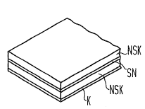
Figure 1 is a diagram oE the ~andamental construction of a
laminate for a shrinkable sleeve corresponding to the invention.
This ~igure illustrates that the shrinkable component SN is embedded
between two non-shrinkable romponents USK and that a ~urther layer R
for example a heat-shrinkable adhesive, is applied to one side. When
heat is supplied up to the shrinkage temperature of the heat-
shrinkable component SN, the non-shrinkable components NSK soften
without melting or even running, so that the shrinkage forces of the
shrinkable component SN can fully develop and the sleeve can shrink
onto the encased object. The applied fusion adhesive K melts and
produces the seal between the sleeve and the encased object.
Following cooling a sealed connection is established.
Figure 2 is a diagram of an exemplary embodiment of a
shrinkable component S~ in the form of a reticle having rhomboid
cells. As already described, the individual reticle fibre elements
SNFl can be considered as shrinkable elements which may be embedded
in the sleeve in stretched or unstretched form. These reticle fibre
elements SNFl ar~ permanently connected to one another at the
respective intersection points KP so that a s~able structure is
formed. This causes the shrinkage forces of the individual reticle
fibre elements SNFl to be uniformly distributed over the entire
surface area. In this way scarcely any tension occurs which could
lead to unintentional deEormation. The actual structure of the
reticle cells NMl is not important; rectanqular, curved or similar
basic shapes can be selected, bot the ixing at the individual
intersection points must be provided. A reticle structure
corresponaing to figure 2 can be produced, for example, in a simple
manner as a moulded component in the form of a mat which, following
the cross-linking, either immediately or together wlth the other
layers ls stretehed and thus forms the shrlnkable component SN. On
-
- -: : , . . , -
.
!
.
~23~7
the basis of the simple construction of such a shrinkable structure
it is possible tc shape the shrinkable reticle before incorporation
into a shrinkable component which then, in the finished component,
may result in a shrinkage only in predetermined sub-æones. This
mean~ that sleeves can be produced which are shrinkaole only in the
required zones, whilst the other zones are not influenced by the
shrinkage. This design is not possible with conventional heat-
shrinkable fabrics.
Figure 3 illustrates another embodiment of a shrinkable
component SN2 in the form of a curved reticle. Here the reticle
consists of individual reticle fibre elements SNF2- which are
generally parallel, and each fibre is fixed to its immediate
neighbours at alternating points along its length. When this
"parallel structure" has been extended in the transverse direction,
the lattice formation shown in figure 3 is produced, the individual
reticle fibre elements SNF2 of which are joined to one another and
fixed at the "intersection pointN RP for example by material
welding. A reticle of this kind is particularly flexible and,
depending upon requirement, can be introduced more or less closely
into the other layers~ i.e. in this way the degree of shrinkage and
the level of the shrinkage forces, as regards the overall structure,
can be varied within certain limits. Similar effects can al50 be
achieved by placing additional reticle layers at predetermined areas
as the shrinkage is intensified in these multi-layer zones.
Finally figure 4 is a diagram of a sleeve SU in the form of
a heat-shrinkable sleeve which is constructed from the described
individual elements. The described layers, the shrinkable component
SU and the non-shrinkable components NSK are arranged in the central,
shrinkable zone of the shrinkable sleeve SU. In additlon an adhesive
layer K is applied to that side o~ the sleeve which later faces
inwards. The edge zones R8 along the shrinkable sleeve SU consist of
sealing elements or at least are prepared in such manner that such
elements can be inserted or applied. However, these edge z~nes R~
must be heat-resistant at the shrlnkage temperature, i.e. at this
temperature they must retain their shape. This can be achieved, ~or
~ 323~77
example, by strong cross-linking of these edge ~ones RB.
Corresponding heat-resistant linings are also suitable for this
purpose. Furthermore, by means of a longitudinal extension of such
an edge zone on the inside of the sleeve a proiection can be formed
which, when the sleeve is closed, bridges the longitudinal gap and
forms a seal. The edge zones RB can be designed in accordance with
any known sealing system, such as for example a wedge seal with a
bar. However, this has no direct influence on the design of the
shrlnkable part of the sleeve.
~,
: ' :
::
' , ,
'
,
.