Note: Descriptions are shown in the official language in which they were submitted.
1 323542
ZSll
METHOD AND APPARATUS FOR STORING, DISPENSING AND
APPLYING SURGICAL STAPLES
In recent years various forms of surgical
stapling tools have been introduced to surgeons
and others in the medical treatment community.
Experience with these tools has shown that
although stapling tools are often a great
improvement over prior suturing techniques, the
tools have exhibited shortcomings that should be
addressed in newer tool designs.
For example, many surgeons have found that
in using a stapling tool it is preferable to
partially dispense and crimp a staple, so that the
staple extends from the tool and the placement of
the staple points can be visualized easily. This
action requires that the tool is capable of
partially forming the staple and retaining the
staple in that disposition. Unfortunately, some
surgical stapling tools cannot perform this
function, due to the fact that a partially formed
staple is held too loosely in the tool jaws to
permit effective placement of the staple in the
partially formed configuration. In other tolls,
interruption of a dispensing cycle can cause the
tool to initiate a new dispensing cycle, resulting
in jamming of the mechanism.
Also, surgeons demand a tool that is
jam-proof and trustworthy; obviously, a tool that
fails during surgery creates delays and
frustrations that are aggravating, costly,
potentially dangerous, and completely
unacceptable. Many prior art surgical stapling
tools have complex mechanisms involvlng many
:: - ~ : .
"
1 323542
ZSll
--2--
components, close tolerances, and critical
engagements. Factors such as thermal dimensional
changes, causal impact to the tool, or erratic
manufacturing techniques can cause prior art tools
to jam and fail.
A further criticism of prior art tools
involves their "feel" and ease of use. The feel of
the tool is an intangible quality that involves
such factors as the ability to visualize the
staple placement, the mechanical advantage of the
tool mechanism, the relationship between manual
movement and progress in the staple dispensing
cycle, the smoothness of actuation of the
mechanism, and the like. Also, some mechanisms
require a "pre-cocking" motion, before each
dispensing cycle, that can introduce an awkward
manipulation into the use of the tool.
The present invention generally comprises a
method and apparatus for storing, dispensing, and
applying surgical staples. The apparatus includes
a pistol-like tool having a handle portion with a
manually movable trigger lever, and a rotating
barrel portion with a staple track for storing
staples in parallel, stacked, column fashion, the
axis of the column extending generally colinearly
with the barrel axis. Thus the barrel also
services as the cartridge for holding the staples.
The staples are urged distally in the track by
spring means, and the distal track portion is
curved out of axial alignment so that the distal
staples are gradually urged into points-first
alignment as they traverse the curved portion. A
form tool is slidably disposed in the barrel
portion and adapted to advance past the distal end
of the staple track and urge the distal-most staple
.
:~ .
1 323542
ZS11
--3--
against a fixed anvil tool to crimp the staple.
The form tool includes a drag spring which engages
the distal-most staple in the staple track as the
form tool retracts after a crimping cycle, pulling
the distal-most staple from the track into a
dispensing position for the next dispensing cycle.
The tool includes a drive track oriented
parallel to the barrel axis and located within the
proximal end of the barrel, and a drive block
connected to the form tool and the trigger lever
and mounted for reciprocal translation along the
drive track as the trigger is actuated. The drive
block includes a pawl engaging ratchet teeth .
formed in the drive track and oriented to prevent
proximal translation of the block and the form
tool. The trigger is pivotally mounted in the
handle, and the inner end of the trigger includes
gear teeth that engage like-formed teeth in the
drive block in rack-and-pinion fashion. The pawl
includes a release slide actuated by translation
of the block to the distal end of the drive track,
coincident with full distal translation of the
form tool and crimping of the dispensed staple,
the release slide disengaging the pawl and
allowing the drive block to be returned proximally
by resilient means. The rack and pinion drive
engagement of the block and form tool, together
with the ratchet teeth engagement, permit the
dispensing cycle to be interrupted at any degree
of trigger actuation with the dispensed staple
firmly retained in its position.
The tool also includes a counter assembly,
disposed within the proximal end of the barrel
portion, for indicating the number of surgical
staples remaining to be dispensed from the tool.
,
'
1 323542
ZS11
-4-
The counter assembly includes a pair of
concentric, nested wheels having indicia formed
about the outer surface thereof and ratchet teeth
formed on the outer edges thereof. A counter pawl
extends from one surface of the drive block to
engage the counter ratchet teeth at the proximal
end of each reciprocation of the drive block. One
wheel bears units indicia, and the other bears
tens indicia, and the appropriate indicia are
visualized through a counter window in the
proximal barrel portion.
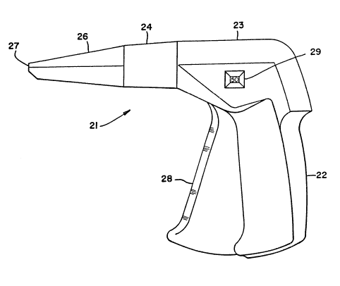
Figure 1 is a side elevation of the tool of
the present invention for storing, dispensing, and
applying surgical staples.
Figure 2 is a front end elevation of the
tool shown in Figure 1.
Figure 3 is a side elevation of one housing
portion of the handle and proximal barrel portion
of the tool of the present invention.
Figure 4 is a side elevation of the other
housing portion of the handle and proximal barrel
portion of the tool of the present invention.
Figure 5 is an enlarged, detailed view of
the counter assembly placement within the housing
portion shown in Figure 4.
Figure 6 is an enlarged, partially
cross-sectional view of the drive block mechanism
of the present invention, shown at its distal
limit of translation.
Figure 7 is an enlarged, fully
cross-sectional view of the drive block mechanism
of the present invention, shown in its proximal
position.
:, .
.
.
1 323542
ZS11
--5--
Figure 8 is an enlarged cross-sectional
view of the drive block mechanism, taken along
line 8-8 of Figure 6.
Figure 9 is an enlarged, cutaway view of
the drive block track and ratchet teeth of the
present invention.
Figure 10 is a plan view of the drive block
mechanism and its engagement with the counter
assembly of the tool of the present invention.
Figure 11 is a plan view of the stop slide
member of the drive block mechanism, as shown in
Figures 6, 7 and 10.
Figures 12-14 are a sequence of views
depicting the actuation of the counter assembly by
the counter pawl of the drive block mechanism.
Figure 15 is a cross-sectional view of the
wheel assembly of the counter assembly, taken
along line 15-15 of Figure 12.
Figure 16 is an exploded view of the
rotatable barrel assembly of the tool of the
present invention.
Figures 17-19 are a sequence of
cross-sectional views of the rotatable barrel
assembly, showing the actuation of the form tool
and advancement and dispensing of a surgical
staple.
Figure 20 is a bottom view of the assembled
components of the dispensing and crimping
mechanism of the tool of the present invention.
The present invention generally comprises a
method and apparatus for storing, dispensing, and
applying surgical staples for suturing wounds,
incisions, and the like. With regard to Figures 1
and 2, the apparatus comprises a tool 21 having a
pistol-like configuration, with a handle portion
,, . : , :
' ' ' ~
~ , :
1 323542
ZS11
--6--
22 and a barrel comprising a proximal barrel
portion 23, a medial barrel portion 24, and a
distal barrel portion 26. The surgical staples
are stored within the barrel portion 26, and
dispensed and crimped at the distal end 27
thereof, as will be explained in detail in the
following description. A trigger lever 28 is
pivotally mounted in the portion 23 and disposed
to be squeezed by manual action in proximation to
the handle 22 to actuate the dispensing mechanism
of the tool.
With regard to Figures 3 and 4, the
portions 22, 23 and 24 of the tool 21 are formed
by a pair of housing members 31 and 32. The
housing members are preferably molded of durable
plastic material, and are formed with side walls
having generally identical conformations for
mating engagement therebetween. The side wall of
housing member 31 includes a plurality of pins 32
extending therefrom to engage corresponding holes
33 formed in the side wall of the housing member
32 to join the housing members in precise
alignment. The side walls also define cavities 35
in each housing member which are combined in the
assembled housing members to define an enclosed
space which supports and protects the mechanism
described below. The side walls together further
define a slot opening 34 through which the trigger
lever 28 extends from the handle portion.
A post 36 extends from the interior surface
of the cavity of the housing member 32, and is
received in a recess 37 formed in registration
therewith in the surface of the cavity 35 of the
housing member 33. The inner end portion of the
trigger lever 28 is provided with a hole 38
ZS11 1 323542
--7--
through which the pin extencls to secure the
trigger lever in pivoting fashion. The inner end
surface of the trigger lever is provided with a
plurality of pinion gear teeth 38 arrayed about a
radius generally concentric with the pin 36.
Confronting interior surface portions 41 of the
cavities 35 are recessed to define a linear drive
channel or track 41 extending generally coaxially
with the barrel portions 24 and 26. A drive block
42 is received and retained within the drive track
41 in freely translating fashion.
The drive block 42 is a critical component
of the present invention, in that it converts the
rotary motion of the trigger lever 28 to linear
translating motion to actuate the dispensing and
crimping mechanism of the tool, as described
below. The drive block 42 is provided with a
plurality of rack teeth 43 formed in confronting
engagement to the pinion teeth 38 of the trigger
lever, so that the drive block is driven
reciprocally in the drive track 41 by sc~ueezing
and releasing the trigger lever. Furthermore,
this drive engagement provides a constant
mechanical advantage, and permits virtually no
free play in the mechanism.
With regard to Figures 6, 7, 9 and 10, the
drive track is further provided with a plurality
of ratchet teeth 46 arrayed in linear fashion
along a portion thereof and directed toward the
distal end of the tool barrel. The drive block is
provided with a drive pawl 47 having several rows
of ratchet teeth 48 formed in complementary
fashion to the teeth 46 and disposed to engage the
teeth 46 to prevent proximal translation of the
drive block while permitting distal translation of
_.
:'
1 323542
ZS11
-8-
the drive block. The pawl 47 is mounted on a
pivot pin 49 on the drive block, and a spring 51
secured to the drive block biases the pawl into
engagement with the ratchet teeth 46. The ratchet
teeth 46 and 48 are of extremely fine pitch, so
that proximal free play motion of the drive block
is substantially eliminated.
The drive block further includes a channel
52 formed in the upper surface thereof and
extending generally colinearly with the barrel
axis. The channel is disposed directly adjacent
to the pawl 47 and the pivot pin 49. A slide
member 53 is received in the channel 52 in freely
translating fashion, and is provided with a
ramped, camming surface 55 at the proximal end
thereof that is disposed to impinge on the pawl 47
as the slide member translates proximally with
respect to the drive block. The slide member
further includes a pair of tabs 54 extending
laterally from the distal end thereof. The drive
track 41 includes a foreshortened auxiliary track
56 in which the tabs 54 translate as the drive
block is translated by the trigger actuation. The
track 56 is dimensioned in the axial direction so
that as the drive block is translated to approach
the desired limit of distal travel, the tabs 54
strike the end of the track 56 and stop the slide
member, causing the slide member to translate
proximally with respect to the advancing drive
block. The proximal camming surface 55 impinge
on the pawl 47, pivoting the pawl about the pin 49
and disengaging the ratchet teeth 46 and 48. The
drive block is thus freed for retrograde motion in
the proximal direction when the trigger lever is
released. As the drive block translates
.
::
1 323542
ZS11
_g_
proximally to the end of the drive track 41, the
proximal end of the auxiliary track is engaged by
the tabs S4, causing the slide member to translate
distally with respect to the drive block and
return to its initial distal disposition for the
next dispensing cycle. The pawl is thus released
by the slide member, and is urged by spring 51 to
re-engage the ratchet teeth 46.
The medial and distal barrel portions of
the tool of the present invention are defined by a
pair of axially extending barrel housing members
61 and 62, shown in Figure 16. The housing
members 61 and 62 define the distally tapered
outer configuration of the barrel, and are
provided with confronting side walls disposed for
complementary fit to form a smoothly contoured
outer assembly. The members 61 and 62, which are
preferably molded of durable plastic material, are
provided with semi-cylindrical proximal end
portions which together define a cylinder
dimensioned to be received within the bore 60
defined by the housing members 31 and 32 (Figures
3 and 4). An annular flange 45 extending radially
outwardly from the proximal end of the assembled
housings 61 and 62 is dimensioned to be received
within an annular groove 50 at the inner
(proximal) end of the bore 60 with sufficient
clearance to permit free rotation of the barrel
portion about the barrel axis, yet retain the
barrel assembly to the assembled housings 31 and
32.
The barrel assembly also includes interior
features and surfaces which are integral
components of the staple storing, dispensing, and
crimping mechanism of the tool. For example, a
. ~
1 323542
ZSll
--10--
pair of axially extending, laterally space slots
63 are formed in the interior of housing member 62
to comprise a staple track for storing a large
plurality of surgical staples 64. The staples are
stored in a parallel, stacked column 65, with the
webs and legs of adjacent staples impinging in
parallel relationship to provide the most
volumetrically efficient staple storage. A staple
pusher 66 is translatably received in the staple
track, and is provided with a pair of pusher tabs
67 which impinge on the proximal-most staple in
the track. A compression spring 68 is also
received in the housing 62 to resiliently urge the
staple pusher distally and apply constant force to
the staple column.
It should be noted that the staples 64 in
the column 65 are not adhered nor joined to each
other, but are maintained in their column
configuration by the compressive force of the
pusher 66. With regard to Figures 17-19, a salient
feature of the invention is that the distal end of
the staple track is provided with a non-linear
portion 71 curved out of the plane defined by the
webs of the staple column in the linear track
portion, so that the staple legs fan out as the
staples traverse the track portion 71. Indeed,
the staples are gradually rotated in track portion
71 from their column orientation, in which the
staple legs are transverse to the barrel axis, to
a points-first orientation in which the staple
legs are parallel to the barrel axis. It should be
noted that the pusher tabs 67 of the staple pusher
66 are provided with serrated portions 72 so that
the tabs 67 may be sufficiently flexible to tra-
verse the curved track portion 71. Thus the staplepusher is capable of delivering all the staples in
1 323542
ZS11
the storage track to the dispensing and crimping
portion of the tool. Even the proximal-most staple
in the track is held in position by the tabs 67
prior to its engagement by the drag spring, as
described below.
Also secured within the barrel housing
assembly 61-62 is a track cover panel 73 which
secures the staples 64 and pusher 66 in the staple
track. The distal edge 74 of the cover panel 73
is rounded to accommodate the curved track
portion 71. The housing members 61 and 62 also
define a channel in which a form tool 76 is
disposed for translation parallel to the axis of
the barrel. The form tool comprises an elongated,
planar web having a notch 77 formed in the distal
end thereof to define a pair of staple-engaging
lands 78. The lands 78 are spaced to engage
laterally opposed end portions of a staple web,
and are further provided with a pair of laterally
extending grooves formed in the respective end
surfaces thereof to engage the staple web. The
proximal portion of the form tool is provided with
a rectangular hole 79 extending therethrough and
disposed to receive a guide post 81 extending from
the housing 61. The post 81 acts as a stop to
limit the proximal and distal translation of the
form tool, as well as to mount a compression
spring 70 disposed between the post 81 and the
proximal end of the slot.
The proximal end of the form tool is also
provided with a coupling member 82 secured
thereto. The coupling member includes a disk 83
dimensioned to be received within a slot 84 provided
in the distal end of the drive block 42, as shown
in Figures 7 and lO. The disk is freely rotatable
in the slot 84, so that the barrel assembly may be
1 323542
-12- ZSll
rotated about the barrel axis while the form tool
remains mechanically connected to the drive
block. It may be appreciated that reciprocal
translation of the drive block caused by trigger
actuation and release results in like reciprocal
motion of the form tool.
Another component of the dispensing and
crimping mechanism is a finger spring 84, which
comprises a planar web member resting on one
surface of the distal end portion of the form tool
and disposed to translate axially in the barrel
and independently of the form tool. The finger
spring includes a pair of resilient fingers 86
extending distally therefrom and spaced laterally
approximately the same amount as the lands 78.
The web portion of the finger spring is provided
with a rectangular hole 87, and a lug 89 extends
from the form tool through the hole 87 to link the
translational motion of the two components
together, as will be explained below. When the
form tool is in the retracted (proximal) position,
shown in Figure 7, the fingers 86 extend slightly
distally of the lands 78 to define a gap 80
therebetween dimensioned to receive and retain the
web of a staple 64.
The crimping mechanism also includes an
anvil member 88 secured fixedly to the distal
interior surface of the barrel housing 61. The
anvil member include a shank 89 extending axially
and distally therefrom and terminating in an anvil
90 extending transverse to the barrel axis. An
ejector spring 91 is secured fixedly between the
anvil member and the interior of the barrel
housing 61, and included a pair of resilient arms
92 extending distally therefrom. The arms 92 are
,
--` 1 323542
ZS11
-13-
spaced apart laterally to straddle the anvil and
shank, and are spaced slightly inwardly of the
fingers 86.
At the distal end of the barrel housing
assembly, a slot formed therebetween defines a
linear feed path 93 in which the staples 64 are
serially dispensed, crimped, and ejected from the
tool. It may be noted, with regard to Figures
17-19, that the anvil projects into the feed path
93, and the fingers 86 and the ejector arms 92
also project into the feed path 93. In the
initial quiescent position, shown in Figure 18,
the form tool 76 and the finger spring 84 are
retracted to their proximal position, and the web of
a staple 64a is retained therebetween. As the
trigger lever 28 is squeezed and the drive block
42 translates distally, the form tool is likewise
translated distally. The lands 78 of the form
tool impinge on laterally spaced portions of the
web of the staple 64a, pushing the staple 64a past
the fingers 86 and toward the anvil 90. The
fingers 86 bend resiliently to release the staple
64a, as shown in Figure 19. The web of staple 64a
then encounters the arms 92 of the ejector spring,
which impinge on the staple web and frictionally
resist any further distal translation thereof.
As the form tool advances farther distally,
the advancing staple and the form tool itself urge
the ejector arms to bend resiliently out of the
feed path. The medial portion of the web of
staple 64a impinges on the anvil 90, while the
laterally opposed portions of the staple web are
drivèn past the anvil by the lands 78 of the form
tool, as in Figure 19. It should be noted that
the notch 77 of the form tool is dimensioned to
' ' ~ '~' ' : `
: : '
1 323542
ZS11
-14-
receive the anvil 90 therein. The lands 78 thus
cause the staple web to bend about the anvil to an
angle of approximately 90 , bringing the points of
the staple legs into confronting, spaced apart
opposition. The staple 64a thus becomes crimped,
securing together the tissue into which it is
directed as the process described above takes
place.
It should be noted that the dispensing and
crimping process can be interrupted at any point
by the user of the tool, merely by halting manual
squeezing of the trigger lever 28. The form tool
cannot retract proximally, due to the action of
the ratchet teeth 46 and 48, and the staple 64a is
initially retained between the lands 78 and the
frictional engagement of the ejector arms 92.
After the ejector arms are driven out of the feed
path by the advancing staple, the staple web is
pinched between the anvil and the lands, and is
likewise firmly retained in position if the
crimping process is halted. Thus the present
invention facilitates a preferred method of
surgical staple application, in which the staple
legs are extended from the distal tip of the
barrel and partially crimped, after which the
points of the staple are carefully placed in the
tissue and the crimping process is completed.
The components of the tool are dimensioned
and arranged so that just prior to full distal
translation of the form tool 76 and crimping of the
staple 64a there is actuation of the slide 53 and
release of the pawl 47. Release of the trigger
lever causes resilient force to be applied by
spring 70, which is compressed during proximal
advance of the form tool, so that spring 70 urges
,
. . .
':
~. . :
: . :;
1 323542
ZS11
-15-
the form tool to retract proximally. As the form
tool retracts, the ejector arms 92 are freed to
return to their quiescent position in the feed path
93, as in Figure 17. The ejector arms thus urge
the web of staple 64a to slide out of engagement
with the anvil 90, releasing the crimped staple
from the tool. Thus staple release is
accomplished without any manipulation of the tool,
other than release of the trigger lever.
After further retraction of the form tool,
the distal end of the form tool clears the fingers
86 and permits the fingers to re-assume their
quiescent position in the feed path 93. The
engagement of lug 89 in hole 87 defines a gap 80
between the fingers 86 and the lands 78, the gap
80 being dimensioned to receive the web of the
next staple to be dispensed. As the form tool and
the fingers retract proximally together past the
outlet of the curved staple track portion 71, the
resilient pressure of the staple pusher 66 causes
the web of the distal-most staple in the curved
track portion to slide into the gap 80 between the
fingers and the lands, as shown in Figure 17.
Further proximal translation of the form tool and
finger spring pulls the captured staple from the
staple storage track and places it in the feed
path 93, as shown in Figure 18. The dispnesig
mechanism is thus reloaded for the next dispensing
cycle.
It should be noted that the staple track
portion 71 includes a lip 94 past which the points
of the staple are translated as the staple web is
captured and pulled from the track portion 71.
After the staple points clear the lip and the
staple enters the feed path 93, the legs of the
1 323542
ZS11
-16-
captured staple cannot return past the lip because
the next distal staple impinges on the legs of the
captured staple, as shown in Figure 18. Thus the
captured staple is directed only along the feed
path.
A further unique feature of the tool of the
present invention, shown in Figures 5 and 12-14,
comprises a counter to indicate the number of
staples remaining in the tool. With reference to
Figure 5, the interior of the housing member 32 is
provided with a cylindrical recess 96 located
between the trigger pivot pin 37 and the drive
track 41, with the display window 29 extending
from the recess 96 to the exterior of the tool.
A cylindrical pin 97 extends concentrically from
the recess 96, and a rectangular extension 98 of
the recess extends radially outwardly therefrom.
A counter wheel 99 includes an annular groove 101
extending in one face thereof, and a counter wheel
102 is received in the groove 101, as shown in
Figure 15. The wheels 99 and 102 are provided
with serial numerical indicia formed on and arrayed
about adjacent respective surfaces 103 and 104
thereof. The wheels are received in the recess
96, and wheel 99 includes a central bore
dimensioned to receive the pin 97 therethrough.
Portion of the indicia on the surfaces 103 and 104
are displayed through the window 29.
The wheels 99 and 101 are both provided
with ten ratchet teeth arrayed equally about the
peripheral edges thereof. The ratchet teeth 106 of
the wheel 99 are closely adjacent to the ratchet
teeth 107 of the wheel 102, due to the nested rela-
tionship of the wheels. Furthermore, one of the
teeth 108 of the array of teeth 106 on wheel 99 is
provided with a root portion extending radially
: : . :- :- :::
: . ., . :- . ~ - :-
.. . . ..
1 323542
ZSll
-17-
inwardly further than the other teeth 106. It
should be noted that the ratchet teeth 106 are
spaced slightly radially outwardly of the teeth
107, even though the indicia 103 of wheel 99 are
spaced radially inwardly of the indicia 104. As
shown in Figures 12-14, the indicia 103 comprise
numerals one through nine, representing unit
numbers, and the indicia 104 comprise numerals one
through five, representing tens of units. A stop
spring 109 is received in the rectangular recess
99, and arranged to extend to and engage the
ratchet teeth 106 to prevent counterclockwise
rotation thereof, as seen in Figures 12-14.
The drive block 42 is provided with a
counter pawl 111 extending therefrom and arranged
to impinge on the nested counter wheels as the
drive block translates proximally to its quiescent
position in the drive track 41. The counter wheel
are arranged so that the initial impingement of
the pawl 111 on the wheels engages the deeper root
of ratchet tooth 108, permitting the pawl to also
engage one of the teeth 107 of wheel 102. As a
result, the first impingement of the pawl on the
wheels rotates both counter wheels, decrementing
both the tens and units indicia displayed in the
window 29, as shown in the transition from Figure
12 to Figure 13. Thereafter, the subsequent
proximal return of the drive block causes the pawl
111 to engage the next ratchet tooth 106, which is
not sufficiently deep to permit engagement of the
teeth 107. Thus the wheel 99 is decremented by
one unit indicia for each proximal return of the
drive block. After ten decrements of the wheel
99, the ratchet tooth 108 has rotated fully about
the wheel, and is positioned to be engaged again
.
1 323542
-18- ZS11
by the pawl 111. The wheel 104 is thus again
decremented by the subsequent drive block return,
so that the counter display is decremented
serially from the initial setting (fifty, in the
preferred embodiment) to zero.
It may be appreciated that the present
invention provides a superior tool for storing,
dispensing, and applying surgical staples. The
mechanism of the tool is extremely simplified,
utilizing a minimum of moving parts, so that the
tool may be economically produced for disposable
after one use. The action of the mechanism is
smooth and continuous, and jam-proof. The barrel
may be rotated to any angle for dispensing and
applying staples without affecting the action of
the mechanism whatsoever. And, the dispensing
cycle may be interrupted at any point without
adversely affecting or jamming the mechanism, so
that a staple may be partially dispensed and
crimped before it is placed in tissue and
subsequently fully crimped.
,