Note: Descriptions are shown in the official language in which they were submitted.
1324~3~
DIC--526
DISPI.AY POR MODllI.aR DIC~TI~N/TRANSCRI~>TIO~ SYSl~
EIACRGROUND OF T~E INVE~TION
This invention relates to dictation/transcription
systems for the recording and retrieval of audio signals such
as voice signals and, more particularly, to a display device
for a dictation/transcri~tion system for display of
information relating to the usage of a recording/pl~yback
unit.
A ~ariety of display devices for
dictation~traDscription e~uipmant is presently available,
sucb as lamps, IED's, liquid crystal displays and the li~e.
By way of exa~ple of display devices for
di~tation/transcription eguipment which have been proposed,
the followi~g ~nited States Patents ase of interest~
NatisoD tU.S. Patent No. 4,200,893) discloses the
display of locations of infosmation recorded on a tape ``
recording medium, and a counting of re~olutions of a reel of
a tape traDsport to determine position of the recording tape.
Sander et al ~U.S. Patent No. 4,319,337) disclose the
ctorage and display of information relating to the length and
identity of recoraed messages in a syste~ employing multiple
di~t~tion stations.
Titus et al (~S. Patent No. 4,398,279) disclose a
numerical readout of dictation segments and time available
for dictatio~ on ~ recording medium.
Titus et al (~.S. P~tent No. ~,399,527) disclose the
u8e of registers for storing information as to the location
of messages recordea on a recording medium, and the
presentation of sucb information by numerical and graphical
display~.
Dictation/transcription eguipment may be employed in a
business office for dictation of memoranaa, letters, and ``
other sucb materials w~icb are later played back for
transcription to a typewritten document. Typically,
:.,
- 2 ~ 1 324436
dictation is recorded on cassettes of magnetic recordiDg
tape; and a give~ cassette may store several i~ems of
dictation Of di$ferent types, of differing length, by
different authors, and baving different priorities of
transcrip~ion.
Reret~f~re. detailea information ab~ut the l~cation of
a dictated item on the recording tape, the length of that
item, its author, the priority in whicb each item should be
transcsi~ed, and other suc~ relevant dictation/transcription
informa~tion has not been available readily to the
transcriptionist. It would be advantageous if such
informatiQn is recorded for display. In some
dictation/transcription machines baving electronic displays,
information belpful to the transcription of recorded material
may be lost tor ~erased~) upon shut down or power de-
energization of the macbine.
SI~IARY OF TElE INVENTION
The foregoing problems are overcome and other
ad~antages are ~ttained in a dictation/transcription system
of the present invention which includes a display device that
displays information relating to recorded dictation,
including the location of a recorded message, the length of
that message, identification of the author, time, date, etc.
T~e display presents a graphical portrayal of the
locations of recorded messages by means of, for example,
three separate bar grap~s, one preferably formed of one or
more segments of visual indicators wbich, when energized,
displays represent`ations of the length of each o~ the
messages. The segments representing the length of a message
~re grouped in a ~bloc~, and the positions of the ~locks
represent the relative positions of the recorded messages.
Also displayed tpreferably by flashing of the segment blocks~
are representations of the type or nature of a message, such
~ a ~lett ~, ~priority letter~, or the like. One of the
~ar graphs preferably display~ a cursor which represents the
present position on the recording medium. Yet another bar
.
~ 3 ~ 132~3~
graph represents the locations ~f ~instructi~ns~ and ~notes~.
~lashing of segments inaicates ~priority~ and ~special~
notations. ~urther data, such as autho~ iaentification~
lensth of a recording tape, time, and date are presentea by
S alpbanumeric symbols.
~D accordance with the invention, the display device
may be formed integrally with a recordin~/playback device, or
may be ~dapted to operate in a modular system as a separate
module which can easily be connected to and disconnected from
a recording/playb~c~ module~
Preferably, both the display device and the
recording/playbac~ device are provided with microprocessors
and a communication lin~ which couples command signals and
control information signals between the modules, thereby
enabling t~e modules to cooperate in performing various
system functions relating to the recording and retrieval of
messages, aDd the display of information.
One aspect of the invention is the recording of useful
non-message data on tbe recording medium by storing a
co~plete ~istory of usage te.g., message type, location,
length, author, etc.) on the medium along with recorded
aictation. Nhen a recording tape such as a tape cassette is
u~ea, the recordea cassette takes on the attributes of an
~intelligent~ ~ssette.
ID ODe ~mbodiment, tape ~otion pulses are transferred
fro~ the recorainq/playback device via a communi~ation link
to the microprocessor in the di~play device, the latter
opating in accord~nce with ~ programmed routine to attain a
lin~ar representation of the present position of the
recoraing tape which, in turn, is ~ndicated by the cursor on
tbe display device.
During dictation of a message, successive segments of
one of the bar graph displays are energized. A cue signal, -`
~hich ~ay be geDerated by the operation of a button on a band-
3~ held microphone, interrupts the seguence of segments witb a
~blan~ ~pace (e.g., de-energized segment) to indicate the
end of a message ~uch as a letter or report. The cue signal
. .
- 4 - 1~2~436
also commands the microprocessor of the display device to
store in internal memory ~he point of initial dictation
of the first message and, also the point at which the
current message ended~ In addition, author
identification, date, tim~ and other related data (if
desired) are stored in internal me~ory. As a nature of
the present invention, all of this information is also
recorded on the recording tapQ alongside thQ recorded
dictation.
Preferably, this display data is recorded as FSK
tones. Later, upon completion of the use of the
recording tape, the operator may press a "finish" cue
button on the display device to command the
microprocessor to transfer all the display data from an
internal memory to the r~cording tapQ for recording as a
su~mary block of data~
In accordance with a preferred aspect of this
invention, the display data that is storQd in the
internal rQ~ory and that ~s recordQd on the recording
tap also repres~nts the type of ~Qssage that has been
racord~d~ Such ~ssag~-type data distinguishes between
~priority~ and regular l~ttQrs as well as betweQn
instructions and special noteJ.
In the ~ent that the display data is erased from
2~ the internal ~n~ory or the cas~ette is transferred to
anothQr systQ~, it can be r~generated simply by scanning
the tape. an operator may request such scanning by
pressing a ~display" button on the display device.
Advantageously, the tape may be scanned in the forward
direction or in the reverse (rewind) direction. During
scanning, the display microprocessor, via the
r cording/playback head assQmbly, effQctively "reads"
~hat-ver display data has beQn recordQd to construct a
display presQntation. Should the summary data block be
r~ad during scanning, the display presentation is
constructed, storQd and displayed immediately.
~Priority~ l~tters, ~instructions~ and the like are
, . .
_ 5 _ 132~4 3~
suitably identified and may be searched and accessed
directly for immediate transcription from the tape.
BRIEF DESCRIPTION OF THE DRAWING
The following description, taken by way of example,
is best understood in conjunction with the accompanying
drawings w~erein:
Fig. 1 shows a styli2ed view of a recording/playback
device adapted for interconnection with a modular display
unit in accordance with the present invention;
Fig. 2 shows the modular display unit of the present
invention coupled to a dictation/transcription device
comprising the device of Fig. 1 with a display module
connected thereto for providing additional functions
useful for dictation and transcription; --
Fig. 3 is an electrical block diagram of tbe modular ;
interconnected system of Fig. 2:
Fig. ~ shows one embodiment of a tone modulator that ~"
~ay be used in the display module of the present
invention;
Fig. 5 shows one embodiment of a tone demodulator
t~t ~ay be used in the display module of the present
invention; '`'
Fig. 6 shows an arrangemQnt of rQgions of recorded
audio signals and recorded display data signals on a
recording tape;
Fig. 7 is a flow chart representing a relevant
portion of the operation of the microprocessor included
in the recording/playback nodule of Fig. l;
Fig. 8 i8 a flow chart representing the relQvant
operation of the ~icroprocessor included in the
recording/playback ~odule to record and detect display
data in accordance with the present invention; and
Fig. 9 is a flow chart of the relevant operation of
the ~icroprocessor included in the display modulQ for
3S controlling the operation of and interaction with the ~ -
recording/playback module.
)( . "'
,' " .
6 1324436
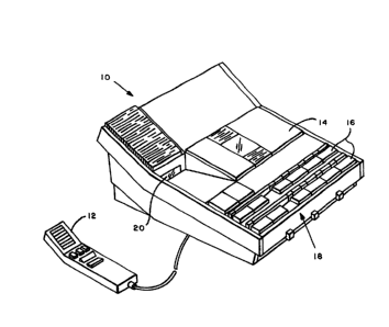
Wi~h reference to Figs . 1 and 2, there are shown,
respectively, a recordingfplayback device lo, and the
recording/playback device electrically connected to a
display device 22 incorporating the present invention.
These devices are more fully described ~n copending
application Serial No. 543,389, Filed: July 30, 1987,
Titled: NO W LAR DIC~ATIONJTRANSCRIPTION SYSTEM and
assigned to the assignee of the present invention. The
display device and the recording/playback device may be
o co~bined in a single unitary construction, or may be
constructed in modular form in which the
recording/playback device and the display device may be
connected to each other, and disconnected from each
other, as ~ay be desired to provide for a display of
recording-playback functions. By way of example, the `~
foll~wing description is directed to a modular form of
thQ recording/playback d~vice and the display device, it
being understood that the present invention is equally
applicable to a unitary construction of the ~-
recording~playback device and the display device.
The recording/playback device i8 shown in Fig. 1 as
~ Dodule 10 ~ic~ is operable as a stand-alone unit for
the recording and playback of sound, pareicularly voice.
A ~icropbone 12 is shown connected eO the module 10 for
~5 use by personnQl to record a spoken messaqe on a
recording ediu~ such as magnetic tape within a cassette
(not shown in Fig. 1) locaeed wiehin a compartment 14.
Push buttons 16 of a keyboard 18 are operably connected
~ith a tape transport (not shown in Fig. 1) for
advanc~oent and rewind of the tape. The module 10
lnoludes a display 20 which, for example, provides a
num rical read-out of present position of the tape.
Fig. 2 shows a display modulQ 22 which may be
connQcted to the recording/playback module 10 to present
additional information relating to dictation and
eranscription functions. For example, the display module ~`
22 presenes a plurality (preferably three) of bar graph
,"~
1321~36
displays co~posed of individual segments of visual
indicators such as LED's, LCD's or the like which appear
as display 24. Preferably, the display 24 is constructed
as a liquid crystal display (LCD), with the
5 aforementioned segments appearing as dark segments on a
light background though, if desired, the display may
present the segments as lighted segments on a dark
background.
successive segments form blocks which have lengths
proportional to recorded messages such as letters, memos,
and reports. The segments in a block may be made to
flash to indicate a "priority" item which is to be typed
immQdiately by a tran~criptionist. Additional useful
information is presented in alphanumeric form in a region
28 on thQ right side of the display 24, such as the ~ `
ideneificaeion of t~e author who dictated a message and
the length (in minutQs~ of the message. The date and
ei~e of messagQ is displayed in the display 20 of module
10. .
Fig. 3 is a block diagram of elQctrical circuitry of
t~e two ~odules 10 and 22. The recording/playback module
10 co prises a drive 46 for rotating a supply reel 48 and
a take-up reel 50 to transport a magneeic recording tape
52 past a recording/playback head 54 for the storing and
2S rQtrieval of audio and display data signals on the tape.
The ~odule 10 further comprises a recording circuit 56
and a playback circuit 58 which connect with the head 54, `
and a rotation detector 60 which is positioned alongside `
the supply reel 48, for example, for detecting rotation
thereof. A capstan 62 is operated by the drive 46 for
aintaining a constant speed of travel of the tape 52
during record and playback operation. As the tape 52
unwinds from the supply reel 48, the effective diameter
of the supply reel 48 becomes smaller causing its
rotational speed to increase in view of the constant
linear speed of the tape 52 driven by the capstan 62.
Therefore, the detector 60 detects a continuously
- 8 - 132~3~
increasing rate of rotation during forward motion of the
tape 52
As shown in Fig 3, the connection of the microphone
12 to the module 10 is accomplished via the interface
unit 66, the connection being shown as a set of lines
including a line for the cue signal, a line for voice
communication, and a line for signals controlling
transport motion such as forward, fast-forward and fast-
rewind The voice line from the microphone 12 is
lo understood to include conductors for transmission of
signals from the microphone to the recording circuit 56
and for playback of signals from the playback circuit 58
via a small speaker (not shown) within the microphone 12
The cue signal line activates an oscillator 176 to
generate the cue signal which i~ supplied via the
recording circuit 5c to the head 54
The recording/playback module lo also includes a
microproces-Qor 64, which applies control signals via an
interface unit 66 to ~he display 20, the drive 46, the
recording circuit 56 and the playback circuit 58
Rotation signals in the form of motion pulQes are
produced by the rotation detector 60, and are coupled via
t~ interface unit 66 to thQ microprocessor 64 ~ memory
68 couplod to the microprocessor 64 stores program data
~5 and ot~er inforoation useful in the operation of the
~icroprocessor 64
Digital signals are coupled between the interface
uni~ 66 and t~e ~icroprocessor 64 by a data bus 70 The
intorface unit also supplies signals from the keyboard 18
(partially s~own in Fig 3) to the microprocessor which,
in turn, controls display 20 and selects the operational
functions of the ~odule 10 and also of the module 26
A ~finish~ pusbbutton 72A on the display module 22
provides a signal indicating that an author ha~ finished
3S hi- dictation This signal initiate~ an operation in the
modules 10 and 22 by whicb a complete history of the
types of recorded messages, their locations, and their
X '. ' '
1324~3g
- 8a -
author(s) are recorded on the tape 52 as a digitally
formatted message placed alongside the audio information,
or dictation, that also is recorded on the tape. Another
pushbutton 72B on the display module 22 may be activated
by an operator to command the display module 22 to
display t~is recorded history on the display 24,
preferably in bar graph form as mentioned above.
In a preferred embodiment of the invention, the
presentation on the display 24 develops as the author
dic~ates into the microphone 12 and tape 52 advances.
One segment of the bar graph display is energized by way
of example, for each 30-second interval of dictation. A
graph length of ten segments would indicate, in the
foregoing example, a dictation time of five minutes. The
author
. ^ . . . .. .
, . .
- g- 132443~
indicates the end of a dictated passage, mem~ ~r report by
pressing a cue button on the microphone 12. This end-of-
dictation is represented ~y tbe omission of a segment (i e ,
the segment is not energized~ and the properly de-energized
5 segment is determined as ~ function of the number ~f motion
pulses that have been generated by rotation detector 60 of
the recording~play~ack module 10. Pressing the cue button
also activates the module~ 10 and 22 to store the end of
dictation point of the dictated material on the recording
tape 52, as well as the author's identification, point of
initial dictation, time and date of dictation of that
particular message. Also, when the cue button first is
acti~ated, the original starting point at which dictation on
the tape commenced is stored. This display data for all
1~ recorded messages is recorded on the recording tape 52 in the
form o~ a summary block of data in response to the operation
of ~finis~ ~utton 72A. At a later time, after a power
failure, for example, when modules 10 and 22 are subseguently
reactivated, or if the tape is transferred to another similar
system, the display module 22 can regenerate the graphical
display from the display data stored on the recording tape 52
upon command from the pushbutton 72B.
By way of example, the display data that is
transferred between modules 10 and 22 is in the form of a
~equence of audio tone signals. In order to produce and
recover tbese tone sig~als, the display module 22 includes a
tone modulator 74, ~ tone demodulatôr ~6 and a microprocessor
78, in addition to the aforementioned display 24 and a
~eyboard 26. The microprocessor ~8, which may be an NEC
Model 7S00, or ~imilar device, includes ~ memory 80 for
storing program data and the a~orementioned aisplay data.
A connector 40 interconnects the two modules 10 and 22
and comprises aD audio link composed of lines 82, 84 and 86,
and a digital data bus 88. The bus 88 couples digitally
formatted signals between the two microprocessors 6~ and 78.
The line 82 couples audio signals from the tone modulator 74
to the recordinq circuit 56. The line 86 couples audio
. . . . . : . . . -,
- 10 - 1324~3f~
signals from the playback circuit 58 to the tone
demodulator 76. The line 84 is a return line for the
signals on both lines 82 and 86. Analog switches so in
the form of field effect transistors (FET's) in the
recording/playback module lo, and analog switches 92 in
the form of FET's in the display module 22 permit either
of the modules 10 and 22 to be connected and disconnected
from the audio lines 82 and 84. The switches 90 are
operated by the microprocessor 64 via latches 94. The
switches 92 are operated by ~he microprocessor ~8 via
latches 96~ --
If desired, the audio link can be extended to enable
the connection of the audio lines of the display module
22 to a furt~er recording/playback module (not shown), ``
together with a concomitant extension of bus 88.
Thereby, tbe display module 22 may be adapted to function
with two recording/playback modules. In such adaptation,
a8 described in copending application Serial No. 543,388,
Filed: July 30, 1987, Titled: DISPLAY FOR MODUL~R
DICTATION/TRANSCRIPTION SYSTEM the memory 80 of the
display module 22 stores display data supplied from both
r~cording/playback modules.
Keyboard 26 of tbe display module 22 includes a hold
button 98, a CUQ select button 102, a FORWARD SEARCH
button 110 and ~ R~WIND SEARCH button 112. These buttons
ar~ electrically connected via line 104 to tbe
~icroprocessor 78 for selecting operating functions of
tbo microprocessor. Tbe bold button 98 is useful in
retaining a presontation on tbe display 24. The cue
select button 102 is useful during transcription because
it allows an operator to select a type of message to be
accessed 8uch a8 ~ letter, a ~priority" letter, an
in~truction or a "special" note. Recorded messages are
charactorized a8 one of the foreqoing types by operating
the cue buttons on microphone 12, and a specific cue
designation i8 recorded on the tape 52 (along with other
132443~
-- 11 --
data, such as the author's identification, point of
initial dictation, the date, the time, and ~he end point
of the message). In one particularly advantageous
embodiment of the display module 22, each message type
(or cue designation) may be selectively displayed (or
alternatively highlighted) along the bottom edge of t~e
display 24: and the cue designations are selected in
sequence by successive pushing of the cue select button
102~
When tape 52 moves past the head 5~, a cursor
indicating the tape position, moves along the display 24
in the hori20ntal direction to show the tape position.
The cursor may appear as a dark or light square
positioned beneath the array of segments of the "letter"
display graph on the display 24~
Infor~ation such as the author identification, the
date and the time of dic~ation can be entered by use of
two pus~buttons 106 and 108 referred to, respectively, as
the mode button and the select button on keyboard 26. If
desired, these buttons may be concealed from view and
fro~ inadvertent operation. The mode and select buttons
106 ~nd 108 ~re operatively connected via the line 104 to
the microprocessor 78 for entering and storing the
foregoing inforuation. Such information can be entered
2S conveniontly by pressing the mode button 106 successively
for selQcting author, id ntification, the date, and the
foru of ti~e ~12 hour or 24 hour clock) to be entered.
The selQct button 108 i8 pressed to cycle through the
nur~rals of the author identification, the time and date.
Thi8 data also is recorded from microprocessor 78 onto
tape 5~.
Further details of the circuitry of Fig. 3 will now
be described with reference to Figs. 4 - 6 followed by
tho flow charts of Figs. 7 - 9.
With roference to Fig. 4, the tone modulator 74
co~prises two oscillators 134 and 136, two switches 138
and 1~0, a digital inverter 142 and an OR circuit 144.
~''''`'"'
- ':
y~ .i,r~ ~ 3~o~
132443~;
lla
The OR circuit 144 comprises two summing resistors 146
and 148, and an amplifier lSO with a feedback resistor
152. In operation, the oscillator 134 produces a higher
frequency tone signal (e.g., 1800 Hs) and the oscillator
136 produces a lower frequency tone signal (e.g., 1000
Hz). These signals are
- 12 - 1 32~.~3~
coupled by the switches 138 and 140 to the OR circuit 144 t~
be outputted on the audio line 82 ( Fig . ~ ) as FSX ~ freguency
shift keying) signals. A diaital signal applied by the
microprocessor 7~ via line 156 to the switches 138 and 140
operates those switches to connect one or the other of
oscillators 134 and 136 to OR circuit 144. The inverter 142
provides for alternate operation of tbe switches 138 and 140
sucb that a logic-l signal on line 156 operates the switch
138 to output a ~ig~ frequency tone on line 82, and a logic-0
signal on line 1~6 ~perates t~e switch 140 to output a low
frequency tone on t~e line 82.
In the OR circuit 144, the summing resistors 146 aDd
148 couple signals respectively frcm the switches 138 and 140
to the negative input terminal of the amplifier 150.
~hereby, the modula~or 74 converts the digital signal on line
156 to audio tone ~SR signals on line 82.
~ig. 5 sbows details of tbe tone demodulator ~6, the
demodulator comprising a phase detec~or 158, a low-pass
filter 160, a voltage controlled oscillator 162, a comparator
16~, and a source 166 of a reference signal for the
comparator 164. The audio tone signal on line 86 (~ig. 3) is
applied to aD input terminal of the phase detector 158. The
comparator 16~ produces a digital signal which is applied via
line 168 to the microprocessor 78 t~ig. 3).
IA operation, the oscillator 162 oscillates at a
frequency dependent on the amplitude of a signal outputted by ` -
the filter 160 via line 170 to the oscillator 162. Tbe phase
aetector 158, tbe filter 160 and the oscillator 162 comprise
a phase-locked loop 172, the operation of which loop is well
~nowD. The detector 158 outputs a sipnal to the filter 160
having an amplitude proportional to a difference in phase
between the input signal on line 86 and an output signal of `~
the oscillator 162. The filter 160 integrates the output
signal of the detèctor 158 to provide a smoothly varying
signal OD line 1~0 for driving the oscillator 162. The
bandwidth of the filter 160 is set in a well-known fashion to
allo~ the loop 172 to follow the fre~uency of the audio tone
.
'
:
: ` . . , . . : , ,
1324436
- 13 -
line 86 as the tone frequency jumps between lower and
higher frequencies. The higher tone frequency represents
a logic-l signal and the lower tone frequency represents
a logic-0 signal for the transmission of display data.
It is noted that the frequency control signal on
line 170 increases in amplitude to provide the higher
output frequency of the oscillator 162, and decreases in ~-
amplitude to provide the lower output ~requency of the
oscillator 162. The signal on line 170 is applied to one
input terminal of the comparator 164, a reference signal
from the source 166 being applied to a second input
terminal of the comparator. The magnitude of the
reference signal lies between the two amplitude values of
the signal on line 170. The comparator 164 outputs a
logic-l signal in responsQ to a high output voltage on -~
line 170, and outputs a ;logic-0 signal on line 168 in
response to a low output voltage of the signal on 170~
~hereby, t~e demodulator 76 convQrts the audio tone FSK
signals on lino 86 to digital signals on line 168. A
digital tr~nsaission rate of, for example, 545 baud is
o~ploy~d in th~ prefQrrQd mbodiment of the invention.
Fig. 6 shows diagra~matic~lly a section of the
r cording tap~ 52. Portions of the tape carry recorded
audio signal~, while other portions of the tape carry ;;
recorded displ~y data for operation of the display 24 of
th~ display ~odule 22. While an audio portion of the
tape 52 ~ay be relativQly long, extending possibly
through al~ost the entire length of the tape, the display
d~ta portion i8 relativQly short.
The forward direction of tape ~ovement in Fig. 6 is
to~ard tho Ieft. It i8 seen that the display data is
recorded in a ~cue block~ after the corresponding audio
portion 80 a8 to include information as to the length of
th~t ~udio portion. The operator signifiQs his
conclusion of the dictation of a message (e.g., end of
l~tt r) by oper~ting a cue button to record a CUQ signal,
X ,., ~
. .
1324~6
- 13a-
which signal is recorded as a 15 Hz signal (for example)
on a region of the tape between the end of thQ audio
passage and the beginning of the corresponding cue block
display data portion.
` - 14 - 13~4436
During fast-~orward and fast-~everse moVement of the
tape 52, the 15 8z cue signal appears as a much higher
frequency ~ in the range of 150-450 Hz~ due to the rapid
motion of the tape. Nevertheless, the length of the recorded
portion of the cue signal is sufficient to allow the
record~playback module lo to detect the cue signal during
fast-forward and fast-reverse movement so as t~ enable the
drive 46 to stop the tape.
As shown in ~ig. 6, a summary re~ion is recorded in a
summ~ry data block at the end of the portion of the tape 52
contaiDing recorded information. ~he s~mmary data block
contains data summari2ing all of the dis~lay data recorded in
the previous data regions and, as has been noted hereinabove,
contains sufficient information to recreate the complete
presentation of the recorded messages on the display 24 of
the displ~y module 2~. The display data of the cue block
data regions and the display data of the summary datà block `
region ~re provided by the display module 22, as noted above,
upon ~n indication by the operator that he has completed
dictation of a message ~nd that he is finished with the
cassette, respectively. 2hese operator indicatlons are
provided by use of the cue button on the microphone 12 an~ by
use of the ~inish button on the keyboard 18.
As an example in the use of the display ~odule 22 for
prcsentin~ information useful in the transcription of
matcri~l from a previously recorded tape cassette, a
tr~nscriptionist m~y command the display module 22 to present
the above-aescribed bar graph display of the previously
recordea mesS~ges as follows: After insertion of a
previously rccorded cassette, the ope~ator pushes the
~display~ button ~2B on the keyboard 26 of the display module
22 to activate the microprocessor ~8 to read the information
provided in the su~mary data block of the tape 52 for
pre~entin~ the information on the display 24. The tape 52 is
then scannea in either forward or rewind directions,
aepending upon ~hether ~ORWARD SEARC~ button 110 or REWIND
SE~-RC~ pus~button 112 is actuated, to resd the stored
, .; ~ . . :
- 15 _ 1 3 2 ~ 436
.
information from the cue blockc of tape 52 into the
microprocessor ~8. If the ~display" pushbutton is actuated,
the summary data block is read first, and the entire disDlay
can be presented immediately, otherwise the display is
generated piecemeal as the display data of each cue block is
read. The operator selects the scan direction for accessing
the summary data block by, for example, a ~press-release~
operation of push~utton 72B to establis~ the rewind
direction, ~r a ~press-hold~ operation to establish the
forward directio~. During the scanning, the finish cue
signal preceaing t~e summary data block or end of message cue
signal preceding eac~ cue block is detected by a detector 178
IFig. 3), the detector 178 outputting a control signal via
the interfac~ unit 66 to the microprocessor 64.
During rewind scan, tbe microprocessor 64 responds by
directiDg the drive 46 to stop the tape when a 15 ~z cue
signal is detected, after which the tape is played in the
forward direction. This brings the summary data block or a
cue bloc~ past the head 5- for communication via the audio
2D lin~ to the to~e demodulator 76 and to the microprocessor 78.
During forward scan, the tape is ad~anced in the fast forward
mode and is brougbt to a halt in response to the detection of
a cue ~ignal. In ~iew of the fact that the tape may
overshoot tbe cue signal position and, consequently, miss a
part or all of the following display data portion, tbe
microprocessor 64 is progrummed to automatically command a
bac~-up of the tape transport by a preset amount which brings
the head 5~ behind the display data portion. Tbereupon, the
tape advances in the forward direction and the display data
is played bac~ to be outputted to the microprocessor 78 of
the display module 22. Thereafter, the microprocessor 78
co~mands the transport to advance further in the forward
direction to accumulate data of other ones of the cue blocks
of the tape 52, and finally to accumulate all of the display
data in the sum~ary data bloc~. In this way, information
relating to the messages recorded on a tape cassette is
presented to the modules 10 and 22.
_ .. . . . ... - ' ''
..
..
,, . , - : . . . :
1324~36
-- 16 --
The tape motion pulses generated by reel rotation
detector 60 are employed by the microprocessor 78 for
positioning the segments of the bar graph presentation.
The nonlinear relationship between reel rotation and tape
advance may be conver~ed to a linear relationship by
microprocessor 78 which employs a linearization procedure
of the type described in U.S. Patent 4,410,923, asQigned
to tbe assignee of the present invention, resulting in a
substantially linear presentation on the display 24. The
lo tape motion pulses are transmitted over the bUs 88 under
control of the microprocessor 64.
Fig. 7 is a flow chart of the overall function of
microprocessor 64 including a main loop 210 which
branches to block 226 of the flow chart shown in Fig. 8.
Block 226 (Fig. 8) begins the interaction between the
display module 22 and t~e recording/playback module 10.
Block 226 represents that the microprocessor of the
module 10 looks for a co~mand from the display module 22.
If no command is received, the operation reverts to the
~ain loop 210. If a display scan ~block 228) command is
received fro~ the display module 22, tho operation shown
in Fig. 8 continues to block 230 wherein the module lo
deitect~ whether the cue signal scanning i8 to be
acoo~plished in the forward or reversQ ~rewind) direction
of ~ove~ent of thei recording tape 52, depending upon the
op ration of the ~display~ pushbutton. If no display
scan co~mand from display module 22 is detected, the
operation proceeds to block 236 to detect a cue search
co~ and, whorein the module 10 operates the tape
transport to search the recording tape 52 for an end-of-
~ssago CUQ sign~l.
At block 230, the module 10 searches tape 52 in the
selected forw~rd or the rewind direction for a cue
signal. When a cue signal is detected (block 238) the
tape drive 46 stops the movement of the tape 52, and the
audio link i~ activated by operation of the switches 90
and 92 (block 240) for coupling signals played back from
- 17 - 1324436
the tape 52 to the display module 22. The tape transport
is operated to playback display data ~block 242) from the
cue block of the tape 52 to the display module 22
Playback continues until the end of the display data
5 (block 244) Nodule 10 then again receives a
forward/reverse command (block 246) and activates the
tape transport to search for the next cue signals The
cycle is repeated upon return to block 238 wherein the
module lo atte~pts to find the next cue block of the tape
52 containing display data
With reference again to block 244, if the end of
display data is not sensed but, rather, the end of
summary data ~recorded in a summary data block is
present, this end of summary data is detected at 248)
The tape 52 continues to move past the head 54 until all
of the summary data block is read from the tape for
transference to the display module 22 Thereupon, the
rodule 10 detects a stop co~mand ~block 250) indicating
the ~nd of the su mary data block, at which point the
tapo driv~ ~ is stopped and operation reverts to the
ain loop at block 210~
If the co~and from the display module i8 neither a
display scan co~oand nor ~ cu~ search command, the
received co~oand may be a cue record command Upon
detection of a cue record command, module 10 implements
the procedure for the recording of end of messaqe display
data or su D ary display dat~ previously accumulated
within the ~eoory 80 of the display module 22 This data
includes the locations of the start point of the first
mQssage (usually the beginning of tape) and the end
points of each message dictated on the tape, as well as~`
nes~age characterizing signals (such as a letter,
~priority~ lett r, an ~instructionn or a "special" note,
all of ~hich are displayed by respQctive, distinctive
3S displays) Also included are the identification of the
author, the date, and the time of r-cordlng If a ~ `~
- ~7a - i324~3~ ~
display scan command (block 228) is not detected, the
module 10 begins the procedure of transferring this
information from the memory 80 of display module 22 to
the summary data block or end of message region of the
S recording tape 52. The procedure is implemented by
activating the audio link 82 and record circuit 56 (of
Fig. 3~ at block 252, provided that a -
.
X ''~", '`, '
.,, :, .
:', :`
- 18 - 1 32~436
cue search command (block 236) is not received, but a cue
record command ~block 232) is detected. The sequence of
recorded information begins with the recording of the cue
signal ~block 254~ this being rollowed by the recording of
the display data ~block 256). The recording process stops
upon detecting a stop command ~lock 258) from the display
module 22, indicating that all of the display data has been
reaa from memory 80. Thereafter, the operation reverts to
tbe main l~op 210.
wit~ reference to block 236, if the command ~rom the
display module 22 is a cue search command to find a cue data
field on the recording tape 52, this is implemented by the
detection in bloc~ 260 of a forward or rèverse tape movement
command (e.g., a forward search or a rewind search command).
lS ~hereafter, ~t bloc~ 262, the module 10 may be provided with
a co~mand to advance to a specific location or to a specific
type of message on the recording tape. ~f no ~uch command is
given, the transport continues to advance the t~pe in either
the forward or reverse direction until a cue signal is
detected at bloc~ 26~. ~hereupon, playback of the cue data
field (typically, the cue block) coNmences as indicated at
bloc~ 266. If, at block 262, a specific location is
designated, then the drive 46 moves the tape 52 by either
fast forward or fast rewind to the designated location af~er
~hich playbac~ (block 266) commences and the operation
reverts to the main loop at blocX 210.
During the interaction between the recording/playback
module 10 and tbe display module 22, both the microprocessor
6~ of the module 10 and the microprocessor 78 of the display
moaule 22 oper~te to provide the func ions of data storage
and aisplay. ~he operation of tbe microprocessor 64, during
this int action, has been described in the flow chart of
Fig. 8. The operation of the microprocessor 78, during this -
interactlon, will now be dcscribed in con~unction with ~ig.
9 ~ .
As shown on Fig. 9, the oper~tion begins with the
detection of a display scan reguest at block 268, which
.
. . , . . -:: ' , , '
- 19 - 1 324436
request is initiated by an operator pushing the button
72B of display module 22. Detection is achieved after
completion of the procedure of the main loop If the
display scan request is detected, the operation proceeds
to block 270 to supply either a forward tape drive
command or a reverse command to module lo, depending upon
the operation of pushbutton 72B, as mentioned above In
the event that no request for a display scan is detected,
the operation proceeds to block 272 for detection of a
search request~ Suc~ request is made by pushing the
Forward Search 110 or Rewind Search 112 buttons The cue
select button 102 of the display module 22 is used in
con~unc~ion with the FORWARD SEARCH or the REWIND SEARCH
buttons to access, for example, the next "priority"
letter, or the next instruction, or the next "special"
note In the event that such request is received, the
op~ration proceeds to block 274 to sense whether the
~Qarch i8 to proceed by forward or reverse movement of
the recording tape 52, depending upon the selection by
ao the op~rator of a forward or reverse seareh reguest, as
rentioned abovQ In the event that no request for cue
~eareh i8 det~cted at block 2~2, the operation proeeeds
to block 276 ~herein the display module 22 attempts to
det~ct if pus~button 72A has been operated to initiate a
finish request If a finish request has been deteeted,
th~ operation proceeds to bloek 278 to sense if module 10
i8 in its dictate or transeribe ~ode If the former
op ration continues to block 280 and if the latter to
bloek 282 In the event that no fini~h request i~
det-cted at block 276, the operation proeeeds to bloek
28~ for the detection of a eue signal record command, ~`
g~n rated by th- operation of the eue pushbuttons on
ierophone 12 If such a eue record eommand i~ detected
fro~ the ~odule 10, the operation of the module 22
proeeeds to bloek 286 to deteet an end-of-eue eommand
~ s"':' :,` '`'" .~ s' '' ~ .
l9a - 1324~136
In the event that a cue signal is not to be recorded, the
microprocessor returns from block 284 to the main loop
210.
With reference to the block 270, in response to a
display scan request, microprocessor 78 commands
, -
,.,". " ~
.'''- .~' "'
' `' ' ','' `., .
. . .
'. '''. '..~':'' ,.
- 20 - 1~24436
microprocessor 64 to advance the rec~raing tape 52 f~r
detection of a cue region at block 288. Thereupon, at bloc~
290, the audio link is activated by switcbes 92 and 90 to
couple data between the tape 52 and the display moaule 22.
The reading of dat~ is indicated at block 292, which reading
contiDues until the detection of a finish cue at block 294.
If no finish cue is detected, the data read out of the sensed
cue block recorded on the tape 52 is displayed at bloc~ 296,
after which t~e opera*ion reverts to block 270 for continued
advancement o~ t~e recording tape to the next cue position
If, at block 294, a finish cue is detected, the summary
display da~a is displayed as in~icated at block 298, and the
data reading process st~ps at block ~00 whereupon the
operation reverts to the main loop at block 210. It will be
appreciated that tbe display is as follows: the length of a
letter or ~priority~ letter is indicated by the number ~f
successi~e ~egments energized in display 24, and a letter is
represented by steady state energi~ed segments whereas a
~priority~ letter is represented by flashing segments. An
instruction is indicated by energizing the particular segment
in ~ separate array to represent the location of that
instruction. A ~special~ note is indicated in a manner
s~milar to that for an instruction, but the segment is
~lashed.
With reference to the blocks 272 and 274, in the event
th-t there is a request to search for a cue, but a specified
tape location for a cue has not been reguested, the operation
advances to bloc~ 302 in which the recording tape is advanced
in the for~ara or reverse direction, as requested by the
operator, to reach the next cue block. If this cue is not
the ~elected cue of interest ~block 3~4), that is, a letter,
~priority~ letter, instruction or ~special~ note has been
r~lectea but the cue which is reached does not represent the
selected cue, then the operation reverts to block 302 $or
adv~ncement to the next cue. If, at block 304, the dete~ted
cue i~ the cue of interest, then the operation advances to
block 306 wherein the display module 22 commands the module
132~436
- 21 -
lo to playback the tape 52 for reproducing the message.
Alternatively, if at block 274, a specific tape location
has been requested, then the tape drive 46 is directed by
microprocessor 64 under command from microprocessor 78 to
move the tape 52 by fast forward or fast rewind (as
selected) to bring the tape to the designated location at
which, at block 306, the tape is played back for
reproduction of the recorded information. Thereupon, the
operation reverts to the main loop at block 210.
With reference to blocks 276 and 278, upon detection -
of a finish request during dictation, microprocessor 78
commands microprocessor 64 to terminate the dictation
process and advance the tape by fast forward (block 280) `
to the furthast advance point of dictated material. A
cue signal is recorded; and thereupon, at block 308, the
audio link is activated followed by detection of the end-
of-cue co~mand at block 310. This provides the site on
the tape wherein ~he summary data is to be written. At
block 312 the summary display data describing usage of
the recording tape, which data had been stored in the
e~ory 80, i8 coupled via the audio link for recording on `
th~ tape sa. Upon completion of the recording of the
~uD ary data block, the audio links are closed ~block
31~) aftQr which the oper~tion reverts to the main loop
210.
In the Qvent that the finish request (block 276) is
detected during a transcribe operation, the display 24
extinguishes the sat of display seg~entæ representing the
ess~ge which has ~ust been transcribed or,
alternati~ly, if those segments and others had been
extinguishQd, the finish reguest re-energizes those
seg~ent~. The extinguished segments leaves a space in
the bar graph display which indicates to the
transcriptionist those messages that have been
tr~nscribed. Block 282 d~termines if the finish button
72A i8 pushed for less than one-half second, which then
X :.'.''' ~
::'
,.'. .
: ... , :.
. - . . `. ~ ~. - . . . ., .- . . . . . . . . . , -. , . ., - . ; -
- 21a - 132~3S
extinguishes the segments that define a particular
message, or if the finish button iS pushed and held for
more than one-half second to re-energize all Of the
segments which had previously been extinguished,
Thereafter, operation reverts to the main loop 210.
':''': "
- 22 - 132~36
~ ith reference to blocks 284 and 286 for tbe detection
of a cue record command durin~ a dictate operation, the end
of tbe cue record command is detected at block 286 followed
by activati~n of the audio links at block 320. Thereafter,
the display data associated with t~e completed message, such
as the end point of the message, are supplied from
mier~processor ~8 to module 10 for recording in the cue ~lock
of t~e tape 52, as indicated at block 322. At the conclusion
of the record;ng ~f ~he display a~ta, the audio links are
clôsed at bloc~ 32~, and the operation reverts to the main
loop 210.
It is to be unders~ood that the above-described
embodiment of the invention is illustrative only and that
modifications thereof msy occur to those skilled in the art.
1~ Accordingly, this invention is not to be regarded as being ` :
limi~ed to t~e embodiment disclosed herein, but is to be
limited only as defined by the ~ppended claims. :`
. .~ ,
- .