Note: Descriptions are shown in the official language in which they were submitted.
1 32446~
ABSOR8EN~ ARTICLE
B~CKGROUNI~ OF THE INVE~TION
1 Field of the Invention
The present invention relates to disposable absOrb~nt a-ticles
and more partkularly to female sanitary napkins Pàrticularly;
the present in~ention concerns sanitary napkins off~ring enhanced
fit and comfort through a construction whlch promotes a
continuously seif-conforming anatomic l cooperation of the sanitary
lo napkin to the ~earer to yield a highly effecth~- absorbent de~ ice
2 Background ~rt
~11 manner and varhty of absorbent articles conflgured for
the absorption of body fluids such as m ns s u-ine and feces
are. of cours . ~dl known With resp ct to f minlne protection
IS devlccs the ~-t has of~rcd t~o basic types; s~nltary napkins
ha~c ~n d~op~ exte-n l wear about th~ pudendal region
~hih t mpon~ ha~ been de~elop d or Internal wea- within the
v~gh~l C vit~ for int rruption of m-nstrual nOw therefrom Such
t~n d-vic~ ~ disclo~d in U S Pat nt ~ t2.333 entitled
~npon ~pplie tor". whieh p t nt issu d to Wbgner ~t al on
t 1~3. and U S P t nt ~ ~t3.9S6. ntitl d Tampon
~bly ~ith ll~ns For Sterile Insertion which patent issued
to J-co~ on Nonmber 3. 19~3
; .,; ,
H~brid d vk s which attempt to m rge the structural
2S f~atur~ of th- sanitary napkins and the tampons Into a single
d vice h ~ also be n ~ propos d Such hybrld devices are , `
dhelo~d in U S. Patent 2 092 3~C enUtbd ~Catamenial Pad - ~ `
~hikh p~t nt is~ to Arone on S~ptemb r ? 193~ and U S
~ ~ ~t nt 3.90S.322 ntitl~i "Femin~n- Hyg~ene Protective Shield
whkh p-t nt iss~ to iDenkinger on September 16 19?S Othe; - -
1~ Intruslve hybr~d devices are kno~n as labial or interlabial
~ ~, ...... .
1 324460
sanitary napkins and are characteri2ed by having a portion which
at least partially resides within the wearer's vestibule and a
portion which at least partially resides external of the wearer's
vestibule. Such devices are disclosed in U.S. Patent 2,662,52~,
entitled "Sanitary Pad", which patent issued to Jacks on
December ~5, 1953, and U.S. Patent ~,631,062, entitled "Labial
Sanitary ~adn, which patent issued to Lassen et al. on December
23. 1986.
With respect to sanitary napkins, at least thr~e general
classes of design exist. One such design includes those sanltary
napkins which are generally cupped or boat-shaped and which are
intended to catch menses as it runs or drips from the vaginal
orifice. These sanitary napkins generally bow downwards, when
worn, thus forming a cup-shape. Sanitary napkins of this class
are disclosed in U.S. Patent 3,570,493, entitled "Sanitary Towel",
which patent issued to Olson on March 16, 1971, and U.S. Patent
4,6~5,75g, entitled "Reduced Leakage Menstrual Pad With Built-ln
Fold LinesU, which patent issued to Romans-Hess et al. on April
?, 1987. ~ disposable urinary incontinence device which
functions under the same principal is disclosed in U . S. Patent
4,6J5,91~, entitled "Disposable Urinary Pad", ~hich patent issued
to Hdtman on ~ugust lt, 19~7.
~ s~cond chss of sanitary napkin designs include those that
are ais d up~ardly or humped in their medial portions so as to
be near or in contact with the pudendal regton when worn.
These sanit ry napkins attempt to contact and absorb menses
immediately as it leaves the vestibule. Sanitary napkins of this
class are disclos d in U.S. Patent 2,064,431, entitled "Catamenlal
Bandage", which patent issued to Jurgensen on December 15,
1936, U,S. Patent 2,747,S75, entttled ~Catamenial Bandages",
which patent issued to Mercer on May 29, 1956, U . S. Patent
3,575,17~, entitled "Sanita~y NapkinN, which patent issued to
Mogor on ~pril 20, 197t, and U.S. Patent 4,701,177, cntitlcd
"Three-Dimensional Shaped Feminine Pad With Narrow, Absorbent
`Center and Winged Edges", which patent issued to Ellis et al. on
October 20, 19~7.
,- , ....... ..
1 324460
The third class of sanitary napkin designs include
those that are not predisposed to have a trough or a hump
shape when worn, but instead have a more or less rope-like
shape when worn Such sanitary napkins typically have a
fluff pulp absorbent core surrounded by flexible outer
wraps and when the sanitary napkin is subjected to
compressive forces from the wearer's thighs the fluff pulp
core simply compacts or bunches into an arbitrary, but
generally rope-like shape Sanitary napkins of this class
lo are disclosed in u s Patent 3,294,091, entitled "Sanitary
Napkin~, which patent issued to Morse on December 27 ,1966,
U S Patent 4,654,040, entitled "Smooth-Edged Contoured
Sanitary Napkin~, which patent issued to Luceri on March
31, 1987, and U S Patent 4,687,478, entitled "Shaped
Sanitary NapXin With Flaps", which patent issued to Van
Tilburg on August 18, 1987 Attempts have been made to
prev~nt the bunching effect of such compaction type
sanitary napkins by providing them with a form-retaining
~e~ber Such sanitary napkins are disclosed in U~S~ Patent
4,195,634, entitled ~Sanitary Napkin With Resilient
Stiff~ning Means~, which patent issued to DiSalvo et al on
April 1, 1980, and U S Patent 4,405,326, entitled
~Cat~Qnial BandagQ~, which patent issued to ~enaghan on
SeptQ~ber 20, 1983
2S Whil~ the sanitary napkins and other dQvices discussed
abo~e do pro~id~ some measure of~success in absorbing and
containing body exudates, they fail to address the need for
a ~anitary napkin which by the merQ act of putting it on
will itself mQrge in with, closely conform to and fit
exactly the cro~s-~ectional outline of the pudendal region
as soon as applied without requiring the usual bending,
twisting or other ad~ustments or manipulations, and which
will always retain such conformity simply due to its
flexure-resistant, reformable and resilient
charactQristics
ThereforQ, it is an ob~ect of an aspect of the present
invention to provide a sanitary napkin which by the mere
.. . . .
A. . .
1 324460
act of putting it on will itself merge in with, closely
conform to, and fit exactly the cross-sectional outline of
the external surfaces of the pudendal region
It is an object of an aspect of the present invention
to provide a sanitary napkin which will change its shape so
as to conform to the changing shape of the pudendal region
when the wearer is running, squatting, crossing her legs,
etc
It is an object of an aspect of the present invention
to provide a sanitary napkin having a flexure-resistant
deformation element which causes the body surface of the
sanitary napkin to remain in intimate contact with the
external surfaces of the labia majora
It is an object of ~n aspect of thQ present invention
to provide a sanitary n~pkin having a flexure-resistant
deformation element having a body facing surface wherein
the body facing surface of the deformation element has a
convex upward configuration when the napkin is sub~ected to
the lateral co~pressive forces of the wearer~s thighs
It is an ob~ect of an aspect of the pre-~ent invention
to provide a sanitary napkin having a flexure-resistant
d~fornation eleoent having a body facing surfacQ wherein
t~e hody facing ~urface is generally cupped-shaped in the
front region, generally ~" shaped in the central region
and g nerally inverted ~V~ shapcd in the back region of ~he
deforeation ele~ent
ThesQ and other ob~ectives of the present invention
~ill bo ~or~ re~dily apparent when con~idered in reference
to the ~ollowing description and wh n taken in con~unction
with the acco~panying dr~wings
S~AB~L9E~T~E I~yEN~Q~
The pres nt inv ntion is directed to a disposable
absorbent article~ and particularly a sanitary napkin,
having a flexure-re~istant deformation element, the
deforoation el~o nt having a body facing surface which has
a convex upward configuration when the sanitary napkin is
A ~ :
.. . . . . . . .
c~ J n ~
~1 3~ 4~
worn Primarily without relying on lateral compressiv~
forces of the wearer's labia, the deformation element of
the present invention relies on the lateral compressive
forces of the wearer's thighs in order to form or maintain
a convex upward configuration when the sanitary napkin is
worn In a preferred embodiment, the deformation element
has a flexure means, and particularly a longitudinally
extending flexure hinge, for inducing the body facing
surface of the deformation element to have a convex upward
o configuration when the sanitary napkin is worn In an
alternatively preferred embodiment, the deformation element
has a central region having a "N~ shaped cross-section
wherein the body facing surface of the deformation element
having the convex upward configuration is located in the
central region, generally symmetrically between the
longitudinal side edges of the napkin In another
alternatively preferrad e~bodi~ent, the deformation element
has a cup-shaped front region and a back region having a `~
convex upward configured body facing surface The
defor~ation ele~ent may be a moldable substance such as a
fo~, it ~ay be reformable and/or it may be resilient ` "`
Another aspect of this invention is as follows
An externally worn disposable absorbent article
co~prising
a liquid pQrvious topsheet;
a liquid i~pervioùs backsheQt ~oined with said ``
tops~t;
an absorbent element disposed between said topsheet
and said bac~sheet; and
à ~oisture stable, flexure-resistant deformation
ele~ent having a flexure ~ean~ for inducing bending of said
deforaation ele~nt in a preconceived way into a
preconceived convex upward cross section when the absorbent `~
article is sub~ctQd to lateral compressivQ forces, said
fl xure ~eans co~prising a flexure hinge creating a
different bend-resistance across the width of said
deformation ele~ent, said deformation element being joined
,,~', ,
. ~..
A ` `` ` - ``
- 13244~
_ 5a
to and vertically registered with said absorbent element.
BRtEF DESCRIPTION OF TH~ DRA~INÇ~
While the specification concludes with claims
particularly pointing out and distinctly claiming the
subject matter which is regarded as forming the present
invention, it is believed that the invention will be better
understood from the following descriptions which are taken
in conjunction with the accompanying drawings in which like
designations are used to designatQ substantially identical
lo elements and in which: -- -
Figure 1 is a top plan ViQW of a prefQrred sanitary
napkin embodiment of the present invention with the portion
of the sanitary napkin which contacts the wearer facing the
viewer.
lS Figure 2 is a side view of the preferred sanitary
napkin eibodiment shown in Figure 1~
Figure 3 is an end view of thQ preferred sanitary
napkin eibodi~ent shown in Figure 1.
1324460
Figure 4 is a lateral cross-sectional view of the preferred
sanitary napkin embodiment shown in Figure 1 taken along section
line 4-~ of Figure 1.
Figure 5 is a longitudinal cross-sectional view of the
preferred sanitary napkin embodiment shown in Figure 1 taken
along section line 5-5 of Figure 1
Figure 6 is a top plan view of a preferred deformation
element embodiment of the preferred sanitary napkin embodiment ` -
shown in Figure 1.
Figuré 7 is a bottom plan view of the preferred deformation ;
element embodiment shown in Figure 6.
Figure ~ is a lateral cross-sectional view of the preferred
deformation element embod;ment shown in Figure 6 taken along ` ` `
section line 8-8 of Figure 6.
' :
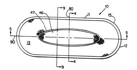
Figure 9 is a lateral cross-sectional view of the preferred :
sanitary napkin anbodiment shown in Figure 1 taken along section
line 9-9 of Figure 1 through the portion of the s-nitary napkin
which is dispos d beneath the c-nter of the vaglnal orifice when
the s nitary napkin is ~orn. `-
Figure 10 is a top plan view of the t~st apparatus plungers. `
Figure 11 is a ~iew of a cast moldea lateral cross-section of
the preferred sanitary napkin embodiment shown in Figure 1 when
the sanitary napkin is being worn the cross-section being taken
along the lateral centerline of the sanitary napkin~
2S Figure 12 is a top plan view of the preferred deformation
elem nt embodiment shown in Figure 6 when the preferred
sanit ry napkin embodiment shown in Figure 1 is being worn by a
female who is naked and in the standing position with the
sanibry napkin bdng subjected to lateral compresslve forces by
the wearer's thlghs.
7 - ~ 324460
Figure 13 is a side view of the preferred deformation elernent
embodiment shown in Figure 12
Figure 14 is a lateral cross-sectional view of an alternatively
preferred deformation element cmbodiment of an alternatively
S preferred sanitary napkin embodiment of the present invention
which is being worn. the cross-section being taken through that
portion of the sanitary napkin which is disposed beneath the
center of the vaginal orifice when the sanitary napkin is worn.
Figure 15 is a 1ateral cross-sectional view of a deformation
element of a sanitary napkin which is being worn the sanitary
napkin not being within the scope of the p-esent invention.
F~gure 16 is a lateral cross-sectional view of the preferred
deformation element embodiment shown In Figure 12 taken along
section linc t6-t6 of Figure 12 through the portion of the
deformation element which is disposed beneath the center of the
vag~nal orifice when the preferred sanit~ry napkin embodiment of
the present invention shown in Figure 1 is worn.
.
Figure 1~ is a lateral cross-sectional view of the preferred
d~formation el-m nt embodiment shown in Figure 12 taken along
sectbn line 17-1~ of Figure 12.
Figure 1~ is a bteral cross-sectlonal view of the preferred
d fo~tion el ment ombtment shown in Figure 12 taken along
s~ction line 1~ of Figure 12.
Flgure 19 is a l~teral cross-sectlonal vlew of the preferred
2S deformathn element embodiment shown in Figurc 12 taken along
section line 19-19 of Figure 12
Figure 20 is a depktion of the lateral cross-sectional view of
the preferred deformation element embodiment shown in Figure t6
depkting the deformatlon of the deformation element when the
body surface of the preferred sanltary napkin embodiment of
Flgure 1 makes intimate contact with the pudendal region of a
we~r~r.
8 ~ 324460
~igure 21 is a top plan view of an alternatively preferred
sanitary napkin embodiment of the present invcntion having
portions cut away to reveal under~ying structure and with the
portion of the sanitary napkin which contacts the wearer facing
the viewer~
Figure 22 is a lateral cross-sectional view of the alternatively
preferred sanitary napkin embodiment shown in Figure 21 taken
along section line 22-22 of Figure 21
Figure 23 is a lateral cross^sectional view of another
lo alternatively preferred deformation element embodlment of another
alte-natively preferred sanitary napkin embodiment of the present
invention taken through the portion of the deformation element
which is disposed beneath the cente- of the vaginal oriflce when
the sanitary napkin is worn.
.
Figure 24 is a top perspective view of another alternat~vely
preferred de-ormation element embodiment of another alternatively
preferred s nita-y napkin embodiment of the present inventton
Figure ~5 is a top plan view of another alternatlvely
pr~f rred defwmation element embodiment and sanitary napkin
embocilment of th~ present invention. the topsheet not being
si n. ~`
Figure 26 is a bottom plan view of another alternatively
preferred defo~tion element embodiment and sanitary napk~n
embodlment of ti~ p-esent invention
. . .
Figure 2~ is a top pe-spectlve view of the alternatively
pr ferred d formation element embodlment and sanitary napkin
embociiment sho~n In Figure 26 as it would appear when worn
DET~ILEO DESCRIPTION OF PREFERRED EMBODIMENTS
The present invention relates to disposable absorbent articles
such as sanit~ry napkins, and in particula- to sanitary napkins
having a tlexur~ristant deformatlon element having a convex
upward configured body facing surface when worn `
..
9 1 324460
As used hlerein, the term "disposable absorbent article"
refers to articles which absorb and contain body cxudatcs and
more specifically refers to articles which are placed against or in
proximity to the body of a wearer to absorb and contain the
various exudates which are discharged from the body (e g,
blood, menses, urine) and which are intended to be discarded
after a single use (i e, they are not intended to be launder~d or
othcrwise restored or reused ) A preferred embodiment of the
disposable absorbent article of the present invention is shown in
o Figures 1 thrDugh 5 as it would be used in a sanitary napkin 10
As used herein, the term "sanitary napkin" refers to an article
which is worn by females adjacent to the pudendal region and
which is intended to absorb and contain menstrual fiuids and
other ~agina~ discharges Interlabial devices which reside
partially within the wearer's vestibule are also within the scope of
this invention ~s used herein . the term "pudendal" refers to
the externally visible female genitalia and is limited to the labia
majora, the labh minora, the clitoris and the vestibule
~s can be s en in Figures 1 through 5, a preferred sanitary
napkin 10 basically comprises a deformation element 20 and an
absorb nt me ns 39 The absorbent means 39 may be any mcans
whkh Is gener~ compressible, conformable, non-irritating to the
wear r's skin ~nd capable of absorbing and containing liquids and
cert-in body exudates such as menses, blood and urlne If the
absorb nt m~ns 39 is comprised of more than one constituent
p rt or mat rbl, one part or material of the absorbent means 39
may not be absorbent or llquid permeable, so long as the
combination of parts or materlals has some degree of absorbency
and some degree of the properties set forth above the
absorbent means 39 has a first major surface 91 and a second
major surfxe 92 In the preferred embodiment illustrated, the
deformation element 20 serves as the liquid impermeable backing
for th- sanitary napkin 10 and has a body facing surface 16, a
bottom surf ce 1~, and a perlphery 33 which comprises the
3S element side edges ~3t and the element end edges 32 In the
pr-ferred embodiment shown in Figures 1 through 5, the
absorbent means 39 is superimposed on the deformation element 20
such that the second major surface 92 of the absorbent means 39
is adjxent to the body facing surface 16 of the deformation
~o 1 3244 60
element 20 Fwrther, in the preferred embodiment shown in
Figures 1 through 5, the absorbent means 39 comprises an
absorbent co-e 40 and a liquid permeable topsheet 45 The
absorbent core ~0 has a first major surface 43, a second major
surface 4~, core side edges 41 and core end edges 42 The
absorbent core 40 iS superimposed on the deformation element 20
such that the second major surface ~4 of the absorbent core 40 is
adjacent to the body facing surface 16 of the deformation element
20 The topsheet ~5 overlays the irst major surface 43 of the
absorbent core ~0
The sanitary napkin 10 h3s a liquid receiving body surfæe
13 which is generally defined by the topsheet 45 and a garment
surface 14 which is generally defined by the b~ttom surface 17 of
the deformathn element 20 Prefe-ably the topsheet 45 and the m~-
deformation element 20 have length and width dimensions generally
larger than the absorbent core ~0 so that they extend beyond the
core side edges 41 and the core end edges 42 of the abso-bent
core 40 where they are associated together in a suitable manner - `;
~s used hereln, the term "associated" encompasses configurations
whereby first member is directly joined to a second member and
configurations whereby a first member is indirectly joined to a
s conFi member by affixing the first member to intermediate
m mb rs whkh in turn are affixed to the second member The
extension of the topshcet ~S and/or the deformatlon element 20
2S b yond the eore sid~e edges ~1 and the co-- end edges 42 of the ~`
absorb nt eor ~0 forms the longitudinal side edges 11 and the
nd edg s 12. ~spectively, of the s-nitary napkin 10 The
longitudinal s;de edges 11 and the end edges 12 of the sanitary
napkin 10 eompri# the periphery lS of the sanitary napkin 10
Looklng at some of the members of the S?nitary napkin 10
more specifieally, the topsheet 45 is positToned adjacent the first
major surf ee ~3 of the absorbent core 40 and ovcrlays a major
portion of the absorbent core 40 so that when exudates are
discharged onto th- topsheet 45 they will transfer ~rom the
3S ~ body surfaee 13 of the topsheet 45 through to the absorbent core
~0 where they are absorbed by the absorbent core 40 The
topsh~t IIS extends outwardly toward the edges of the absorbent
core 40 so that a major portion of the absorbent core 40 îs
.'`'
11 ~ 324460
disposed bet~een the topsheet ~S and the deformation element 20
In the pre~e-red embodiment shown in Figures 1 through S, the
topsheet ~S has length and width dimensions generally larger than
those of the absorbent core 40.
The topsheet ~S is compliant, soft feeling, and non-irritating
to the wearer's skin Further, the topsheet 45 is liquid
pen~ious, permitting liquids to readily transfer through its
thickness A suitable topsheet 45 may be manufactured fron~ a
wide range of materials such as formed thermoplastk films.
o apertured plastic films, porous foams, reticulated foams, natural
fibers (e g, wood or cotton fibers), synthetic flbers (e g,
polyester or polypropylene $ibers) or from a combiration of
natural and synthetic fibers, with formed films being preferred
~ormed films are preferred for the topsheet ~S because they are
per~ious to liquids and yet non-absorbent Thus, the surhce of
the formed film, which is in contact with the body, remains dry,
thereby reducing body soiling and creating a more comfortable
hel for the wearer Suitable formed films are described in U S
Patent No 3,929.135. entit1ed "Absorptive Structure Ha~ing
tapered C~pilbries~, which patent issued to Thompson on
December 30, 1~5, U.S~ Patent No. 4,32~1,246, entitled
~Disposable ~bsorbent ~rtkle Having ~ Stain Resistant
Topsheet~, ~hich patent issued to Mullane and 5mith on ~pril t3,
19~2, U.S. P~tent No ~,3~2,31~, entitleai "Resilient Plastk Web
2S Exhibiting Fiber-Like Properties", which patent issu d to Radel
and Thompson on ~ugust 3, t982, and U . S Patent No
63,0~5, entitled "Macroscopically Expanded Three-Dimcnsional
Pl stlc Web Exhibiting Non-Glossy ~isible Surface and Cloth-Like
T ctile Impresshnn, which patent issued to ~hr, Louis, Mullane,
and Ou llete on July 31, 1984.
,
In a preferred embodiment of the present invention, the
body surf ce 13 of the topsheet ~5 is hydrophilic The
hyd-ophilic body surface 13 helps liquid to transfer through the
topsheet 45 faste- than if the body surface 13 was not
3S hydrophilic. l'his diminishes the likelihood that menstrual fluid
will flo~r off the topsheet 45 rather than being absorbèd by the
A absorbent core ~10~ In a preferred embodiment, the body surface
. '. ~'`':-
12 t 324460
~ 3 of the topsheet 45 is made hydrophilic by treating the body
surface 13 with a surfactant It is prefêrred that the surfactant
be substantially evenly and completely distributed throughout the
body surface 13 of the topsheet 45 This can be accomplished by
any of the-common techniques well known to those skilled in the
art For example, the surfactant can be applied to the topsheet
5 by spraying, by padding or by the use of transfer rolls
In addition, in a preferred embodiment~ as illustrated in
Figure t, the topsheet 45 may ad~antageously be provided with a
target æquisition 20ne ~6~ As shown in Figure 1, the 20ne 46
has larger openings and a greater percentage of open area than
the remaining regions of the topsheet 45 The 20ne 46 serves
two purposes First, the larger openings and greater open area
provide quicker acquisition of fluid gushes which are often
lS experienced when a woman rises from having been seated or
Iying, whereas blood and mens-s have accumulated in the vaginal
canal or vestibule~ Second, the larger openings of the 20ne ~6,
as compared to the est of the topsheet 45, p ovide more complete
acquisition of the sometimes highly viscous menses Without the
20ne 4C, less absorption of exudabs may take place and the
unabso-bed exudates m~y lay in contact with the body and cause
irritation or they may flow to the edges 11 and 12 of the sanitary
r, pkin 10 ~nd c-use soilins~ The 20ne~ ~6 can be positioned
any~h re on the topsheet 45 and can have any shape The 20ne
2S ~6 c n be as small s proper functioning will allow or almost as
brge as tl~e topsheet ~S, itself. However, because the larger
op nlngs of tl~ ~one ~6 may not ~revent rewet as well as the rest
of the topsh~t ~IS, the 20ne ~6 prefeeably has an area great
enough to be in contact with the menses as it exits the ~estibule
yet not so large as to contact surroundlng skin surfaces which
could be soiled or irritated by rewet Preferably, as shown in
Figure 1, the 20ne ~6 is posltioned on the topsheet 45 in an area
where menses wlll contact the 20ne ~6 fi-st before contacting the
est of the topsheet 45 This area Is preferably dlsposed beneath
3S the vestibule nd more preferably beneath the vaglnal oriflce In
the preferred cmbodlment of the topsheet ~5 shown in Figure 1,
the brget xquisition 20ne 46 is symmetrically located on the
topsheet ~S due to the fact that the preferred embodiment of the
napkin 10 shown is designed symmetrically so that the napkin 10
13 1 324460
and the target acquisition ~one ~6 will function properly, when
worn, no matter which direction the napkin tO is worn.
As seen in Figure 1, the perimeter of the target acquisition
20ne 46 is defined by an inner perimeter region 47. In the
preferred embodiment shown, the inner perimeter region 47 is
impervious. The inner perimeter region ~ may be formed by
thermomolding a polymeric topsheet 45 to a polymeric f;ber
absorbent core ~0 or by gluing or fusing a topsheet ~5 to a fluff
pulp absorbent core 40. The inner perimeter region ~t is not
primarily in~ended for the function of defining the outer perimeter
of the 20ne ~6, but, instcad is intended to hold the topsheet q5
in contact with the absorbent core 40 so that the topsheat 45 will
not shift or roll, and also so that the absorb nt core ~0 will stay
in plxe and have better integrity. Further, the inner perimeter
lS region ~ may not be liquid impervious but will function equally
well if it is liquid pervious. In the preferred embodiment shown
in Figure 1, the configuration of the inner perimeter region ~7 is
made to correspond to the outline of the protuberance 71 of the
deformation element 20, which will be explained in more detail
later in this specification. ~he inner perimeter region 47 creates
a slight trough around the 20ne ~6 causing the 20ne 46 to havè a
somewhat pillowing effect~ In an alternative embodiment of the
napkin 10, th~ deformation element 20 has dimples In regions
which corr spond to the inncr perimeter region ~7 and which
2S extend through tt)e absorbent core ~10, tn whleh case the topsheet
~5 is th rmomold~d or glued directly to the dimples.
The absorbent core ~0 may be any means which is generally
compressible, conformable, non-irritating to the wearer's skin,
and capable of absorbing and containlng liquids and certain body
exudates. T~ absorbent core 40 may be manufactured in a wide
varhty of si2es and shapes te.9., rectangular, hourglass, etc. )
and from a wide variety of liquid absorbent materlals commonly
us d in dlsposable sanitary napkins, dlapers and other absorbent
artkles, such as comminuted wood pulp whkh is generally
3S referred to as airfelt and which is preferred. Examples of other
.
suitable absorbent materials include creped cellulose wadding,
absorbent foams, absorbent sponges, super absorbent polymers,
absorbent hydrogel materials, polymeric fibers, or any equivalent
~ . ''
1 324460
14
materials or canbinations of materials. The total absorbent
capacity of the absorbent core ~0 should, however, be compatible
with the design exudate loading for the intended use of the
absorbent article. Further, the si2e and absorbent capacity of
the absorbent core qO may be varied to accommodate wearer's
ranging in siie and also ranging in the expected amount of
exudate fluid volume~ For instance, a different absorbent capacity
may be utili2ed for sanitary napkins intended for daytime use as
compared with those intended for nighttime use or for sanitary
napkins intended for use by teenage females as compared with
those intended for use by more mature women.
~ pre~erred embodiment of the sanitary napkin 10 has a
generally rectangular shaped absorbent core qO having rounded
end edges ~2 and is intended to be worn by generally all females.
The absorbent core 40 is preferably a batt of airfelt having a
laminate of hydrogel forming material 3~ adjacent to and
underlaying ~he airfelt fibers. Suitable hydrogel forming
materials are disclosed in` U.S. Patent 4,65q,039, entitled
~Hydrogel-Forming Polymer Compositions For Use In ~bsorbent
Structures", whieh patent issuest to Brandt, Goldman and Inglin
on March 3t, 193~ Preferably, the batt of airfelt is about 6.0
centime~rs wide tlateral dimension) and about 19.0 centimeters
long (longitudin~t dimension)~ The absorbent core ~0 has a
generally uniform c-lip-r of at~out q~6 millimeters, an absorbent
2S cap~city of f~ about ~.0 grams to about 10.0 grams of water
per gram of absorbent materbl ~nd a density of about 0.1 grams
per cu~k c~nthlet~r~ It should be understood, however, that
the si2e. sh pe, confisuration, and total absorbent capacity of
the absorb~nt core ~0 may be varied to accommodate wearer's
ranging in si2e and expected fluid fiow. Therefore, the
dimensions, shape. anq connguration of the absorbent core ~0
may be varied (e.g., the absorbent core may have a varying
callper or a hydrophllk gradient).
The deformatlon element 20 is flexure-resistant. As used
3S herein, the term ~tlexure-resistant" refers to an element which
will support a bending moment, in contrast to an element which
will support only axial ~orces. lhe deformation element 20 of the
present invention has a preference for having a convex upward
.. .
15 1 324460
configuration when the napkin 10 is subjectcd to lateral
compressive forces t 00, ~hen worn . Prefe-ably, the deformation
element 20 of the present in~ention will have a convex upward
configuration when the sanitary napkin 10 is worn by different
S females wearing the same designed napkin 10 for a period of
fifteen minutes in at least seventy of one-hundred trials. In
some configurations of the element 20, the wearer may have to
initially manipulate the element 20 into a convex upward
configuration either prior to or just after plxement of the napkin
10 to the wearer's body~ Preferably, the deformatlon element 20
is manufætured from a moldable substance. More prehra~ly the `-
element 20 is manufactured from a thermomoldable substance, and
most preferably a radiation cross-linked polyethylene foam. Such
a foam is manufxtured by Voltek. Inc~ of ~awrence,
IS Massachusetts, and marketed in the trade as ~oltek Volara~ Type . .
2~. ~nother suitable foam is a thermomoldable cross-linked
closed cell polyolefin which is manufactured by Dynamit Nobel of
~merica, Inc~ of South Holland, Illinois, and marketed in the
tr de as Dynamit Nobel Troc~llQn' q~ypQ X~1400. A preferred
deformation element 20 has a caliper of from about 1~25 to about
2.5 millimcters and more preferably from about t~?5 to about 2.0
millimeters. ~ prefcrred element 20 is formed from a polyethylene
fo m sh~t w~ich is subse~uently subjected to molding by a
kno~n th rmomolding process. The sheet is subjected to
2S thermomolding t a temperature of from about 1 t 0C to about
20SC to form the element 20. Other suttable foams are made
rom sueh subst~nces as polyethylene, polypropylene, polyester,
polybutylen~, ethylene vinyl aeetate, polyurethane,
th rmobondable cellulose, latex, silicone elastomerics and others.
Ho~re~er, the element 20 need not be made of foam. ~;
~Iternatively, the element 20 could be made of fibers, films or
sh~ts of cellulose, rayon, nylon, polyester, stiffened cotton,
polyethylene, vinyl aeetate, latex, rubber, plastic, heavy-weight
paper sueh as cardboard, coated paper, or a combinatton or
3S bminate of these or other materials. further, if the element
20 is suseeptible to being wetted when worn, then the element 20 -
must be moisture stable. In other words, elements which are
suseeptlble to wetting when worn and are not moisture stable, but
inste d are moisture unstable, are not within the scope of the
S0 present invention. As used herein, thè term "moisture unstable"
A :
16 1 324460
refers to materials which are held together solely by hydrogen
bonds andlor fibrous structures comprised of short fibers having
a length of 10 0 millimeters or less which are held together by
mechankal entanglement and frictional forces An example of a
material which is held together solely be hydrogen bonds is
sbndard toilet tissue which is a slu-ry of wood pulp laid on a
screen and subjected to drying ~n example of a material which
is held together by mechanical entanglement and frictional forces
is short-fiber fluff pulp which is air-laid and then compressed or
densified to promote interfiber entanglement Converxly if a
material is bonded at least partially through means other than
hydrogen or short-fiber mechanical entanglement and frictional
forces, then the material is moisture stable~ Examples include
short wood pulp fibers which are adhesively held together, foams
lS having chemical bonds other than just hydrogen, long synthetic
fibers suitably blended with short-fiber wood pulp and others
The reason that the element 20 must be moisture stable is that in
order for the element 20 to pro~ride continuing benefit when worn
and soiled, the element 20 should maintain a functional degree of
flexure-reslstance throughout a normal wearing time While It is
true that many moisture unstable elements form up nicely into a
convex up~ rd configuration and have flexural-resistance prior to
or shortl~ ~fter bdng worn, wh-n these el~nts are subjected to
perspi-atlon. ~te-. mens s or urine in the presence of wearing
nexures. th ir hydrog n or mechanical frictional bonds deteriorate
and the d~nt loses a large part, if not all, of its
xure-resistanc~ and. therefore, its usefulness~
Of course, a number of ingenious embodiments of the present
inventlon exist in ~hich the deformatlon element 20 does not
consist solely of a single homogenous material For example, the
element 20 may be comprised of fluff pulp having unbonded
regions and select d adhesively bonded regions which impart to
the element 20 a flexure-reslstance ~Iternatlvely, the element 20
may be comprls d of fluff pulp having thin strips or a lattice of
3S foam materlal dlsp rsed throughout the fiuff pulp to provide
flexur~resist nce ~Iso, for example, the element 20 may be a
polym-rk sheet having a stiffening grid bonded to it to provide
flexure-r sist nce In such cases where the element ~0 is a
combination of materials, if it is necessary to test the
, `
17 . 1 324460
flexure-resistance of the element 20 by the Circular 8end
Procedure, as explained below, then each constituent part should
be tested individually, if feasible, and also the combination of
materials should be tested as a ~hole.
Preferably, the elèment 20 has a flexure-resistance measured
by peak bending stiffness of at least about 100. 0 grams. More
preferably, the deformation element 20 has a peak bend;ng
stiffness of greater than about 200.0 grams, and most preferably
greater than about 350.0 grams. Depending on the element~s 20
design, peak bending stiffnesses of greater than 500. 0 grams
have been found aeceptable. As an element increases in
flexure-resistance, it generally mainbins its shape better, but it
also generally becomes more uncomfortable and increases wearing
awareness.
Peak bending stiffness is determined by a test which is
modeled after the .~STM D q032-S2 CIRCUL~R BEND PROCEDURE,
the procedure being considerably modified and performed as
follows. The cireular bend procedure is a simultaneous
multi-directional deformation of a material in which one face of a
specimen beean~s eoncave and the other face becomes convèx.
The circubr b nd procedure gives a force value related to
flexu-e-resist nce. slmultaneously averagtng stiffness in all
dir~ctions~ `
~PP~R~TUS:
2S The apparatus n~cessary for the CIRCUL~R BEND
PROCEDURE is a modi~ied Clrcular Bend Stiffness
Tester, having the following parts:
T~o smooth-pollshed steel plate platforms which
are 102.0 x t02.0 x 6.3S mlllimeters, one having
an 1~. ~5 millimeter diameter orifice and the other
having a 31.~5 millimeter dlameter orifice. The lap
edge of e~ch orifice should be at a ~5 degree angle
to a depth of ~.75 millimeters.
1 3 2 4 4 6 0
~ plunger having an overall length of ~2 2
millirneters, a diameter of 6 25 millimeters, a bal~
nose having a radius of 2 97 millimeters and a
needle-point extending 0 88 millimeter therefrom
having a 0~33 mil!imeter base diameter and a point
having a radius of less than ~ 5 millimeter, the
plunger being mounted concentric with the orifice
and ha~ing equal clcarance on all sides Note that
the necdle-point is merely to prevent lateral
movement of the test speeimen during te5ting
rherefore, if the needle-point signiflcantly
adversely affects the test specimen (for ex~mple,
punctures an inflatable structure), then the
needle-point should not be used. The bottom of
the plunger should be set well above the top of
the orifice plate From thls position, the
down~ard stroke of the ball nose is to the exact
bottom of the plate orifice
~ force-measurement gauge, and more specifically
an Instron inve-ted compression load cdl rhe
load eell has a load range from about 0~0 to about
2000.0 grams~
~n aetuator. and more sp eifically the InstronlY
blodd No, 1122 ~ving an inverted compression
2S load e ll. ~he Instron t122 is made by the
Instron Engineering Co-po-ation, Canton,
Mas~chusetts.
NUMBER ~ND PREP~R~TION OF SPECIMENS
'.: . :`
In order to perform the predure for this test, as
expbined bdo~, five representatlve absorbent articles
are n~cessary, From each absorbent article, the
elem nt to be test d~ is removed In articles where the
deform-tion I ment 20 ts a combination of materials, as
earlie- explained, each constituent part should be
` test d separately, if feasible, and also, the element
A should be tested as a whole~ From one of the five
: `
19 1 324460
elements to be tested, some number Ny~ of 37,5 x 3~.5
millimeter test specimens are cut. If any portion of the
element mee~s the parameters of this tcst, then the
element as a whole satisfies the test. Therefore, a
S number lly" of different specimens should be tested
from each element. Cèrtainly. the structurally most
rigid portion of the element should be tested.
Preferably, a test specimen is cut from a portion of the
element which has a convex upv~ard configuration, as
later described. ~here may be portions of thc elements
which are not 37.5 x 3t.S millimeters. In such a case,
the largest a~ailable specimen of the element should be
tested. The test specimens should not be l'olded or
bent by the test person and the handling of specimens
must be kept to a minimum and to thê edges to avoid
affecting flexural-resistance properties. i~rom the four
remaining elem~ents, an equal number ~Y" of 37~5 x 17,5
millimeter specimens identical to the specimens cut ~rom
the first element are cut. Thus, the test person
should ha~e ~Y" number of sets of five identical
specimens.
PROCEDURE
The procedu~e for the CIRCUL~R BEND PROCEDURE is
s follo~s. The specimens are conditloned by leavlng
2S th~m in a room whkh Is 21 ~ 1C and 50 ~ 2~ relative
humidity for a p~riod of t~o hours. It has been
recogni2 d th~t specimens ha~ing an uncompressed
optkal caliper of 6.35 millimeters or greater tend to
bunch up in the 18. 75 millimeter test plate orifice and
thereby give readings ~hich are more related to the
speclmen's compressbn reslstance rather than the
sp cimen's flexure-resistance. Thus, specimens having
an uncompressed optical caliper of 6.35 milllmeters or
greater should be testcd using the test plate having the
3S orifice of 31. ~5 millim~ters. Whichever plate is used,
the test procedure and calculations remain the same and
the preferred flexure-resistances previously given also
remain the same. The tester plate is leveled. The
. ~ ~
1 3244~Q
plunger spced is set at 50 0 centimeters per minute per
full stroke length A sixcimen is centered on the
orifice platform below ~he plunger such that the body
facing surface ~6 of the specimen is facing the plunger
and the bottom surface 1~ of the specimen is facing the
platform The indicator 2ero is checked and adjusted,
if necessary The plunger is actuated Touching the
specimen during the testing should be avoided The
maximum force reading to the nearest gram is recorded
The above steps are repeated until all fiv~ of the
specimens have been tested
CALCULATlOiN
The peak bending stiffness for each specimen is the
maximum force reading for that sp¢cimen~ Remember
that ~Y" number of sets of five identical specimens were
cut Each set of five identical specimens are tested
and the five values received are averaged Thus, the
test person now has an average value for each ôf the
"Y~ sets tested Remember, if any portion of the
elem~nt satisfies this test. then the elem¢nt as a whole
s tisfies th test Therefore the flexure-r¢sistance for
a partkubrly designed element is the great¢st of these
averago i~k bondlng stiffnesses
:
In the prof rr d embodiment of the sanitary napkin 10 shown
in Figures t th~ough 5 the deformatbn element 20 is positioned
such that the body faclng surfxe 16 of the deformation element ~ ` `
20 Is adjacent to the second major surface 4~ of the absorbent
core ~10 In the preferr¢d embodtment, the deformatton element 20
Ts substanUally liquld impermeable and ser~es as the liquid
imp rm~able b cking of the sanita-y napkin 10 The deformation
i~nt 20 undorlays a maJor portlon of the absorbent core 40 so
that ¢xudates whlch are absorbed by and contained within the
absorb nt core ~10 are pre~ented from soiling adjacent garments
and llnens In the preforred embodiment, the deformation element
20 has bngth and width dimensions generally larger than the
absorbent core ~10 so that tho deformation element 20 extends
beyond the core side edges 41 and the core end edges 42 to the
. ' . . .
:-` ' 132~4bO
longitudinal side edges tl and the end edges ~2, respectivoly, of
the sanitary napkin 10 where it is associated with the topsheet
45 In a pre~erred embodiment, the topsheet ~5 and the
deformation element 20 are heat-sealed to each other near and
along the periphery 15 of the sanitary napkin 10
In a preferred embodiment the foam element 20 has a
closed-cell construction on its body facing surface 16 so that it is
non-absorbent, However, the foam element 20 may be of an
open-cell construction on its body facing surface 16 so that it is
o absorbent Ho~rever, when the foam element 20 is used as the
liquid impermeable backing of the sanitary napkin 10, the element
20 should be substantially liquid impermeable~
A preferred deformation element 20 of the sanita-y napkin 10
shown in Figures t through S is shown in Figures 6 through 8
In the preferred embodiment, the element 20 has a length of
about 20 5 centimeters, a width of about 3 0 centimeters and a
generally uniform caliper of about 2 0 millimeters, except for the
flexure hinges 23~, 23B and 23C which have a caliper of about
1 25 millimeters In a preferred embodiment, the deformation
el_nt 20 h s flexure means 23 for inducing the deformation
el~nt 20 to ~nd in preconceived way into a preconceived
geometric con iguratlon when the sanitary napkin 10 is subjteci
to bteral compr ssive forces 100 when worn There are a number
of possible ~-xure means 23 ~ preferred fiexure means 23 are
2S t~ flexure hinges 23~, 23B and 23C shown in Figures 6 through
3 ~ nexure hinge initiates deformational development of
pronceh~ed geometric configurations /~ flexure hinge creates
different bend-resisbnces xross the width of the deformation
den#nt 20 The difference in bend-resistance can be crated by
g ometric disconUnuities in the element 20 as by pre-set folds,
scorlng, indent thns, perforations, or fairly abrupt changes in
elevation The dlfference can also be created by changes tn
bend-resistance cross the width of the element 20 due to changes
in materbl propertles of the element 20 as by locali2ed compaction
3S or by tho combination of different materials across the wldth of
the element 20, wherein the materials have different
flexure-resistances In a preferred embodiment, the fiexure
hinges 23~, 23B and 23C induce the deformation element to have
. . .
~324460
a convex upward configuration when the napkin tO is worn ~he
convex upward configuration of the element 20 causes the
absorbent core ~0 and the topsheet 45 to also have a convex
upward configuration, and conse~uently, the body surface 13 of
the napkin 10 has a convex upward configuration when the napkin
~0 is worn
The preferred embodiment of the element 20 shown in
Figures 6 through 8 has a linear central hinge 23A, a pair of
curvilinear thigh hinges 23B, and a pair of curvilinear
lo protuberance hinges 23C, all of which are of the geometric
discontinuous type and all of which have been thermomolded into
the element 20 From each element side edge 31, the element 20
slopes inwards and downwards to form walls 2~ having bases 74
which are adjxent to the curvilinear thigh hinges 238 7'he
lS walls 72 comprise that portion of the element 20 bet~een the thigh
hinges 23B and the element side edges 31 l'he walls 72 have a
pudendal facir~ su-fxe 73 Figures 6 and 7 illustrate that the
thigh hing-s 23B extend generally longitudinally and curve inward
from the element side edges 31 so as to approximate the curvature
~o of a weare-'s thighs In other words the thigh hinges 23B are
arcuate ~herein the midpoint of the arc is the greatest disbnce
from the element side edges 3~ rhe thlgh hinges 23B have a
g nerally ~U~ shaped cross-section as shown in Figure
~djacent to the longitudinal midpoint of the thigh hinges 23B are
the curvillne r protuberance hinges 23C which serve to define the
perim t r of th~ protub~rance 7t of the element 20 as shown in
Fbur s 6 and ~ The protuberanee hinges 23C are arcuate
wherein the midpoint of the arc is the greatest distance from the
longitudlnal xis 90 ~he protuberance hinges 23C are formed
into the elem nt 20 as a result of the thermomolding formation of
the protuber nce 71, ~hus, as shown in FTgure 8, the
protuberance hinges 23C are the result of a fairly abrupt change
in elevatlon ~cross the element 20 ~s shown tn Figure 8, from
the protuberance hinges 23C the element 20 curvilinearly slopes
3S upward to the llnear central hinge 23~, thus forming a
protuberance ~t The protuberance 71 is provided to promote
and initiate some of the desired bending deformations of the
element 20 and, in particular, the protuberance 71 predisposes
the element 20 to bend in such a way that the body facing
23 ~ 324460
surface 16 of the element 20 will have a convex upward
configuration when the napkin 10 is subjected to iateral
compressive forces 100 when worn, as will be later cxplained. Of
course, the protuberance ~1 need not be provided and, in fact,
the element 20 can be planar or downwardly cup shaped.
However, such configurations might require a more complex
design that might require more compressive force and more
mechanical action in order to create a convex upward
configuration. ~hus. by providing the element 20 with a
protuberance ~1 and thereby giving the body hcing surface 16 of
the element 20. and more particularly that portion of the body
facing surface 16 which is superimposed over the protuberance
71, a pre-formed convex upward configuration, the element 20
need only maintain a convex upward configuration when the
napkin 10 is subjected to lateral comp-essive forces tO0, when
worn, in contrast to an element 20 that is planar or downwardly
cupped shaped when applled but assumes a convex upward
configuration when worn. ~s used herein, the ~erm "maintain"
includes embodiments wherein the body facing surface 16 of the
~o element 20 retains the same convex upwaed configuration that it
had p ior to the application of lateral compeessive forces tO0 when
worn and embodiments wherein the body facing surface` 16
assumes a different convex upward configuration than it had prior
to the application of bteral compressive forces 100 when worn.
In add;tion. recogni2ing that an object of the present invention is
to put the bady surf ce 13 of the napkin tO in intlmate contact
with the external surfaces of the labia majora when worn, the
protub-- nce ~1 gives the element 20 and, consequently the
napkin ~ 0, some pre-formed elevation to aid in providing such
intimate contaet. ~s seen in Figures 6 and 7, the central hinge
23~ extends longitud;nally along the longitudinal axis 90 of the
element 20 nearly from one end edge 32 of thè element 20 to the
othe- end edge 32. ~s shown in Figure 8, the central hinge 23A
has a generally inverted "U" shaped cross-section.
:- ' ', '
~he previous description of the sanitary napkin 10, and
particularly the deformation element 20, has been directed to the
element's 20 "-t rest" configuration. However, when the sanitary
napkin 10 is wo-n, at least a portion of the body facing surface
16 of the deformation element 20 must have a convex upward
2.; ~ 324460
configuration. ~s used herein, the term "convex upward
configurationU ;ncludes embodiments wherein at least a portion of
the body facing surface 16 of the deformation element 20 has a
convex shape.
.
~he presence of a nconvex upward configuration" is
determined as follows, the following explanation being given with
refercnce to Figures 9 through 11. First, two plungers 200
having a radius of about ~6 . 2 millimeters are positioned
symmetrically across from each other so that the midpoint of the
faces of the plungers 200 are about 25.~ milllmeters apart. The
curvature of the plungers 200 is intended to approximate the
cùrvature of the thighs of a representative number of women.
The 25. ~ millimeters distance is intended to approximate the
distance between the thighs of a representative number of women,
IS when standing. ~ top ~fie~ of two properly positioned plungers
200 is sho~n in Figure 10~ ~he plungers 200 have a face 205
height of about St~0 millimeters. a bottom lip 220 having a width
of about 5~0 millimeters and a thickness of about S.0 millimeters.
With the bociy surfxe 1~ of the napkin to be tested factng up
and the garment surface 14 of the napkin facing down, the
napkin is placed bet~een the plungers 200 in the shape that the
napkin 10 gene-ally has when worn~ ~he napkin may ha~e to be
manipulated into ;ts Hin use" shape. Qften, this "in use" shape
c-n be det~rmined through simple visual observations of females
2S ~earing the napkin. If thè shape is not determinable through
~isual observatiJon. at least one feasible alternati~e that is
avaibble i5 Magnetic Resonance Imaging (MRI). Magnetic
resonance Images of females wearing sanitary napkins which have
been saturated ~ith mineral oil have been used to give accurate
depictions of the shape a sanitary napkin has when worn. As
soon as the sanitary napkin is properly positloned between the
plungers 200, a c-st molding of the sanitary napkin is made~
The cast moldlng is lfior the purpose of permanently "free2ing" the
napkin in this "in use" eonfiguration so that the napkin can be
further studied. The cast mold can be made from a number of
different materials. Preferably, the material that is used will
penetrate into the absorbent means. ~wo materials that have
been found suitable are a hard-casting material which is marketed
as ~virol`~ 1 to 1 Polymer Coating by Environmental
A
.. ... . .. . ..
2s 1 324460
technology Inc of F;elds Landing, California and a soft-castinq
material which is a mixture of 46~ Veisamid" 125 resin which is
marketed by the Henkel Corporation of Minneapolis, Minnesota,
~1% EPON'Y 812 hardener which is marketed by Polaron Equipment
S Limited of Watford , Connecticut and 23~ 1, 1, 1 Trichloroethane
thinner ~he casting material can be poured directly into the
napkin if the "in use" configuration is susceptible to such (i,e,,
for example boat or cupped shaped) If not, a thin sheet of
aluminum fôil can be placed around and under the napkin so as to
create a receiver for the casting material The aluminum foil
receiver can then be filled so as to submerge the napkin in the
casting material Either way, the napkin should substantially
retain its in-use shape After the casting material has set, any
number of lateral cross-sections can be cut along the longitudinal
length of the napkin ~rom these lateral cross-sections, a person
can determine whether the napkin has a convex upward
configuration by performing the following test, reference being
directed to the cast molded lateral cross-section of the napkin 10
shown in Figure tl While looking directly at a cross-section, if
there is a point on the body facing surface 16 of the element 20
that has an elevaUon of at least about 2 S millimeters above either
outer perimeter of the body facing surfxe 16, then the body
fxing surfaee t 6 of the element 20 has a convex upward
eonfiguration If there is such a point, the point is preferably
at le st about S 0 millimeters above either outer perimeter of the
body f chg surface 16 If there is no such polnt, as per the
bteral cross-secthn shown in Figure 11, then, starting from the
left outer perimet r of the body facing surface 16 of the element
20 ~nd moving to the right, the body facing surface 16 is
scanned until an inflection point S0 between a do~vnward slope and
an upward slope is found If there is a first point 51 along the
body facing surface 16 to the right of the inflect~on point 50
which has an elevation of at least about 2 5 milllmeters above the
inflectlon point 50, and a second point 52 along the body facing
3S surface lC to the right of the first point 51 which has an
elevation below the fl-st point 51 of at least about 2 5 millimeters,
as per the lateral cross-section shown in Figure 11, then the
body hcing surface 16 of the deformation element 20 has a convex
upward conflguration Preferably, the first point 51 has an
elevation of at least about 5 0 millimeters above the inflection
A
.
- 26 1 3-24~60
point 50 and the second point 52 has an elevation of at least
about 5 0 millimeters below the first point 5? ~he body facing
surface 16 must have at least one convex upward configuration
but can have more Preferably a portion of the body facing
S surface 16 of the element 20 in the central region 62 of the
element 20 will have a convex upward configùration~ More
preferably the portion of the body facing surface 16 of the
element 20 which is disposed beneath the center of the vaginal
orifice when the napkin 10 is worn will have a convex upward
configu~ation~ ~ cross-section of an alte-natively preferred
deformation element 20 embodiment of the present invention having
a body facing surfxe 16 having a convex upward conflguration is
shown in Figure 111 An example of a deformation element 20 not
within the scope of the present invention having a body facing
lS surface 16 but not havins a convex upward configuration is
shown in ~igure 1S
Heretofore the sanitary napkin 10 and particularly the
deformathn element 20 have basically been described in their "at
rest" ti~e . not worn) configurations However because the
general population of women have thighs which are too close
together not to apply any laterally compressive forces 100 to the
napkin 10 wl~n worn the Hat rest" configurations of the napkin
~0 and the el ment 20 will seldom if e~r be reali2ed when the
napkin 10 of the present in~ention is being worn Therefore the
fdlowing is d~c-iption of the dlffer nt anatomy conforming
5hapeS t~ deformation element 20 assum~s along the element's 20
I ngth wh~n the s~nltary napkin 10 is being worn and thereby
subjected to the bteral compressive forces 100 o~ the wearer's
thighs~ In the preferred embodiment of the sanitary napkin 10
illustrated in Figures 1 through 13 and 16 through 20 the
~bsorb~nt me ns 3~ whkh is associated with the element 20
gen~rally nexes in cooperatlon with the element 20 More
specifically. the topsheet ~S which is affixed directly to the
elem nt 20 in the periphery 15 of the napkin lQ and the
3S absorb nt core 40 ~hich is disposed between the topsheet 45 and
the element 20 generally flex in cooperatton with the element 20
thus in the preferred embodiment the cross-sectional
confgurations of the napkin 10 along the napkln's 10 longitudinal
length and specifically of the absorbent means 39 which in the
27 1 324460
preferred embodiment comprises the topsheet 45 and the absorbent
core ~0 generally mimic the cross-sectional con~igurations of the
elernent 20 In other embodiments the cross-sectional
configurations of the napkin 10 and the absorbent means 39 may
not mimic the cross-sectional con-igurations of the elem~ent 20
As seen in Figure 12 when a preferred embodiment of the
sanitary napkin tO i5 subjected to lateral compressive forces 100
as when worn the element 20 assumes a generally hourglass
shaped top plan viêw~ ~he portion of the element 20 which lies
~eneath the pudendum of the wearer between the anterior
commissure and the posterior commissure. when worn is the
central region 62~ rherefore when the preferred napkin 10
embodiment of the present invention is wo-n the central region
62 of the element 20 shown in Figure t2 extends from about the
lS line 81 whieh is disposed beneath the wearer's anterior
commissure to about the line 82 which is disposed beneath the
wearer's posterhr commissure~ The distance between the lines 8t
and 82 or their relative position on the napkin 10 can vary
depending upon the Si2e of the wearer and the positioning of the
napkin 10~ l^he portion of the element 20 extending forward from
about th~ line 81 to t~le front end edge 32 is the front region 6t~
The portion o~ the element 20 extending backward from about the
line 32 to the back end edge 32 is the back region 63. Note that
wh n und~rp~nts are worn the f ont region 61 and the back
reglon 63 sho~m in Figure 13 may be forced to curve upwards
~not shown).
When the preferred embodiment of the napktn 10 shown in
Flgures 1 through S. is subjected to lakral compresstve forces
100 when ~orn. the central region 62 of the element 20 can
assume a number of dlfferent cross-sectlons ranging from its
at-rest conflgur-tlon shown by cross-sectlon in Figure 9 to the
in-use configurathn` shown by cross-section in Figure 16 As
seen in Figure 16. when the preferred sanitary napkin 10 is
subj cted to lateral compressive forces 100 when worn the
element 20 assumes a generally "W" shaped cross-section in the
central reglon 62 ~s seen in Figure 16 the walls 72 have
assumed a substantially vertical position the element side edges
31 rema~n adjacent to the walls 72 but are now displaced to a
: . . .
28 ~ $460
position abo~e the walls ~2 and into the uppermost part of the
wearer's legs at the crotch where there is minimum mo~ement and
the least cause for irritation. The bases ~4 of the walls ~2 are
adjacent to the thigh hinges 23B. The thigh hinges 238 are
providea to allow the walls ?2 to bend about the thigh hinges
23B, thereby assuming a subsbntially ~ertical position. Valleys
6~ are formed above and around where the bases ~4 of the walls
~2 meet the thigh hinges 238. rhe ~alleys 6~ are particularly
useful in diffusing exudates lengthwise to better util;2e the total
absorbent capacity of the napkin 10. From the thigh hinges 23B
to the protub~rance hinges 23C the element 20 slopes inwards and
downwards. Between the protuberance hinges 23C, the body
facing surface 16 of the element 20 has a convex upward
configuration. and more particularly a generally in~erted "U"
shaped configurathn. In addition, in the preferred embodiment
shown in Figure 16, the element 20, and particularly the
protuberance t1 has a generally inverted NU" shaped
cross-section~ In the preferred embodiment, the convex upward
configuration is generally symmetrically located between the
longitudin~l side edges 11, which in this embodiment are
synonymous with the element side edges 31. The linear central
hinge 23~ is generally symmetr;cally located between the
protuberance hinges 23C, along the longitudinal centerline 90 and
along the apex of the convex upward configuration.
B~fore t~ body f~cing surface 16 of the element 20 can
de~orm into the shape depicted in Flgure 16, the element's 20
ùp~ard movem nt may be impeded if the body surface 13 of the
napkln 10 makes inUmate contact with the wcarer's pudenda,
region, and more specifically the external surfaces of the labia
majora. If such occurs, the element 20, and speclfically in a
preferred embodiment the protuberance 71, will deform, and more
particularly in a preferred embodlment, spread or bu,ge
outwards. ~ comparison of Figures 16 and 20 illustrates how in a
preferred embodiment the protuberance ~1 deforms when the
protuberance's 7t upward movement is restricted by the external
surf~ces of the pudendal region.
. .. .
Ref rring again to Figure 12, it ts seen that the major
portion of the front region 61 is generally circular when ~iewed
' ~: "
~ 1 3244~0
from above the body faclng surface 16. The front region 61
remains generally circular because it is located beyond the thighs
and is, therefore, not directly affected by the lateral cornprcssive
forces 100 which are exerted by the wearer's thighs. However,
the region 6I is indirectly affected by the compressive forces 100
of the wearer's thighs and, in consequence thereof, assumes some
anatomy conforming shapes. Generally, the front region 6t of the
element 20 has an upwards opening cup shape when the napkin 10
is worn, This shape is depicted by cross-stion in Figure 17.
The curved end edge 32 in the front region 61 along with the
~exure hinges 23A. 23B, and ~3C facilitate the formation of this
cup shape.
' - ':
In thc preferred embodimeni shown. the back region 63. Iike
the front region 61. also assumes some anatomy conforming
l~ cross-sections when the napkin 10 is worn. However, in order to
adapt to the dif~erent shaixs of the anatomy in the buttocks
region of the wearer. the cross-sections are very different from
those in the front region C1~ In a preferred embodlment, as
shown in Figures 18 and 19. the back region 63 is configured to
fit the gluteal groove of a we rer when the napkin 10 is worn.
In the back reghn 63. the ~ody facing surface 16 Of the element
20 has a convex upward confguration. In the preferred
embodiment, t~ back region C3 of the element 20 has a convex
up~rd cross-s ction. The cross-section of the back region 63
best d pkting this sh pe is shown in Figure 18~ ~s seen in the
side vh~ of the element 20 shown in Figure 13 and in the
c~oss-sectlons sho~n in Figures 18 and 19, the central hinge 23A,
whkh Ts at the apex of the convex upward configuration in the
central region 62, remains at the apex of the convex upward
configuration into the back region 63. Since the napkin 10 will in
all probabillty be worn with an undergarment, such as panties,
the upward forces of the undergarment will preferably cause the
b~ck region 63 and the rearward part of the central region 62 to
curve upwards and follow the curve of the buttocks. The body
3S facing surface 16 of the element 20 in the back region 63 has a
ridge 70 which is configured to fit the gluteal groove of the
wearer, when worn. The ridge 70 is generally symmetrically
located between the longitudinal side edges 11 of the napkin 10
along the longitudinal centerline 90~ The ridge 70 fits the gluteal
:`~ " ' .
- 30 1 324460
groove of the buttocks to provide stability a~ainst sideward
shifting of the napkin lo Because the depth of the gluteal
groove varies as it moves fro~n the anus towards the wearer's
back, the back region 63 of the element 20 is designed so that it
flattens out somewhat and the ridge 70 becomes less pronoun~ced
as the ridge ~0 nears the end edge 12 of the back region 63
This change in formation is e~idence by a comparison of Figure
18, which is a cross-section through the back region 63, with
Figure 19, which is also a cross-section through the back region
o 63 but which is located more towards the end edge 12 of the back
region 63~ ` -
Basically, without intending to limit the scope of the sanitary
napkin 10 and particularly the deformation element 20 of the
present invention as shown in Figures 1 through 11 and 16
throùgh 20, the present in~ention is intended to function and
provide the benefits as follows~ The following is a description of
only one means of progressi~e deformation of the napkin 10 and it
should be recQgni2ed that other means are a~ailable~ The napkin
10 is placed in the wearer's panties or directly adjacent to the
wearer's crotch area SQ that the body surface 13 of the napk~n 10
is facing nd generally adjacent to the pudendal region~ When
the ~rer brings her thighs togethèr, compressive forces 100 are
ex~rted on the longTtudinal side edges tl, whTch in the preferred
embodim nt d scrib d and shown are synonymous with the element
2S sidl~ cdg~s 31, caustng the el ment sTde edges 31 in the central
r~ion 62 to be fore~d Tnwards This Tnward movement of the
clement sid dg~s 31 consequently causes the walls 72 to bend
about th~ thtgh hinges 23B and thereby assume a substantially
vertkal position ~s the napkTn 10 is further compressed, the
now subst nthlly vertically standing walls 72 are dlsplaced
inwards towards the longitudinal axls 90 ~s the walls 22 are ~-
dlsplaced inwards, the thigh hinges 23B, which are now at the
base ~ of the walls 72, are also displaced inwards Because the
protuberance 7t is above the thTgh hTnges 23B, the thigh hinges
23B mo~e bene th the protuberance 71, causing the protuberance
71 to flex ~rhile bendlng about the protuberance hinges 23C and
the central hinge 23A Thus, as seen in Figure 16, the body
facing surface ?6 of the element 20, and particularly that portton
of the body fxing surface 16 wh;ch is superimposed over the
.
- 31 1 324460
protuberance ~7, has a convex upward configuration, and more
specifically, an inverted "U" shaped configuration In addit;on,
that portion of the body facing surface 16 ha~ing a convcx
upward configuration, in conjunction with the pudendal facing
surface ~3 of the walls ~2, present a generally "W" shaped
configuration However, as mcntioned previously, beforc the
element 20 can assume the shape shown in Figure 16, the body
surface 13 of the napkin 10 may make intimate contact with the
external surfxes of the pudendal region, thereby causing the
element 20 and part;cularly the protuberance ~1 to bulge outwards
as shown in Figure 20~ Because the element 20 is
flexure-resistant, the element 20 and particularly the
protuberance 7t provides an out~ardly directed biasing force
against the downwardly distributed forces 500 of the wearer's
IS pudendal egion Preferably this biasing force creates a
pressure promoted seal between the external surfaces of the labia
maiora and the body surface 13 of the napkin tO Gen~rally,
enough lateral compressive forces 100 are p-ovided by the
wearer's thighs to put the body surfaee 13 of the napkin 10 in
intimate contaet with the exteenal surfxes of the pudendal
eg;on, thereby causirlg the protuberance ~1 of the element 20 to
spr~d or bulge and creak a biasing force which thereby seals
the body surfaee 13 of the napkin 10 against the bbia majora
~s the eentr l region 62 Is deforming, the front region 61 is
2S simult~neou~ly d forming into an upwards op~nlng cup shape
the cup sh-ped front egion C1 se-ves important functions
First, m ny women are conee-ned with the unobtrusiveness of
their s nitary napkins when they a-e standing or Iaying on their
backs since these are the positions when their fo-wa-d groin area
is most openly exposed Coincidentally, these are also positions
in which the ~earer's thighs are exerttng lateral compressive
forces 100 on the napkin 10 and, in response thereto, the front
region Ct of the element ~0 is curving upwards Therefore,
rather than trying to remain flat and resist the hrces of
undergarments, the n~pkin 10 of thc present invention is already
curving upwards around the wearer's mons pubis and therefore
cooperates with the forces of the undergarments so as to remain
as unobtrusive as possible Second, when an absorbent means 39
is pl ced in the frr,nt region Cl of the element 20 in such a w-y
" 1 324460
that the absorb~nt means 39 takes on the upward cupped-shape of
the front region 61 certain other benefits are reali2ed. For
instance it is likely that unabsorbed exudates will flow across
the topsheet 45 and gravitate down along the convex upwards
configuration to the front region 61. ~he cup-like shape of the
front region 6t. wh;ch preferably has its edge surface 12 in
sealing engagement with ~he wearer s skin surfaces due to the
upward pressure of the wearer s undergarments provides an
excellent retention area for the exudates until they can be
absorbed by the absorbent means 39 or until the napkin 10 is
discarded. In addition. the front region 61 may funnel the
exudates back towards the valleys 67 in the central region 62
which is an area even less likely to cause soiling due to the
protection provided b~ the vertically standing walls 72. Second
lS when a ~voman is Iying on her stomach. menses may fl~w out of
the vaginal orir~ce and along the surfaces o- the lab;a minora
where it may drip or continue to flow onto the mons pubis. The
cup shape of the front region 61 forms a recel~er which is ideal
for catching and containing such drips and flows. Further
because the end edge 12 of the front region 61 is preferably in
sealing engagement ~ith the wearer s skin any menses fhwing
along the skin ~ill contact and be absorbed by or at least
contained by. the nd edge 12 before it can leak beyond the end
edge 12 of the n pkin 10 and soil undergarments or linens.
ll~hib the c ntr l region 62 and the front region 61 are
deforming pr~*r bly the back region 63 is simultaneously
deforming into some anatomy conforming configurations when the
napkin 10 is worn. s shown in ~Igures 18 and 19 ~s the
lateral compressive forces 100 of the thighs press inward against
the walls 72 of the element 20 the back region 63 begins to bend
downwards about the central hinge 23~ thereby assuming a
convex upward conflguration which is configured to fit between
the buttocks of the wearer and in the gluteal groove. The forces
of the buttocks on the napkln 10 on each slde of the central
hlnge 23~ further facilltate the development of this convex
upward configuration. ~long the apex of the convex upward
conflguration of the element 20 runs a rldge 70 which is
configured to flt the gluteal groove of the wearer. rhe ridge 70
provides stability against sideward shifting of the napkin 10
" 1 324460
~he ridge 70 also serves another important function. When a
woman lies on her back, as when sleeping, some of the menses
may not be deposited directly from the vaginal oriflce onto the
napkin 10. Instead, the menses may gravitate towa-ds the
S posterior commissure of the vestibule, following these skin
surfaces into the perineal groove, across and around th- anus,
and into the gluteal groove and the surrounding surfaces of the
buttks where it can soil undergarments and other linens.
However. the elenent 20 of the present invention, and especially
the back region 63, is designed such that the ridge 70, or an
absorbent means 39 which might be superimposed over the ridge
~0, will preferably be within the gluteal groove. preferabîy in
contxt with the wearer's skin surfaces so that any menses
flowing along these skin surfaces will contact the rTdge 70, or an
absorbent means 39 which is superimposed over the ridge ~0, and
be absorbed into it before coming in contact with undergarments
or other linens.
The self-conforming characteristics of the sanitary napkin 10
of the present invention render unnecessary a requirement for
independent attaching means for the napkin 10 for some wea-ers
and for some embodlments~ The slight biasing force provided by
the ~earer's undcrgarments coupled with the outwards biasing
forc~ of the element 20 against the wearer's thighs wlll esbblish a
suffkient m ans for maintaining the s nitary napkin 10 in the
desired positlon. Ideally, attachment dlrectly to the
undergarment or body is not required, recogni2ing that such
att chm nt may under some circumsta~nces override the more
preferred direct association of the napkin 10 solely with the
wearer's body; the wea-er then facing the possibility that
movement of the undergarment relative to the pudendum will
translate into some motlon within the napkin 10 itself. However,
there may be situ~tions whe-e it is desirable to provide some
ancilbry attaching means. Accordlngly, there may optionally be
provided an adhesive member for securing the napkin 10 to the
3S undergarments of the wearer. This adhesive member is most
p-eferably a conventional pressure sensitive adhesive bearing a
release paper which may be removed to expose the adhesive for
purposes of attachment to an undergarment. In this manner, the
wearer may exercise the option of attaching the napkin 10 or not
`' '' . '. '.. .';. . , , ~,, ,
3~ ~ 3~44~0
as a matter of individual preference It is noteworthy that even
in those instances where the option to secure ~he napkin 10 to
the undergarment is elected, a comparatively small amount of
adhesive in a few locations or 20nes is most preferably provided
as opposed to more conventional longitudinal, multiple strips or
the like Because the napkin 10 of the present invention assumes
a number of cross-sections along its longitudinal length which are
very different from the original configuration of the napkin 10, it
is advantageous when determining where to place adhesive to find
lo points on the garment surface 1~ of the napkin 10 which retain
their relative position with respect to the wearer's undergarment,
when worn Preferre~i locations for attachment of adhesive for
the napkin 10 sho~n in Figures 1 through 5 are on the bottom
surface 1~ of the element 20 along a short central length of the
thigh hinges 23B and/or an oval patch across the ends of the
central hinge 23~ near each of the ends 32 of the napkin 10
This approach provides a generally acceptable compromise or
those who wish the security of attachment of the napkin 10 to the
undergarment while those points of attxhment are selected as the
least influentbl relative to the potentlal contribution to rubbing
or ch fing occ~sioned by relative motion between the
undergarment tand attached napkin) and the wearer's pudendum
~ numi~er of alternative embodiments of the napkin 10, and
more si~cific lly tl~ element 20 and the flexure mcans 23, are
cont~ated ~ithln the foregoing descriptlon. i or example,
in an altern tlvely preferred emhodiment of the present inventton,
the deform tion element 20 is roform~ble ~s use~d herein, the
term ~--form ble" refers to the ability of an element to return
substanti lly to a configuration the elcment hcld prior to the
influence of certain external fo-ces The element may efo-m
ixcause of the influence of other external forces and/or because
of the physlcal properties of the mate-ial of which the element is
comprised
.
In another alternatively preferred embodiment of the present
inv ntion, the deformation element 20 is resilient As used
herein, the term "resilient" refers to an element which after the
removal of external forces will return substantially to a
conf~uration the element held prior to the influence of external
'. `',
3s 1 324460
forces, solely because of the physical properties of the material of
which the elemcnt is comprised. An example will help clari~y and
differentiate the terms reformable and resilient. n Imagine a
flat, rectangular shaped object. Now imagine that the object is
squeezed from the sides so that its sides arc displaced inwards
towards each other and its middle bulges up. Now imagine that
the squee~ing forces are relieved. If the object returns
substantially t~ its original flat, rectangular shape, then the
object is resilient. If the object returns substantially to its
original flat, rectangular shape only after the influenee of some
other external force, such as by pressing down on the bulge,
then the object is reformable, but not resilient. Thus, a resilient
element is necessarily refo-mable but a reformable element may not
be resilient. When a preferred embodiment of the sanitary napkin
IS 10 of the p-esent invention is worn, the external forces which
render the defQrmation element 20 reformable are the lateral
compressh~e forces 100 of the wearer s thighs, the downwardly
distributed fore~s 500 of the wearer s pudendum, the forces of
the wearer s panties and possibly other external forces which act
upon the napkin tO from, for example, a chair or bed when the
wearer sits or lays. As mentioned earlkr, in preferred
embodiments o~ the napkin 10, the absorbent means 39, and
sp cifically the absorbent core ~0 and the topsheet qS, flex
generally in cooperatlon with the deformation element 20. Thus,
2S wh n the thighs of a wear r apply lateral compressive forces 100
to the deformatlon d~nt 20 causing it to bend and flex in the
reghns 6t. 62 and C3 as previously descrlbed, the absorbent
means 39 generally mimics such deforn~tions~ As the lateral
compressive forces 100 are lessened or relieved, such as when the
wearers thlghs are spread, the reformable or resilient nature of
the deformation element 20 is reali2ed and the deformation element
20 begins to re~orm substantially to the shape the element 20 had
prlor to the influence of the external lateral compressive forces
100, Uk wi#, in cooperation with the reformatlon of the element
3S 20, the absorbent means 39 preferably reforms to the shape the
absorbent means 39 had prior to the influence of external forces.
In preferred embodiments, as the wearer moves while walking,
crossing her legs, squatting, etc., external forces which are
being exerted on and relieved from the napkin 10 cause the
napkin 10 as a whole, and the deformation element 20 and the
~6 1 324460
absorbent means 39 individually, to go through a multitude o~
deformations and reformations
In another alternatively preferred embodiment of the element
20 (not shown), the body facing surface 16 of the element 20
does not have a preformed convex upward configuration Itke the
preferred element 20 described earlier and illustrated in Figures 6
through 8, but instead is planar across its width or has a
concave downward configuration In such embociiments, the body
facing surface 16 must assume a convex upward configuration
o after the application of lateral compressive forces 100 to the
longitudinal side edges 11 of the napkin 10 by the wearer's
thighs
~rother alternative embodiment of the sanitary napkin 10 of
the present invention is shown in Figures 21 and 22, As shown
in Figures 2t and 22, the deformation element 20 is disposed
between a liquid pervious topsheet 45 and an absorbent core ~0
A li~uid impe-vious barrier sheet S5, as is well known in the art,
is provided adjacent to the second major surface 4~ of the
absorbent core ~0 so as to prevent the exudates absorbed and
cont-ined in the bsorbent core ~0 f om soiling articles such as
bedsheets and und~rgarments which contact the napkin tO rhe
barrhr sh~t 55 ~xtends slightly beyond the core end edges 42
and is folded about half~ay up the core side edges ~1 to prevent
leak~ ~he ~bsorbent core ~10 is superimposed onto an adhesive ` "
whkh Is ~ppli d to the inner surface of the barrler sheet 55 and `- ` `
whlch i5 int nded to hold the barrler sheet SS in place on the
absorb nt core ~0~ In this embodiment, the topsheet 45 extends
around the side edges ~1 of the absorbent core ~0 and over the
barrier sheet 55 where it overlaps itself on the garment surface
1~ of the napkin 10 so as to completely envelope the element 20,
the absorbent core ~0 and the barrier sheet 55, thereby forming
what is conmonly known as a "tubular napkin" The overlapping
portions of the topsheet ~S are adhered to each other along the
garment surface 1~ of the napkin 10 and the end edges of the
topsheet ~5 and the barrier sheet 55 are heat-sealed to each other
to form the end edges 12 of the napkin 10 -
. '. ,
1 324460
In this embodiment, the element 20 comprises wood pulp
fibers which have been compressed into a sem~-rigid
paper-board-like sheet and suitably bonded so as to be moisture
stable Alternatively, the element 20 could be comprised of many
of the materials pre~iously desc-ibed Because this element 20
has a greater flexure-resistance than the element 20 previously
described and because it is smaller and has fewer flexure mcans
23, and particularly fewer flexure hinges than the element 20
previously described, it is somewhat less body conforming than
the previous element 20~ The nexure means 23 is a longitudTnal
flexure hinge which, in this embodiment, is simply a longitudinal
set 23E to the element 2Q li~e~, a preferential fold or crease,
scoring, embossing or indenting ) along the longitudinal axis 90,
which tends to pitch the element 20 upwardly along the fold, thus
1~ causing the element 20 to assume a somewhat fiattened, inverted
~V" shaped cross-section having a ridge ~0, as shown in Figure
22~ The element 20 is placed in the napkin 10 in this
confi~uraUon so that when the napkin ~0 is worn, the element 20
will fold in a controlled and predetermined manner such that the -~
body facing surface 16 of the el~ment 20 will have a convex
upward conf;guration The lateral compressive forces 100 of the
wearer's thighs m y be applied to the element side edges 31
directly or they m y be applied indTrectly by trantmission of the
forces 100 from th~ Iongltudlnal side edges 11 of the napkin 10
through oth r m mbers of the napkin 10 When worn, the lateral
comp-essiv~ forc s 100 of the thighs cause the element 20 to
ssume ~ more defln d, inverted "~,/" shaped cross-section~ In
the pr ferred mbodiment, the elem nt 20 has a generally
hourglass shape~ While other shapes such as rectahgular,
square, oval, and others are effective and acceptable, it is
bdieved that the hourglass shape offers unique benefits, when
worn, in that the inwardly curved middle portion will accommodate
the wearer's thighs while the wider end portions, which
resultlngly have a greater surface area for acquisltion of menses
3S and a greater cross-sectional absorpffve capacity than the thinner
mlddle portion, are positior,ed so that when worn the forward end
portion will be align~d with and be beneath the vagtnal oriflce~
In th- preferred embodiment, the element 20 has a thickness of
about 2 0 millimeters, a length along the longitudinal axis 90 of
~0 about 19 0 centimeters, a width across the ends of about 6~5
' .'- .. '
~ 1 324460
centimeters andl a width across the lateral axis ~0 of about 4 0
centimeters
Another alternatively preferred embodiment of an element 20
is shown in Figure 23 As with t~le element 20 shown in Figures
6 through 8 this element 20 is preferably comprised of a foam
material and is flexure-resistant, reformable and resilient The
element 20 in its at rest configuration ha~s a convex upward
configuration The flexure means 23 of the element 20 is inherent
in the element 20 simply due to its preformed arcuate shape~
rhus, when lateral compressive forces 100 are applied to the
element side edges 31 the element 20 simply maintains a convex
upward configuration as it flexes As previously described, the
element 20 is preferably overlayed by an absorbent core ~0 and a
topsheet 45 which are superimposed on the element 20~
lS ~nother alternatively preferred embodiment of a deformation
element 20 of the present invention is shown in ~igure 24~ The
deformation element 20, as shown, is comprised of a foam as
previously describeci~ The d~formation element 20 has a
pre-formed inverted "U" shape in the central r gion 62 and a
pre-formed upward conical shape in th~ front region 61~ In this
embodiment. the nexure m ans 23 i5 a Iongitudinally extending
linH~ centr l hinge 23~ having a generally invertea "un~ shaped
cr~s-s ction~ The dem nt 20 acts much lik~ the element 20
shown in Flgur~ 6 throu~h ~ under lateral compressive forces
2S tO0, the main differences being that the element 20 in this
alternaU~ly preferred embodlment has a greater degree of
pre-form d shape and also, this element 20 is not symmetrical in
the longitudlnal direction and would therefore, have to be
consclously posltioned on the wearer so that it was aligned in the
proper direction~ Further, this el ment 20 is not intended to be
a liquid impermeable backing member for the napkin tO~ Instead,
the element 20 has an hourglass shaped absorbent core ~0 placed
on its body facing surface 16 and a liquid impervious barrier
sheet 55 covering its bottom surface 1~ and extendtng beyond its
side edges 31 and end edges 32 (not shown) The absorbent
core ~0 is covered by a liquid pervious topsheet 45 which extends
beyond the edges of th~ absorbent core 40 and the element 20
where it is affixed to the barrier sheet 55 (not shown)
. . ~ ,.,
39 1 324460
In still another alternative embodiment of the present
invention (not shown), the deformation element 20 is isolated from
contact with moisture ~hus, sueh an embodiment might comprise
from the body surface 13 down a liquid permeable topsheet ~S an
absorbent core 40, a liquid impermeable barrier sheet S5, a
deformation element 20, and another liquid impermeable barrier
sheet 65, the sheets ~5, 55 and 65 being sealed about their
peripheries In such an embodiment, the deformation element 20
is not susceptible to being wetted when worn and thus, the
deformation element 20 may be comp-ised of moisture unstable
materials such as compressed, unbonded fluff pulp~
Yet another alternati~rely preferred embodiment of a sanibry
napkin 10 and specifically a deformation element 20 of the present
invention is shown in Figure 25 The napkin 10 comprises a
barrier sheet 55, an absorbent core '~0 and a topsheet 45 (not
shown)~ The absorbent core 'lO is comprised of fluff pulp In a
middle portion 8'1 of the absorbent core "0 the fluff pulp is
embossed in a lattke pattern 82 such that the lattice
members 36 are highly densified~ Furthe-, because the absorbent
core ~0 is susceptible to wetting, the fiuff pulp is adhesively
bonded throughout the middle portion 8'1 by water insoluble
adheslve~ Thus . th~ d~formation element 20 of the present
invenUon is s id to be the middle portion 8'~ of the absorbent
core ~0~ ~1 fluff pulp c n be bond d or unbond d beyond the
2S mid~ile portlon ~ The bsorbent core ~0 has a prefe~ential set
(rlot shown) on its #cond major surface U along the loncitudinal
axis 90 so th-t the deformation element 20 is inclined to have a
convex up~ard configuration when the sanitary napkin 10 is
worn~ ~he absorbent core 40 is about 20~ 5 centimeters long,
about 13~0 c ntimeters wide, about 1 0 centimeters thick in the
unemiooss d areas and about 0 5 centimeters thick in the embossed
ar as ~he micidle mboss~ portion 8~ of the absorbent core ~0
is about 10~0 centimeters long and about 6~3 centimeters wide
rhe emiooss d latUce members 86 are about 3 0 mlllimeters wide
For Illustration, if the Clrcular i3end Procedure were to be
per~ormed on this element 20, a likely 37 5 by 37 5 millimeter test
sample might be that portion of the element 20 enclosed by the
square 300, as shown by dashed lines in Figure 26 Of course, a
person would want to test a number of other portions also but
'~ 1 324460
this portion would seem to be the most flexur~resistant since this
portion has as great a proportion of densified area as any other
portion of the element 20 I t should be noted that the test
specimens ~ould need to be tested using the large diameter test
plate since the specimens would have an ur,compressed optical
caliper greater than 6 35 millimeters
Still another alternative embodiment of a sanitary napkin 10
of the present invention is shown in Figures 26 and 27 In this
embodiment the sanitary napkin 10 comprises, from the body
surfxe ~3 down, a topsheet 45, a wipe acquisithn shcet 93, a
tissue layer 9~1, an absorbent core ~0, a barrier sheet SS, and a
deformation element 20 As seen in Figure 26, in this embodiment
the deformation element 20 is centered in the napkin t 0,
Baskalîy, the deformation element 20 of this embodiment is
generalîy similar to the midportion of the deformathn element 20
shown in Figures 6 and 7 In this embodiment, the deformation
element 20 is amxed to the garment ~acing surface of the barrier
sheet 55 However, the deformation element 20 might be disposed
in a number of positions throughout the laminates of the napkin
10, such s bet~een the absorbent core ~0 and the barrier sheet
S5~ Beyond th~ cnds 32 of the deformation el~nt 20, the
s nitary napktn 10 is highly flexlble Further, the napkin 10 has
a r btively v ry thln calip r, esp cially beyond the ends 32 of
th~ elcm~nt 20~ In a pre~rred ~nbodim~nt, the topsh~t 25 is an
ap rtur d fo-med fllm, thc wipe acquisition sheet 93 is an
apertured nonwov~n sheet, such as the SONT~RA 8~07,
m nu~ctured by E I DuPont N mours ~ Company of Wilmington,
Debwaro, ~SONT~R~ Registered Trademark by E I DuPont
Demours S Comp ny), the tissue layer 31 ~s a wet-laid tissue
such s th-t disclos d in U S Patent 3,301,t~6, entltlcd nProcess
For Forming ~bsorbent Paper By Imprinting A tabrk Knuckle
Pattern Ther on Prlor To Drying And ~aper Thercofn, which
pat-nt Issu d to Sanford and Sisson on January 31, 1967, and the
absorbent core ~10 is a superabsorbent laminate such as the
3S W~TER-LOCK L-S3S available from the Grain Processing
Corporation of Muscatine, lowa ~W~TER-LOCK Registered
Trademark by Grain Processing Corporation)
41 1 32446Q
As seen in Figure 27, the napkin 10, when subjected to the
forces of the weare-'s body, when worn, takes on a number of
the beneficial shapes of the napkins ~ 0 previously described .
This embodiment is particularly useful for the following reason.
The deformation element 20. and the areas of the napkin 10
superimposed o~ er the element 20. take on a convex upward
configuration beneath the vestibule and specifkally beneath the
vaginal orifice~ rhus, the napkin ~0 is able to acquirc menses
immediately as it exits the vestibule. In addition, beyond the
lo ends 32 of the element 20, the napkin 10 is highly flexible and
very thin. Thus, the napkin 10 is extremely comfortable, has a
low wearing a~areness. and con~orms very nicely to the mons
pubis and the gluteal groo~e.
While particular embodiments of the present invention have
been illustrated and described, it would be ob~ious to those
skilled in tl (e art that various other changes and modificattons can
be made without departing from the spirit and scope of the
invention. It is, therefore, intended to co~er in the appended
claims all such changes and modifications that are within the
scope of this in~ention.
.
`'" `
~ .
. . .