Note: Descriptions are shown in the official language in which they were submitted.
1 3 2 ~ r 3 3 74246-11
CROSS REFERENCE TO RELATED APPLICATIONS
Reference is hereby made to the following
copending Canadian applications dealing with related sub-
ject matter and assigned to the same assignee of the
present invention~
1. "Cased T~lescoped Ammunition Having
Features Augmenting Cartridge Case Dimensional Recovery by
Center Sleeve" by W. Martwick et al, assigned Canadian
Serial No. 589,626.
2. "Cased Telescoped Ammunition ~aving
Features Augmenting Cartridge Case Dimensional Recovery By
Case Skin Tube" by W. Martwick, assigned Canadian Serial
No. 589,098.
BACKGROUND OF THE INVENTION
Field of the Inventlon
The present invention generally relates to
cased telescoped ammunition and, more particularly, is
concerned with features for augmenting retention and retrac-
; tion of cartridge case end caps of the ammunition round.
Description of the Prio~ Art
Cased telescoped ammunition is generally
well-known. Representative prior art versions of such
ammunition are disclosed in United States Patents to
Meyer et al
...,.~
` ~ ~3~33
(2,8~6,412), Kunz (2,996,988), LaFever et al
(4,197,801), Smith ~4,~20,089), Bains (4,335,657) and
Clarke et al (4,604,954).
Typically, a round of cased telescoped
ammunition includes an elongated cylindrical case
de~ining a chamber that contains a propellant charge.
~he propellant charge has an axial bore through which
extends a central tube in coaxial relation with the
case and fastened at its opposite end~ to the opposite
ends o~ the ca~e. A telescoped projectile is housed
within a forward portion of the central tube, whereas
an a~t portion ~ the central tube, referred to as a
control se ion, receives a piston or 5pud on the a~t
end of the projectile. A primer is poæitioned within
the control section aft of the projectile spud, and a
small amount of propellan~ is contained therein between
the priaer and the spud.
The round of ammunition is loaded in a gun
chamber located rearwardly of the gun barrel. When the
round i~ ~ired, the primer ignites the small amount of
propellant in th~ control section. The resulting gas
1~
~: ap~ a ~oxce against the spud, driving the
pro~ctile forwardly out of the central tube and into
the gun barrel. Nextj the hot gas ignite~ the main
i~ propellant charge sur~ounding ~he projectile. Burning
of the propellant charge produces gas at much higher
pressure which drlves the projectile through the gun
barrel to xit the =uzzle at high v-locity.
.
, .
~32~3~
-3
The increasing pressure created by the
burning propellant charge expands the ammunition case
~, axially and radially. The pressure also acts to
~ elastically deform the gun, enlarging the chamber.i~ Then, when the pressure is relieved by exit
of the projectile from the gun barrel, the gun chamber
a, reverts to its unpressurized dimensions. In ord~r to
extract the case from the gun chamber, it is necessary
that the case return or recover at least to dimensions
i1 which allow clearance between it and the ends and
!i~ interior surface of the chamber.
i It is seen, therefore, that the ammunition
!j
i~ cartridgc case must expand axially and radially during
i ~ firing to accommodate the stxuctural response of the
gun chamber to gun ga~ pressure. Such cartridge cases
are fitted with end caps which seal the chamber to
!,~ prevent eicape of high pressure gun gas. In addition
~,: to ~ealing the chamber during ~iring, the end caps must
be retained by the cylindrical skin tube o~ the case
;';: and ~u~t not retard the axial shrinkage of the gunchamber after firing. Retardation would slow the gun
jii ~ and ~eparation of an end cap from the first case o~ the
Jj ammunition round could cause a gun stoppage.
: ThereforQ, it is essential that features be
,~:
1~ incorporated in the ammunition round which will ensure
p~ that ef~ective end cap re~ention and ra raction take
.~; .
~ place.
Jl ~
L~ :
.
.`
' , , '.
,.,
..... .
~ . ~
13~33
--4
SUMMARY OF ~HE_ INVENT;E~
The present invention provides cased
telescoped ammunition deslgned to achieve th~
aforementioned objectives. The present invention
encompas~es several dif~erent features associated with
the end caps and case skin tube of a round of cased
telescoped ammunition for augmenting retention and
retraction of the end cap~. Some of these features are
advantaqeously incorporated together to realize
significantly improved re~ult~; however, improvement o~
end cap retention and retraction can be obtained by
employ~ent of the feature separately from or as
alternatives to ane another.
The cased tele~coped ammunition round in
which the features of the present invention are
employed comprises the combination of: (a) an elongated
propellant cha~ge having an axial bore therethrough;
(b) an elongated tubular ca~e composed of a skin tube
and ~oxward and aft end cap on opposite forward and
~ft end~ o~ the tube, the case defining a chamber that
contain~ the propellant charge; (c) tubular means
dispos~d in the case extending at lea~t partially
through the axial bore of the propellant charge from
foxward and aft ends thereof and attached respectively
to the forward and a~t end cap~ of the case; (d) a
pro~ec~ile housed wi~hin th~ tubular means and in the
axial bore of ~he propellan~ charge; and (e) a primer
position2d within the aft end of the ~ubular means and
beinq actuatable for igniting the propellant charye to
', ' . ,
. . .
'' ' ' .
,
.
` 132~33
--5--
cause firing of the projectile forwardly from the
case.
The features o~ the present invention
generally relate to internal spider-like flexure
springs having slightly different configurations and
being associated with the ~orward and a~t ends of the
tubular means adjacent the forward and aft end caps and
with th~ opposite ends of the case skin tube. The
flexure springs can resiliently and yieldably flex to
provide positive end cap retention during cartridge
firing and effective end cap retraction after ~iring to
ensur~ dimensional recovery of the tubular case after
firing of the projectile so that the case can be
ejected from a gun chamber.
.More particularly, the spider-like flexure
springs have respective peripheral annular ring-like
base portions attached by suitable fastening means,
such as circumferentially spaced apart rivets, at the
int~rior o~ the respective forward and aft rims or ends
. .of th~ cas~ skin tube. The springs also have
respec~ive pluralities o~ spring finger portions
conn~c ed to the respective base portions and
projecting radially inwardly there~rom which, at inner
~i tips thereof, are anchored to respective forward and
aft ends o~ the tubular means.
The advantage o~ this approach to end cap
retention over others is that the end caps are more
rigidly rekained. In addition, if he case skin tube
,,
.~ .
'~
, . ;
~24533
- 6 - 74246-11
gets crushed circumferentially, the end caps will still be
retained. The end caps are also easier and cheaper to fabri-
cate with this approach because recesses to accept the case
dimples are not required.
In accordance with the present invention, there
is provided in a cased telescoped ammunition round, the com-
bination comprising:
(a) an elongated propellant charge having an axial
bore therethrough;
(b) an elongated tubular case composed of a skin tube
and forward and aft end caps on opposite forward and aft ends
of said tube, said case defining a chamber that contains said
propellant charge;
(c) tubular means disposed in said case extending at
least partially through said axia] bore of said propellant
charge ~rom forward and aft ends thereof and attached respec-
tively to said forward and aft end caps of said case;
(d) a projectile housed within said tubular means
and in said axial bore of said propellant charge;
(e) a primer positioned within said aft end of said
tubular means and being actuatable for igniting said propellant
charge to cause firing of said projectile forwardly from said
case; and
(f) an internal flexure spring engaged with at least
one of said forward and aft ends of said tubular means,
attached to at least the corresponding one of said forward and
aft ends of said skin tube and disposed adjacent to and inter-
nally of the corresponding one of said forward and aft end
caps for ensuring retention of said one end cap on said one
skin tube end during projectile firing, said spring being
.~ .
- 6a - 132~533 74246 11
resiliently and yieldably flexible for allowing axial movement
of said one end cap away from said one skin tube end during
proj~ctile firing but causing retraction of said one end cap
back toward said one skin tube end after projectile firing to
ensure dimensional recovery of sai.d case after such firing for
facilitating ejection of said case from a gun chamber.
In accordance with another aspect of the inven-
tion, there is provided in a cased telescoped ammunition round,
the combination comprising:
(a) an elongated propellant charge having an axial
bore therethrough;
~b~ an elongated tubular case composed of a skin tube
and forward and aft end caps on opposite forward and aft ends
of said tube, said case defining a chamber that contains said
propellant charge;
(c) separate forward and aft tubes disposed in said
case extending at least partially through said axial bore of
said propellant charge from forward and aft ends thereof and
attached respectively to said forward and aft end caps of said
case;
(d) a projectile spanning between and housed within
said separate tubes and in said axial bore of said propellant
charge;
(e) a primer positioned within said aft end of said
aft tube and being actuatable for igniting said propellant
charge to cause firing o said projectile forwardly from said
case; and
(f) . internal flexure springs engaged respectively
with said forward end of s.aid forward tube and said aft end of
said àft tube, attached respectively to said forward and aft
-~a
~.~
~32~:33
- 6b - 74246-11
ends of said skin tube and disposed respectively adjacent to
and internally of said forward and aft end caps for ensuring
retention of said end caps on said respective skin tube ends
during projectile firing, said springs being resiliently and
yieldably flexible for allowing axial movement of said end caps
away from said respective skin tube ends during projectile
firing but causing retraction of said end caps back toward said
respective skin tube ends after projectile firing to ensure
dimensional recovery of said case after such firing for facili-
tating ejection of said case from a gun chamber.
These and other advantages and attainments of the
present invention will become apparent to those skilled in the
art upon a reading of the following detailed description when
taken in conjunction with the drawings wherein there is shown
and described an illustrative embodiment of the invention.
BRIEF DESCRIPTION OF THE DR~WINGS
In the courseof the following detailed descrip-
tion, reference will be made to the attached drawings in which:
Figure 1 is a longitudinal axial sectional view
of a prior art cased telescoped ammunition round.
Figure 2 is an exploded perspecti~e view of the
prior art round of Figure 1.
Figure 3 is a longitudinal axial sectional view
of a cased telescoped ammunition round incorporating the
features of the present invention for achieving retention and
retraction of the case end caps, with the initial relaxed
condition of the round before firing being illustrated.
Figure 4 is an enlarged fragmentary view of the
rearward end of the round of Figure 3, showing the initial un-
flexed condition of one of the end cap retention and
retraction features before firing of the
.~,
~L3~33
-7-
round.
Fig. 5 is an enlarged fragmentary view of the
forward end of the round of Fig. 3, showing the initial
un~lexed condition of the other of the end cap
re~ention and retraction features befor~ firing of ~he
round.
Fig. 6 is an enlarged side el~vational view
of a spider-like ~lexure spring which is the one end
cap retention and retraction ~eature of the present
inv~ntion shown located at the rearward end o~ the
round in Figs. 3 and 4.
Fig. 7 is a rear elevational view of the
flexure spring as seen along line 7--7 of Fig. 6.
Fig. 8 is an enlarged side elevational view
of another spider-~ike flexure spring whi h is the
other end cap retention and retraction feature of the
pre ent invention shown located at the forward end of
the round in Figs. 3 and 5.
Fig. 9 is a ~ront elevational view of the
flexure spring a~ seen along line 9--9 of Fig. 8.
Fig. 10 is another longitudinal axial
sectional view of the cased telescoped ammunition round
incorporating th~ end cap retention and retraction
features of the present invention, with the axially
expanded condition of the round after firing being
illustrated before return of the round to its ini~ial
relaxed condition.
Fig. 11 is an enlarged fragmentary view of
:~L 3 2 4 ~ 3 3
-8-
the rearward end of the round of Fig. 10, 5howing the
flexed condition of the one end cap retention and
retraction feature after firing of the round before
r~turn to its initial unflexed condition.
Fig. 12 i~ an enlarge~ fragmentary view of
the ~orward end of the round of Fig. 10, showing the
flexed condition of the other end cap retention and
retraction feature after ~iring of the round.
DETAI~ED DESCRIPT~ION OF THE INVENTION
Prio _Art Cased Telescoped ~mmunition
Referring now to Figs. 1 and 2 of the
drawing~, there is shown a prior art round of cased
telescoped ammunition, generally designated by the
numeral 10. The ammunition ~ound 10 includes an ~
elongated cylindrical case 12 composed o~ a pair of
forward and aft end seals or cap 14, 16 sealed on
opposite ends of a skin tube 18. The case 12 defines a
chamber 20 that contains a propellant charge 22
compo~ed of forward and aft portions 22A, 22B. The
propellant charge 22 has an axial bore 24 (composed of
corre~ponding forward and a~t portions 24A, 24B)
through which extends a center sleeve 26 in coaxial
relation with the case 12. The center sleeve 26 is
fastened at its opposite ends to the end caps 14, 16.
A tapered or telescoped projectile 28 is
hou ed within a forward end portion 26A of the center
sleeve 26. An a~t end portion of the center sleeve 26,
referred to as a control tube 26B, has a su~stantially
` ` ~32~33
g
smaller diameter size and is shorter in length than the
forward end portion 26A thereof. The projectile 28
incorporates a short piston or spud 28A of reduced
diameter on it~ aft end which extends in a close
~itting relation into the control tube 26B of the
center sleeve 26. A primer 30 is also positioned
within the control tube 26B aft of the projectile spud
,~ 28A and a small amount o~ propellant 32 is contained in
the control tube 26B between the primer 30 and the
projectile spud 28A. Windows or vents 34, 36 are
respectively ~ormed through the aft end portion or
control tube 26B and the forward end portion 26A of the
center ~leeve 26.
In operation, the primer 30 is fired
initiating the small amo~-nt of propellant 32 in the
control tube 26B aft of the projectile spud 28A.
Expan~io~ of th~ resulting gas generated by the
initiated propellant 3~ applies an incraasing force
i against th~ spud 28A, driving the projectile 28 forward
out of the centersleeve 28 and into the rear end of a
gun barrel. A~ the end of the pro~ectile spud 28A
: move~ ~orward in the control tube 26~ o~ the center
~leeve 26, it expose~ the vents 34 therein and
thereafter the vents 36 in the forward end portion of
the centar sleeve 2~. The hot gas generated by the
initiated propellant 32 then ignites the main
: propellant charge 22 ~urrounding the projectile 28.
Burning o~ the propellant charge 22 produces gas a~
'
:~:
~ 132~33
much hiqher pressure which drives the projectile
through the gun barrel to exit the muzzle at high
velocity.
The increasing pressure created by the
burning propellant charge 22 elongates the case skin
tube 18 and forces the end caps 14, 16 apart to the
point where they are constrained by the opposite ends
of a gun chamber (not shown) which hou~es the
ammunition round lOo The pressure also forces the case
skin tube 18 radially outward into intimate contact
with the cylindrical interior surface of the gun
chamber. After intimate contact has been achieved, ths
pressure continues to increase and act to elastically
deform ~he gun, enlarging the chamber and ~arcing apart
the ends thereof.
When the pressure is relieved by the exit of
the projec~ile from the muzzle o~ the barrel, the gun
chamber reverts to its unpressurized dimensions. In
order to extract the case 12 from the cylindrical gun
cha~bJr, it is necessary that the case 12 return or
recover at lsast to dimensions which allow clearance
betw~en the end caps 14, 16 o~ the case 12 and the
opposite breech and barrel ~aces or ends of the chamber
as w~ll as radially between the case 12 and interior
cylindrical surface o the chamber. It is essential
::
that features be incorporated in the ammunition which
will ensure that such dimensional recovery takes
place. These features which are the subject of the
~ 132~53~
present invention will now be d~scribed in detail.
Features o~ the_Present Invention
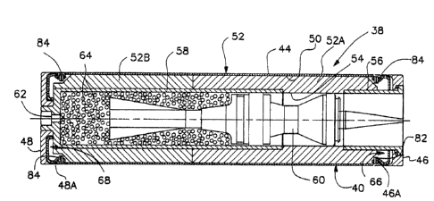
Turning now to Figs. 3-5, th2re is shown the
features o~ ~he present invention associated with a
cased telescoped ammunition round 38 for providing
improved end cap retention during firing and end cap
retraction after firing to ensure dimensional recovery
o~ the tubular case 40 of the round after firing of a
projectile therefrom so tha~ the case can be ejected
f rom the gun chamber .
The elongated tubular case 40 of the improved
round 38 includes a case skin tube 44 and a pair of
forward and aft end caps 46, 48 on opposite ends of the
tube. The tubular case 40 defines a chamber 50 that
contains a propellant charge 52 having an axial bore
54. Separate forward and aft tubes 56, 58 (such as a
forward ero~ion inhibitor tube and an aft conkrol tube)
are disposed in the case 40 extending at least
partially through the axial hore 54 of the propellant
charga 52 ~rom respective ~orward and aft ends of the
bore. The separate ~orward and a~t tubes 56, 58 are
attached, such as by being threadably fastened,
respectively to the forward and aft end cap~ 46, 48 of
the ca~e 40.
A projectile 60 spans between and is housed
within the ~eparate tubes 56, 58 and within the axial
bore 54 o~ the propellant charge 52. A primer 62 along
with loose propellant charge 64 are disposed within an
324533
-12-
`~ aft end of the aft tube 58. The primer 62 is
actuatable for igniting the loose propellan~ charge 64
to cause initial propulsion o~ the projectile 60
forwardly through the aft tube s8. Once the projectile
60 passes the forward end of the aft tube 58, the main
propellant charge 52 is expo~ed and ignited which, in
turn, causes the main ~iring of the projectile
forwardly from the case 4Q and the gun barrel (not
shown).
' The features of the present invention
1 genexally relate to internal forward and a~t ~lexure
:i springs 66, 58, each being spider-like in
configuration, provided in forward and aft ends of the
case 40. The flexure sprin~s 66, 68 have slightly
'~ different configurations and are associated with the
~;~ opposite forward and aft rims or ends 70, 72 of the
' case skin tube 44 a~d with the forward end of the
j: ~orward ~ube 56 and the aft end of the a~t ~ube 58,
~::
~ djacent re~pectivs forward and aft end caps 46, 48.
:.
The ~lexure spring~ 66, 6~ are capable of resiliently
~:~ and yi~ldably flexing to provide positive end cap
j:, retention during firing and ef~ective end cap
,~ retraction a~ter ~iring of the round 38 to ensure
3 ~: dimensional recovery of the tubular case 40 after
firing of the prsjectile 60 so that the case can be
;~ readily e~ected from the gun chamber.
s~ : More particularly, as ~een in ~igs. 6-9 in
~ ~ add1tion to Figs. 3-S and 10-12, the forward and a~t
.
!
13~33
-13-
flexure springs 66, 6B have respective outer peripheral
annular ring-like base portions 66A, 68A attached by a
plurality of fastening means at the interior of the
respective forward and aft ends 70, 72 of the case s~in
tube 44. The springs 66, 68 also have respective
pluralities of spring finger portions 66B, 68B
connected to the respective ba~e portions 66A, 68A and
projecting radially inwardly therefrom which, at inner
tips 66C, 6~C thereof, are engaged with or anchored to
respectively the forward end of the forward tube 56 and
the aft end of the aft tube 580
Tha plurality of Pastening means are
circumferentially spaced about the base portions 66A,
68A of the respactive springs 66, 68 and the respective
skin tube Pnds 70~ 72 ~or rigidly attaching the same
togeth2r. More particularly, the fastening means
includes respective forward and aft pluralities of
aligned circumferentially spaced holes 74, 76 and 78,
80 for~ed in the spring base portions 66A, 68A and skin
tube ends 70, 72~ Also, forward and aft pluralities of
rivet~ 82, 84 extend through and fasten the forward and
aft spring base portions 66A, 68A and skin tube ends
70, 72 together at ~he respective pluralities of holes
74, 78 and 76, 80 formed therein. The base portion
66A, 68A of each spring 66, 68 and each skin tube end
70, 72 fastened thereto are generally concave-shaped in
cross-section such that the skin tube ends seat in the
respective spring base por~ions. Further, ~orward and
,. . . . . . .. . . . . . . . .
~32~3~
.
-14-
a~t end caps 46, 48 has respective inner annular rims
46A, 48A which overlies the respective seated forward
and aft spring base portions 66A, 68A and skin tube
ends 70, 72 where the latter are ~astened together by
the fastening means.
The configurations of the springs 66, 68
differ from one another in the respective lengths and
shapes of their spring finger portions 66B, 68B. Each
spring finger portion 66A of the forward flexure spring
66 iæ generally linear-shaped in cross-section and its
inner tip 66C is snap fitted in a groove 86 ~ormed
circumferentially about the exterior oX the forward
tube 56 to more or le~s attach or anchor the forward
spring 66 to the forward tube 56. Each spring finger
portion 68A of the aft flexur2 spring 68 is longer than
each spring ~inger portion 66A of the forward flexure
spring 6~ and is generally bent inwardly away from the
a~t end cap 48 and toward aft end of the aft tube 58.
Thus, th~ aft:spring 68 is more or less captured
betwe~n the aft end cap 48 and aft end of the aft tube
~8- .
. In summary, therefore, the internal
spider-lik~ flexure springs 66, 68 are attached to
respective forward and a~t ends 70, 72 of the skin tube
44,~detachably anchored to the respective forward end
of the forward tube 56 and aft end o~ the aft tube 58,
and disposed adjacent to and internally of respective
orward and a~t end cap 46, 48 for ensuring retention
::
.
: .
: : ' .
-~ ~3%~3~
-15-
of the end caps on the skin tube ends during projectile
fixing. The springs 66, 68 are resiliently and
yieldably glexible for allowing axial movement of the
forward and aft end caps 46, 48 and their inner rims
46At ~8a away from the respective ~orward and aft skin
tube end~ 70, 72 during projectile firing, to the
displaced positions shown in Figs. 10-12. However,
these same properties of the springs 66, 6~ cause
retraction of the end caps 46, 48 and their respecti~e
rims 46A, 48A back toward the respective skin tube ends
70, 72 after projectile ~iring, to the positions shown
in Fig 3-5, to ensure dime~sional recovery of the
case 40 a~ter such firing for facilitating ejection of
the case ~rom a gun chamber. Thuæ, the intexnal
spring~ 66, 68 draw the e~d caps 46, 48 back toward
their original positions, seen in Figs. 3-5, after
firing and retain them during ejection.
Assembly of the round 10 would preferably
occur in the following sequence: (l) The primer 62 is
ins~alled into the aft ~ube (control tube) 58. ~(2)
Loose propellant charge 64 and the projectile 60 are
in~talled in the aft tube 58. (3j The aft spring 66
i~ riveted onto the a~t end of the skin tube 44. (4)
The aft end cap 48 is slid over the aft skin tube e~d
72. (5) The a~t tube/primer~loose propellant/
projec~ile subas~embly is in~erted into the aXt end
cap/aft spring/skin tu~e subassembly and threaded into
the aft end cap 48. t6) The aft propellant charge
:
-
` 13~3~
-16-
portion 52B is slid into the skin tube 44 over the aft
tube 58, ~ollowed by the forward propellant charge
portion 52B. ~7) The forward spring 66 i~ riveted
onto the forward end 70 of the skin tube 44. (8) An
erosion inhibitor is placed into the bore 54 in the
forward propellant charge portion 52A. (9) The
forward end cap 46 is place~ over the ~orward end 70 of
~he skin tube 4~. (10) A tolerance seal 8~ is slid
onto the forward tube (erosion inhibitor tube) 56.
(113 The forward tube 56 is inserted into the bore 54
o~ the forward propellant charge portion 52A and is
pushed in until the forward spring finyex portions 66B
snap into the annular groove 86 in the exterior of the
forward tube 56. 112) Finally, the seams and exit port
of the forward end cap 46 are sealed.
It is thought that the pre ent inventio~
and many o~ its attendant advantageq will ba understood
fro~ the foregoing description and it will be apparent
that various changes ~ay be made in the form,
construction and arrangement of the parts thereof
without departing from the spirit and scope of the
inYention or sacri~icing all of its material
advantagss, the ~orm hereinbefore described being
meraly a preferred or exemplary embodiment thereof.