Language selection

Search

Patent 1324894 Summary

Third-party information liability

Some of the information on this Web page has been provided by external sources. The Government of Canada is not responsible for the accuracy, reliability or currency of the information supplied by external sources. Users wishing to rely upon this information should consult directly with the source of the information. Content provided by external sources is not subject to official languages, privacy and accessibility requirements.

Claims and Abstract availability

Any discrepancies in the text and image of the Claims and Abstract are due to differing posting times. Text of the Claims and Abstract are posted:

  • At the time the application is open to public inspection;
  • At the time of issue of the patent (grant).
(12) Patent: (11) CA 1324894
(21) Application Number: 595362
(54) English Title: METHOD AND APPARATUS FOR THE IDENTIFICATION OF PARTICLES
(54) French Title: METHODE ET APPAREIL D'IDENTIFICATION DE PARTICULES
Status: Deemed expired
Bibliographic Data
(52) Canadian Patent Classification (CPC):
  • 340/140.1
  • 73/51.5
(51) International Patent Classification (IPC):
  • G01N 15/14 (2006.01)
  • G01N 15/10 (2006.01)
  • G01N 21/47 (2006.01)
(72) Inventors :
  • BEZANSON, DONALD S. (Canada)
(73) Owners :
  • MARITIME SCIENTIFIC SERVICES LTD. (Canada)
(71) Applicants :
(74) Agent: MACRAE & CO.
(74) Associate agent:
(45) Issued: 1993-12-07
(22) Filed Date: 1989-03-31
Availability of licence: N/A
(25) Language of filing: English

Patent Cooperation Treaty (PCT): No

(30) Application Priority Data: None

Abstracts

English Abstract


ABSTRACT
Apparatus for analysing particles in which the
particles traverse a sensing zone one at a time. A first
detector measures variations in the conductivity of the fluid
caused by the presence of a particle in the sensing zone. A
laser irradiates the sensing zone and a second detector is
provided responsive to light scattered by particles in the
sensing zone. Additional detectors are provided responsive
to fluorescence from the particles. The signals from each of
the detector means are digitized and stored and then
compared. The differences in successive waveforms from each
detector indicate the presence of abnormal particles.
Waveform shape is also used as an indication of the shape of
the particles.


Claims

Note: Claims are shown in the official language in which they were submitted.


THE EMBODIMENTS OF THE INVENTION IN WHICH AN EXCLUSIVE
PROPERTY OR PRIVILEGE IS CLAIMED ARE DEFINED AS
FOLLOWS:
1. Apparatus for the detection and analysis
of particles in a sample fluid comprising, means
defining a flow path for the fluid whereby the
particles traverse a restriction followed by a sensing
zone immediately downstream from the restriction one
at a time, electrical sensing means measuring
conductivity variations in the flow path caused by the
presence of a particle in the restriction, means
irradiating the sensing zone with a laser, first
detector means responsive to light scattered by the
same particle in the sensing zone, second detector
means responsive to fluorescence from the same
particle in the sensing zone, characterized by means
simultaneously digitizing the signals from the
electrical sensing means and from each of the detector
means at selected intervals over the time the particle
is in the sensing zone, means storing sequences of the
digitized signals, and means displaying the stored
waveforms of the detected signals whereby the nature
of the particle can be determined.
2. Apparatus as set out in claim 1, further
including means analyzing the stored waveforms and
means responsive to the analysis of the waveforms for
controlling further signal processing.
3. Apparatus as set out in claim 1, further
including decision means adapted to accept or reject


the signals and means storing the accepted signals,
whereby different ranges of particle characteristics
can be examined.
4. Apparatus as set out in claim 1, claim 2
or claim 3, further including means comparing
successive waveforms from each detector, whereby the
presence of abnormal particles can be detected.
5. Apparatus as set out in claim 1, claim 2
or claim 3, wherein said second detector means
comprises a first detector responsive to shorter
wavelengths and a second detector responsive to longer
wavelengths in the fluorescence.
6. Apparatus as set out in claim 1, claim 2
or claim 3, wherein the flow path in which the
particles traverse a restriction is provided by a
selected first or second flow cell, each having an
aperture through which the sample fluid passes, the
first flow cell having a smaller aperture than the
second and further including a screen through which
the sample fluid flows before entering the first flow
cell to remove particles larger than the aperture.
7. Apparatus as set out in claim 1, claim 2
or claim 3, wherein said electrical sensing means
includes electrode means causing a current to flow
across the aperture and means sensing the resulting
voltage across the aperture.
8. A method for the detection and analysis of
particles in a sample fluid comprising, the steps of


defining a restricted flow path for the fluid
including a restriction followed by a sensing zone in
the flow path immediately downstream from the
restriction traversed by the particles one at a time,
measuring conductivity variations in the flow path
caused by the presence of a particle in the
restriction, irradiating the sensing zone with a
laser, detecting light scattered by the same particle
reaching the sensing zone, detecting fluorescence from
the same particle in the sensing zone, characterized
by the further steps of simultaneously digitizing the
detected signals and the conductivity measurement at
selected intervals over the time the particle is in
the sensing zone, storing sequences of the digitized
signals, and displaying the stored waveforms of the
detected signals whereby the nature of a particle can
be determined.
9. A method as set out in claim 8 further
including the steps of analyzing the waveforms and
controlling further signal processing based on this
analysis whereby the nature of a particle can be
determined.
10. A method as set out in claim 8 further
including the steps of determining if the signals are
within acceptable ranges, storing such signals as are
determined to be in acceptable ranges and rejecting
others whereby ranges of particle characteristics can
be examined automatically.

11

11. Apparatus for the detection and analysis of
particles in a sample fluid, comprising: means defining
a sample fluid flow path having a restriction
immediately followed by a sensing zone downstream from
and spaced from said restriction, wherein particles in
the sample fluid traverse said restriction and said
sensing zone one at a time; electrical sensing means
measuring electrical conductivity variations in the flow
path caused by the presence of a first particle in the
restriction; means irradiating the sensing zone with a
laser; first detector means responsive to light
scattered by the same first particle when it reaches the
sensing zone; second detector means responsive to
fluorescence from the same first particle in the sensing
zone; means digitizing and storing individually the
signals from the electrical sensing means and from each
of the detector means; and means displaying the stored
signals as waveforms whereby the nature of the particle
can be determined.
12. Apparatus as set out in claim 11, further
including means comparing successive waveforms from each
detector, whereby the presence of abnormal particles can
be detected.
13. Apparatus as set out in claim 11 or claim 12
wherein said second detector means comprises a first
detector responsive to shorter wavelengths and a second
detector responsive to longer wavelengths in the
fluorescence.

12

14. Apparatus as set out in claim 11 wherein the
restriction in the flow path is provided by a f low cell
having an aperture through which the sample fluid
passes, the apparatus further including means providing
a flow of a sheath fluid around the sample fluid.
15. Apparatus as set out in claim 14 wherein the
restriction in the flow path is provided by a selected
one of first and second flow cells, the first flow cell
having a smaller aperture than the second, the flow path
including a screen through which the sample fluid flows
before entering the first flow cell to remove particles
larger than the aperture.
16. Apparatus as set out in claim 14 or claim 15
further including a collection tube downstream of the
sensing zone to separate the sample fluid from the
sheath fluid.
17. Apparatus for the detection and analysis of
particles in a sample fluid, comprising: a flow cell
having a restriction through which the sample fluid
passes, and a sensing zone immediately downstream from
and spaced from the restriction, said restriction and
said sensing zone being traversed by the particles one
at a time; means providing a flow of a sheath fluid
around the sample fluid; electrode means causing a
current to flow across the restriction; means sensing
the resulting voltage across the restriction, to measure
conductive variations in the fluid caused by the
presence of a particle in the restriction; means
irradiating the sensing zone with a laser; first

13

detector means responsive to light scattered by the same
particle in the sensing zone; second detector means
responsive to fluorescence from the same particle in the
sensing zone; and means digitizing and storing
individual signals from the electrode means and each of
the detector means, whereby the nature of the particle
can be determined.
18. Apparatus as set out in claim 14 further
including means for controlling back-pressure in the
sensing zone to avoid bubble formation at the
restriction and improve the sensitivity of the
measurement of the electrical conductivity variations
across the restriction.
19. A method for the detection and analysis of
particles in a sample fluid comprising the steps of:
defining a flow path for the fluid, the path including
a restriction followed by a sensing zone immediately
downstream from and spaced from the restriction, the
restriction being traversed by the particles one at a
time; measuring electrical conductivity variations in
the flow path caused by the presence of a particle in
the restriction; irradiating the sensing zone with a
laser; detecting light scattered by said particle
reaching the sensing zone to provide a scattered light
output waveform; detecting fluorescence from said
particle in the sensing zone to provide a fluorescence

14

output waveform; digitizing and storing individually the
output waveforms and the conductivity measurement; and
displaying the stored waveforms and conductivity
measurement whereby the nature of said particle can be
determined.
20. A method as set out in claim 19 further
including the step of measuring the peak value of the
stored waveforms, comparing the peak value with a
prescribed range and adjusting the flow rate of the
sample fluid to cause the stored waveform to fit within
the prescribed range.
21. A method as set out in claim 19 further
including the steps of comparing successive waveforms
from each detecting step whereby the presence of
abnormal particles can be determined.


Description

Note: Descriptions are shown in the official language in which they were submitted.


- ~32~894

This application relates to apparatus for the
detection and analysis of small particles in fluids and, in
particular, to apparatus of this type including circuitry for
the storage and processing of signals representing the
detected particles.
The apparatus of this invention is particularly
useful in the monitoring of industrial processes and the
identification of various particles without the intervention
of human operators. Typical applications are in oceanography
or industrial applications such as milk analysis~
It is known to use a Coulter detector to establish
particle size by having the particles carried in a conductive
liquid. When a particle encounters a restriction in its flow
path it displaces a significant amount of the conductive
liquid with a resulting change in conductivity giving an
indication of particle size. It is also known to detect and
analyse small particles and fluids by causing the particles
to traverse singly across t~e sensing zone irradiated by
coherent light from a laser. As shown in U.S. Patent
4,596,464 issued to Hoffman on June 24, 1986 scattered light
is detected and analysed to give information as to the
characteristics of a particle. The particles may also
fluoresce in the sensing zone and the resulting fluorescence
is similarly detected and analysed to give information about
a particle. This is shown in U.S. Patent 4,475,236 issued to
Hoffman on October 2, 1~84. If the particles are not
themselves fluorescent then an appropriate dye may be added
to the sample to produce fluorescence.
The present application relates to an improved


.

- ,

1324894
apparatus which enables the signal from each of the
conductivity, scattering and fluorescent detectors to
be stored as separate waveforms so that the various
waveforms relating to a single particle can be used as
a composite source of information to establish the
identity and characteristi~s of a particle.
Briefly expressed the present application
relates to apparatus for the detection and analysis of
particles in a sample fluid, comprising: means
defining a sample fl~id flow path having a restriction
immediately followed by a sensing zone downstream from
and spaced from the restriction, wherein particles in
the sample fluid traverse the restriction and the
sensing zone one at a time. Electrical sensing means
measure electrical conductivity variations in the flow
path caused by the presence of a first particle in the
restriction. A laser irradiates the sensing zone and
a first detector is responsive to light scattered by
the same first particle when it reaches the sensing
zone. A second detector is responsive to fluorescence
from the same first particle in the sensing zone.
Means are provided for digitizing and storing
individually the signals from the electrical sensing
means and from each of the detector means and
displaying the stored signals as waveforms whereby the
nature of the particle can be determined.
In its method aspect, the invention relates to
a method for the detection and analysis of particles

B rn/
~, , .

- 132~9~
2a
in a sample fluid. comprising the steps of; defini~g a
flow path for the fluid, the path including a
restriction followed by a sensing zone immediately
downstream from and spaced from the restriction, the
restriction being traversed by the particles one at a
time; measuring electrical conductivity variations in
the flow path caused by the presence of a particle in
the restriction; irradiating the sen~ing zone with a
laser; detecting light scattered by the particle
reac~ing the sensing Zone to provide a scattered light
output waveform detecting fluorescence ~rom the
particle in the sensing zone to provide a fluorescence
outp~t waveform; digitizing and storing individually
the output waveforms and the conductivity measurement;
and displaying the stored waveforms and conductivity
measurement whereby the nature of the particle can be
determined.
A particular embodiment o~ the invention will
now be described in conjunction with the accompanied
drawings in which:
Figure 1 is a diagram of the flow cell which
includes the sensing zone with Figure l(a) showing a
cross-section of the sensing zone;
Figure 2 is a diagram of the fluid supply
system;
Figure 3 is a block diagram of the data
processing and storage section; and
Figure 4 shows typical waveforms resulting from

rn/
lc- .

1324~94
particle detection.
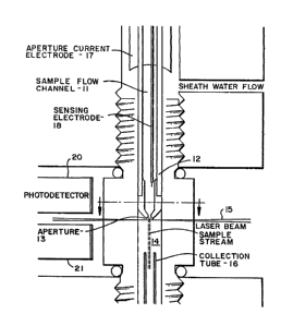
Figure 1 shows a flow cell formed from a body 10
defining a sample fluid channel 11 and a sheath fluid channel
12. The sample fluid passes through an aperture 13 which
controls the size of the sample stream and the resulting thin
stream, about 50-200 ~m diameter, passes through a sensing
zone 14 contained in a cuvette portion of the flow cell. A
transverse beam of radiant energy 15 from a laser 18 (Figure
2) passes through the sensing æone to illuminate particles
therein. A collectlon tube 1~ separates the sample f low from
the sheath fluid flow at the outlet so that the samples are
available for retesting.
Thus, the sample fluid is passed in a thin stream
through the sensing zone with the stream surrounded by a
sheath flow of clean fluid. As a result only one particle
traverses the sensing zone at any one time. Electrodes 17
are provided in contact with this sheath fluid and the sample
fluid. Sheath and sample water have a certain conductivity
and the electric current caused to flow through the orifice
between the electrodes 17 creates a voltage drop across it.
As a particle in the flow displaces conductive fluid, the
effective resistance of the orifice rises and the voltage
rises. This voltage change is sensed by electrode 18. The
ratio of the change in voltage to the background voltage is
recorded as sense as a measure to the volume of the particle.
In the sensing zone the laser beam is focused about
10 ~m along the streamline and about 100 ~m wide across it.
In the laser beam the particle scatters light and any
fluorescent material in it fluoresces at a characteristic


. . ' ~

132~89~

colour and intensity. The scattered light is detected by two
or more photodetectors 20, 21 adjacent to the exiting beam
and almost colinear (in the range 1-20) with the input beam.
Fluorescent light emitted is conical detection zones at right
angles to the input beam is gathered by condensing lenses
(not shown) and transmitted to photomultiplier tubes (not
shown) to amplify the low amounts of energy in this signal.
These detectors are responsive to different wavelengths,
typically one in the red ends of the spectrum and one in the
green.
The collection tube 16 serves to collect the sample
particles which have passed through the sensing zone so that
they are then available for retesting. In the sensing zone
the particles are travelling at a higher velocity than the
sheath fluid and accumulate in tube 16. By controlling the
rate of withdrawal at the outlet of tube 16 a sample fluid
flow close to that of the original is obtained.
A block diagram of the system including sensors,
interface, computer, and fluid control system is shown in
Fig. 2. The triangular elements, such as valve 34, are
computar-controlled solenoid valves. Fluid is driven by
computer-controlled stepper motors, such as motor 44,
connected to syringe pumps, such as pump 45. Beaker shapes
indicate sources of fluids outside the machine, such as
sample source 33. Connections from the computer to the
solenoids and motors, and from pressure sensors, are not
shown.
Sheath fluid is drawn from a source 30 through
solenoid control valves 31 and 32 to be injected into the


1 3 ~
flow cell. The f:Low is controlled by pump 45 which has a
variable rate, typically operating at 1 stroke/minute. Two
flow cells are shown, one equipped with a screen 50 to
exclude potentially clogging particles and having a small
diameter orifice for measuring small sized particles. The
other is for measuring larger particles. Valve 32 selects
between the flow cells for the sheath fluid and valve 37
selects between the cells for the sample fluid. The sample
fluid is drawn from a source 33 through control valves 34,
35, 36 and 37 and is also injected into the selected flow
cell. The sample fluid flow is controlled by pump 51. If
reguired, the sample can be mixed with stain from a source 40
supplied to a mixing chamber 43 via valves 41 and 42 under
control of pump 52. The mixing is achieved by supplying
sample fluid to the mixing chamber via line 53 through valve
36. Once mixed, the fluid is returned along the same line to
be fed to the flow cell.
Thus, in operation, sample fluid and sheath fluid
are first drawn into their respective syringe pumps and the
valves repositioned for injection into one of the two flow
cells, one for small, one for large particles. Sample and
sheath are then pumped through at optimum rates. Sample
pumping rate determines the rate of particle detection which
is usefully the maximum below interface overload. The sheath
pumping rate controls particle speed in the sensing zone and
may be varied with particle size range for optimum waveform
resolution. Rather than using collection tube 16 the fluid
mix can pass to a receiving syringe pump 60 which moves in
tandem with the input pumps, while generating a constant


s

-- 132~894
backpressure through a compressed spring. This reduces
bubbling across the orifice plate and passes higher currents
to be used in electrodes 17, heading to operator sensitivity.
The connection 61 between source 30 and valve 34 permits the
flushing of stain solution.
Referring now to th block diagram of Figure 3, four
analog boards 70 are provided, typically connected to the
conductivity signal, the scatter signal and the two
fluorescence signals. These signals are digitised and
transferred to buffers 71 and 72. At the same time a
determination if the signals are within preset limits is made
in board 73 and appropriate control signals supplied to board
74 to control the valves and pumps~ Bus 75 and bus 76 are
connected to the computer for long term storage and signal
processing.
In detail, the signals are amplified through a
series of three amplifiers, providing four degrees of
amplification which may be selected for optimum digitisation.
After digitisation, signals are held in temporary memories 71
and 72 while other signals are being transferred by direct
memory access to the main computer via bus 75. Waveforms
having peak values within a preset range, or characteristics
as described in the following paragraph, are stored until a
certain number are counted and the volume pumped is noted.
Then, gains are changedt more sample fluid pumped, and a
different range of signal strengths recorded. This is
continued until an entire over-range is handled. At a point
within these ranges, flow shifts from a small sensor to a
large one. Electrical volume, that is conductivity


,

: . .

132~89~

measurement, is usually the parameter which determines
ranging, so that the system covers a complete spectrum of
microscopic diameters, with a set number counted in each
range. This provides particle information with the same
statistical validity in each size range. Current particle
counters typically generate counts of variable validity
because of differences in the numbers counted in each range.
In known apparatus, only the peak value of each signal is
recorded, and the values are stored separately as counts in
sets of channels ("channelysers"). In the system of this
invention, four or more signals are digitized simultaneously
at variable intervals (typically one microsecond) over the
time the particle is in the sensing zone. This produces four
or more stored waveforms, associated with each particle,
which are retrieved and analysed later to identify the
particle. The shapes of the waveforms and comparison between
the signals for an individual particle are useful for making
precise identification of types of particles. As an example
of this, reference may be made to Figure 4. The upper trace
is from the green end of the fluorescent measurement spectrum
and represents the entire particle. The next trace from the
red end represents only a portion of the body which responds
in this region of the spectrum. The scattered light trace
shown next gives a measure of the surface characteristics of
the body. The aperture voltage or volume measurement shown
in the lower trace is typical of that for a smaller particle~
Peak detection is used for establishing signal
ranges for digitisation. Peak values of signals are applied
to threshold the gates whose output states are connected


~324~9~

through programmable logic circuitry to panel display lights
and alarm controls, and counting circuitry. In cases where
particle identity can be determined by an algorithmic
combination of the various peak values, this feature provides
rapid indication of the presence of identified particles,
without the need for waveform analysis. Algorithms are also
be used in this way by the control logic board 77 to decide
whether or not to store a given set of waveforms. In many
cases, samples contain large numbers of particles which are
of no interest. Rejection of their waveforms at this
preliminary stage results in more efficient use of limited
computer memory.


. . , ,. : - ..... ...

Representative Drawing
A single figure which represents the drawing illustrating the invention.
Administrative Status

For a clearer understanding of the status of the application/patent presented on this page, the site Disclaimer , as well as the definitions for Patent , Administrative Status , Maintenance Fee  and Payment History  should be consulted.

Administrative Status

Title Date
Forecasted Issue Date 1993-12-07
(22) Filed 1989-03-31
(45) Issued 1993-12-07
Deemed Expired 1998-12-07

Abandonment History

There is no abandonment history.

Payment History

Fee Type Anniversary Year Due Date Amount Paid Paid Date
Application Fee $0.00 1989-03-31
Registration of a document - section 124 $0.00 1989-09-28
Maintenance Fee - Patent - Old Act 2 1995-12-07 $50.00 1995-11-16
Maintenance Fee - Patent - Old Act 3 1996-12-09 $250.00 1997-11-19
Owners on Record

Note: Records showing the ownership history in alphabetical order.

Current Owners on Record
MARITIME SCIENTIFIC SERVICES LTD.
Past Owners on Record
BEZANSON, DONALD S.
Past Owners that do not appear in the "Owners on Record" listing will appear in other documentation within the application.
Documents

To view selected files, please enter reCAPTCHA code :


To view images, click a link in the Document Description column. To download the documents, select one or more checkboxes in the first column and then click the "Download Selected in PDF format (Zip Archive)" or the "Download Selected as Single PDF" button.

List of published and non-published patent-specific documents on the CPD .

If you have any difficulty accessing content, you can call the Client Service Centre at 1-866-997-1936 or send them an e-mail at CIPO Client Service Centre.


Document
Description 
Date
(yyyy-mm-dd) 
Number of pages   Size of Image (KB) 
Drawings 1994-07-16 4 86
Claims 1994-07-16 7 232
Abstract 1994-07-16 1 19
Cover Page 1994-07-16 1 18
Description 1994-07-16 9 341
Representative Drawing 2002-05-03 1 10
Examiner Requisition 1992-01-22 1 53
Prosecution Correspondence 1990-04-04 2 37
Prosecution Correspondence 1992-05-20 5 139
PCT Correspondence 1993-09-08 2 42
Office Letter 1989-06-08 1 67
Fees 1995-11-16 1 45