Note: Descriptions are shown in the official language in which they were submitted.
- 1 ~32~297
Title of the Invention
METHOD AND DEVICE FOR CONTROLLING A MATRIX SCREEN DISPLAYING
GRAY LEVELS
Backqround of the Invention
DESCRIPTION
The invention relates to a method and device for
controlling a display matrix screen adapted to display images
having gray levels. It applies more particularly to the
control of microdot fluorescent screens or liquid crystal
screens. The images can be in black and white or in colour,
the term gray level meaning in the latter case colour half-
tone.
To control the displaying of images on a matrix screen,
the following method of sweep is generally used: the lines
are successiv~ly addressed - i.e.. taken from one appropriate
potential Vlp to another appropriate potential Vla - once per
image and for a time T (line time) which is identical for all
the lines and is equal to the quotient of the duration of an
image by the number of lines; sim~ltaneously with the
addressing of each line, the columns receive signals allowing
the control of the_respective states of the image elements,
or pixels, of the line in question, as a function of the
required image: a column is taken to an appropriate potential
Vca if the corresponding pixel i~ to be illuminated, and to
another appropriate potential Vce if on the other hand the
corresponding pixel is to be extinguished. At the end of the
. , ~ . .
. . . . .
- 2 - 132~297
time T, the addressing of the line in question ceases and the
following line is addressed, the signals received by the
columns depending on the respective required states of the
pixels of this following line. and so on.
Techniques are also known allowing the production of
images comprising gray levels:
A first technique consists in subiecting a column to a
potential intermediate between Vca and Vce, so that the
corresponding pixel has an intermediate brightness between
that correspondi-ng to the illuminated pixel and that
corresponding to the extinguished pixel.
However. more particularly in the case of a microdot
fluorescent screen, it is very difficult to control an
intermediate voltage between Vca and Vce for a given
brightness. because of the rigidity of the voltage/brightness
characteristic of such a screen.
The second technique consists in taking a column to the
potential Vca for only a fraction of the line time
proportional to the quantity of light required for the
corresponding pixel and in then returning the column to the
potential Vce for the remainder of the line time (time
modulation of the control potential of each column).
However, the relation between the time of application of
Vca and brightness is not fully linear and, more particularly
in the case of a microdot fluorescent screen, there is a
strongly non-linear relation between the time of application
and brightness, because of the time for establishing the
.
.. : . . ~ . .. . . . . : .
- . :- . . : . : : : :::
:. . - ~ . .. , :
: - . -
-
~3232~7
-- 3 --
voltage at the terminals of a pixel.
~ oreover, in the case of one or other of the two
aforementioned known techniques, the time for establishing
the voltage at the terminals of a pixel also depends on the
resistance of access to such pixel connected with its
position in the screen. Consequently, the charge time of the
pixel also depends on that position: for the same control
potential two pixels. for example, situated at the two ends
of the same column do not have the same brightness, the pixel
closest to the column contact to which the control potential
is applied havlng the strongest brightness.
Brief statement of the Invention
The invention relates to a process and apparatus for
controlling a matrix screen displaying gray levels, which use
a time modulation of the control potential of each column and
do not therefore have the disadvantage of the first afore-
mentioned known technique, neither do they cause any problems
of non-linearity, like the second aforementioned technique.
More precisely, the invention first of all relates to a
method of controlling a display matrix screen adapted to dis-
play images whose image elements have gray levels, the gray
levels being located by integers i progressively increasing
from C to an integer m at least equal to l, the screen com-
prising a plurality of lines and a plurality of columns whose
intersections are respectively associated with image ele-
ments, wherein for each image the lines are successively
activated for a given time T, known as the line time and
.. ~ . .
,. :
- ,: ~ ,...
. - , ' ~- ' ~.
132~2~7
4 --
identical for all the lines, and on the activation of each
line the columns are simultaneously and respectively con-
trolled by signals adapted to activate the columns, each
signal being applied for a time which depends on the gray
level of the image element corresponding to the intersection
of the activated line in question and the column controlled
by the signal in question, wherein the line time T is sub-
divided into N equal intervals of time dt, N being an integer
at least equal to m, wherein for each line and for each of
the gray levels i of said line a gray level i is respectively
associated with a selected integer Nil of intervals dt, l
representing the number of the line in question, the numbers
Nil forming for every fixed l a strictly increasing sequence
of the variable i, of first term NOl zero and of last term
Nml lower than or equal to N; and the time during which said
signal is applied is equal to the product of dt by that
number of said sequence which corresponds to said line and
said gray level. said column being deactivated after said
time during which said signal is applied. until the
activation of the following line. the numbers Nil being so
selected as to obtain a predetermined distribution for light
intensities of the different gray levels.
Clearly. therefore, the invention allows the correlation
of the time of application of the potential Vca during the
line time with the voltage~brightness characteristic of the
screen in que~tion.
The use of the Nil quantities according to the invention
and the possibility of selecting such quantities means that
f~.',;,
,
,. ,, : ., .
132~297
I - 5 -
it ls possible subsequently - i.e., when the screen and the
electronic circuits associated therewith are ready to operate
or have even already operated - to balance the obtained gray
levels in relation to one another, either to obtain a
particular, regular or logarithmic scale of gray, for
example, or to compensate edging of the screen/circuits
assembly, or to select a better compromise between coupling
and brightness~
It should be remembered in this respect that the
coupling in question is a phenomenon bound up with the
resistance-of access to different pixels and takes the visual
form of "burr" from one screen line to another.
For every couple of lines 11 and 12, the sequence of
numbers Nill and Nil2 can be identical (non-differentiation
of the screen lines), the lines 11 and 12 not necessarily
being successive lines.
In that case the gray levels can be controlled as
follows:
- at least two zones corresponding to the gray level O
and the gray level m respectively are formed on the screen,
- the fraction of line time during which the column~
are activated for the image elements with gray level m is
varied until a desired image quality is obtained on the
screen,
- a uniform image is formed on the screen which has the
gray level m thu~ defined. and the brightness of such uniform
image is measured,
- 6 - ~32~2~7
- from such measured brightness value that brightness
is calculated which must be obtained for each of the other
gray levels 1 with m-1, as a function of a selected scale of
gray levels, and
- for each of the other gray levels a uniform image is
formed on the screen which has the other gray level, and the
number of said sequence corresponding thereto is so adjusted
as to obtain the calculated brightness for said other gray
level,
On the other hand, for certain lines 11, 12 of the
screen, the sequences of numbers Nill and Nil2 may not be
identical tdifferentiation of the screen lines).
In that case the tirne of application of the potential
Vca during the line time can be correlated not only with the
voltage/brightness characteristic of the screen. as already
indicated. but also with the position of the pixel addressed
in the screen.
When the sequences Nill and Nil2 are not identical for
certain lines 11, 12 of the screen, the maximum gray levels
can be controlled as follows:
- the respective brightnesses of all the lines of the
screen are measured when said lines are at the maximum gray
level. and the weakest brightness line is determined, which
is taken as a reference, and
- for each of the other lines 1 the number Nml
corresponding to the maximum gray level is so adjusted that
the resulting brightness is equal to the reference
brightness.
: , ' . .
132~2~7
-- 7 --
In that case the other gray levels 1 to m-1 can then be
controlled ac follows:
- from such measured brightness value that brightness
is calculated which must be obtained for each of the other
gray levels 1 with m-1 as a function of a selected scale of
gray levels and
- for each of the other gray levels a uniform image is
formed on the screen which has the other gray level. and the
number of said sequence corresponding thereto is so adjusted
as to obtain the calculated brightness for said other gray
level.
Preferably Nml is lower than N something which enables
the "burr" from one line to ~nother to be eliminated as will
be more clearly shown hereinafter.
The invention also relates to an apparatus for con-
trolling a display matrix screen adapted to display images
whose image elements have gray levels, the gray levels being
located by integers i progressively increasing from 0 to an
integer m at least equal to 1, the screen comprising a
plurality of lines and a plurality of columns whose inter-
sections are respectively associated with image elements,
the device comprising:
- means provided for successively activating the lines
during a given time T known as the line time, which is
identical for all the lines and for each image, and
- means for simultaneously controlling the columns
which are provided to produce during the activation of each
line, signals adapted to activate the columns respectively,
r
~32~2~7
~ - 8 -
each signal being applied for a ti~e which depends on the
gray level of the image element corresponding to the inter-
section of the activated line in question and the column
controlled by the signal in question,
- the means controlling the columns comprising:
- means which are common to all the columns and
comprise:
. means provided to produce pulses of period dt equal
to T/N, N being an integer at least equal to m,
. memorizing means provided to memorize, for each line
and at least for each gray level i of said line which is not
zero, an information item connected with a selected integer
Nil, l denoting the number of the line in question, the
numbers Nil forming for any fixed l a strictly increasing
sequence of the variable i of last term Nml lower than or
equal to N, and
- means provided to apply said signal for a time equal
to the product of dt by that number of said sequence which
corresponds to said line and said gray level and to
deactivate said column after said time during which said
signal is applied. until the activation of the following
line. the application time of any signal corresponding to the
disp1ay of an image element of gray level O being zero, the
numbers Nil being so selected as to obtain a predetermined
di8tribution for the light intensities of the different gray
level8.
In a particular embodiment of the apparatu8 according to
the invention. the means for controlling the columns also
.~ .
.
132~297
g
comprise a shift register whose number of positions is equal
to the number of columns and which receives at its input
information items of gray level for the columns, each
position being associated with a given colurnn and occupied
during the activation of a line by the information item of
gray level i relating to such column, the means provided for
applying said signal comprising for each column:
- a register which receives at its input t,he
information item contained in the corresponding position of
the shift register and which is controlled by start-of-line
signals, and
- a comparator with two inputs, whose first input is
connected to the output of said register and whose output
controls the activation of the corresponding column via
amplification means, and
- the means common to all the columns are provided to
deliver to the second input of each comparator information
items representing integers k. such information items so
varying increasingly from O to m during the line time that
the column corresponding to the comparator is activated as
long as k is lower than i, then deactivated and maintained in
the deactivated state as soon as k reaches i until the
activation of the following line~
In a first particular embodiment of the apparatus
according to the invention the numbers Nill and Nil2 being
equal, for any couple of lines ll and 12 and for each gray
level i, the means common to all the columns also comprise:
'`
, .: .
.
: .. .-, : .
'
~32~2~7
-- 10 --
- a first counter provided for reverse counting, and
- a second counter which is zero reset when a line
starts and is incremented by an end-of-counting signal
emitted by the first counter and which delivers to the second
input of each cornparator the information items representing
the numbers k.
` the first counter being decremented by the means
provided for producing the pulses,
the memorizing means comprising at least m registers
numbered from 0 to m-l and an address bus to which the
information items representing the numbers k are delivered,
the output signals of the memorizing means controlling the
initialization of the first counter. which takes into account
said output signals during the emission of its end-of-
counting signal, and the information item presents at the
address i memorizing means, i taking any of the values 0 to
m-l being equal to the difference between the numbers
N(i+l)l and Nil.
Lastly, in a second particular embodiment, the sequences
of numbers Nill and Nil2 not being identical for certain
lines ll, l2 of the screen, the means, to all the columns
also comprise:
- a first counter provided for reverse counting,
- a second counter which is zero reset when a line
starts and is incremented by an end-of-counting signal
emitted by the first counter and which delivers to the second
input of each comparator the information items representing
'
: ,. . .. .
"
1325297
the numbers k, and
- a third counter which i5 zero reset at the start of
an image and incremented at each line start,
5the first counter being decremented by the means
provided for producing the pulses,
the memorizing means comprising at least mxL
registers, L being the number of lines, and an address bus to
which the information items are delivered which represent the
numbers k in the form of binary words in two parts, the part
of heavy weight corresponding to the output signals of the
third counter, and the part of lightweight corresponding to
the information items representing the numbers k, the output
signals of the memorizing means controlling the
initialization of the first counter, which takes into account
said out.put signals durina the emission of its end-of-
counting signal. and the information item presents at the
address ixl of the memorizing means, i takina. any of the
values 0 to m-1 and 1 taking any of the values 1 to L being
equal to the difference between the numbers N(i+1)l and Nil.
List of drawinas
The invention will be more clearly understood from the
following description of purely exemplary non-limitative
embodiments thereof. with reference to the accompanying
drawings, wherein:
Fig. 1 illustr~tes diagrammatically the principle of a
"all or nothing" display for a microdot fluorescent screen,
,
- . .
- 12 - 13232~7
Fig. 2 illustrates diagrammatically the principle of the
invention for such a microdot fluorescent screen.
Fig. 3 shows the variations in electronic current in
dependence on the voltage between the cathode and the grid
for a given screen of the preceding kind,
Fig. 4 illustrates diagrammatically the advantage
according to the invention of subdividing the line time T
into a number N of intervals dt higher than the maximum gray
level m,
Fig. 5 is a diagrammatic view of a first particular
embodiment of the apparatus according to the invention, and
Fig. 6 is a diagrammatic view of a second particular
embodiment of the device.
Descri~tion of the Dreferred embodiment
Fig. 1 illustrates diagrammatically the principle of
"all or nothing" display in the case of a particular microdot
fluorescent screen. The term "all or nothing display" means
a display in which each pixel can only be either in the
extinguished or the illuminated state, without an
intermediate state. Fig. 1 shows successive addressings of
the three first lines of the screen L1, L2 and L3. At a
given moment each line pdsses from a potential Vlp-45V to a
potential Vla-9OY, which it maintains during the line time T,
to then return to the potential Vlp-45V at the moment when
the following line passes from the potential 45V to the
potential 90V,.. When all the lines have been addressed, the
first line is addressed again, and so on.
: ~
- ' ' '' , ~.
132~297
- 13 ~
Fig. 1 also shows particular addressing 8 ignals of the
three first columns C1, C2 and C3 of the screen, the signal~
leading to the following image on the screen: pixels
corresponding to the intersections of the columns C1, C2 and
C3 with the line L1 are in the extinguished, illuminated and
extinguished states respectively; the intersections of these
columns with the line L2 lead to pixels in the illuminated.
extinguished and extinguished states respectively, and the
same intersections with the line L3 lead to pixels in the
illuminated, extinguished and illuminated states
respectiveiy. Thus, for example, when the line L1 is
activated, the potential applied to the contact of the column
Cl passes from Vce-OV to Vca-45V. then returning to OV during
the successive addressings of the lines L2 and L3.
The method according to the invention will now be
described: according to the invention the line time T is
divided into N equal intervals dt. Let it be supposed that a
display capacity is required of m+1 gray levels located by
the number 0 (pixel extinguished), 1, ..., m (maximum gray
level corresponding to an illuminated pixel). The number N
is at least equal to m, In practice, N is much larger than m.
A number Nil of intervals dt is associated with each gray
level i of each of the lines 1 of the screen. The gray level
0 (pixel extinguished) is associated with interval 0,
whatever the number l of the line may be. In other words,
N01 is zero, whatever l may be.
Moreover the number of intervals dt associated with each
-;
~ ~ 2 ~ 7
- 14 -
of the gray levels increases strictly with the brightness of
such gray level. In other words, for any fixed l, the
sequence of numbers Nil is a strictly increasing sequence of
the variable i.
Moreover, the maximum gray level m (corresponding to an
illuminated pixel) is associated with a number of intervals
Nml lower than or equal to N, whatever l may be.
For a given addressed line, the column electrode whose
pixel must have a brightness of gray level i which is not
zero is taken, at the start of the line time T, to the
activation potentiai Vca (OV for certain microdot fluorescent
screens) an~ maintained at such potential for Nil intervals
of time dt, l being the number of the line in question.
whereafter the electrode is returned to the extinction
potential Vce t45V for microdot fluorescent screens) until
the start of the following line.
The method according to the invention is illustrated by
Fig. 2, showing the case of a particular microdot fluorescent
screen: in this example the line time T is subdivided into 32
intervals dt (a) with a view to expressing 3 gray levels (0
to 7), The numbers N and m are therefore equal to 32 and 7
_ respectively.
Four gray levels 0. 1, 4 and 7 are considered, and for
each of these levels the time graph is shown of the control
signal applied to a column contact to display such level (in
chain lines) and also the behaviour of such column (in
continuous lines) during the line time T. It will be noted
; ~ ;
' , ~` ' .
132~2~7
- 15 -
that in Fig. 2 the gray level 7 ("white" - i.e., illuminated
points) corresponds to N71~28 intervals dt (b), 1 denoting
the number of the line in question, but the gray level 4 is
associated with N41-14 intervals dt (c). that the gray level
1 (pixel almost extinguished) is associated with N11 5
intervals dt (d), and that the gray level 0 tblack dot -
i.e., extinguished) is associated with N01-0 interval dt (e).
An example showing the improvement of the performance of
a microdot fluorescent screen by the method according to the
invention is given in Table I, which is to be found at the
end of the description, and wherein the lines are not
differentiated: for any couple of lines 11, 12 and for each
gray level i the numbers Mill and Nil2 are equal.
In Table 1 the gray levels extend from 0 to m=15, the
numbers Nil associated therewith according to the invention
ranging from Nol-0 to N151-355. The gray levels obtained
with a regular distribution in time in the second
aforementioned known technique (application time of Vca
proportional to the required brightness) are also compared
with the gray levels obtained with an adjusted distribution
according to the invention for a microdot fluorescent screen
whose emission characteristic is shown in Fig. 3. The charge
resistancç of each column of the screen is 10 kilo-ohms, the
charging capacity per column being 1 nanofarad, the line time
being 64 microseconds, and the line time being subdivided
into N-640 equal intervals dt.
Fig. 3 shows the variations in the intensity J of the
electronic current expressed in milliamps per square
.
'`' . ' '
-' ' : , : ~. .
. . .
-~:.- . , , , . . :
132~297
- 16 -
millimetre as a function of the voltage v between a cathode
(column) and a grid (line~ of the screen, expressed in volts,
Table I indicates for each gray level i the value
obtained for the ratio (in per centl of the brightness Ii
corresponing to such gray level and the brightness
corresponding to the maximum gray level (15), on the one hand
with the invention. by experimentally determining the numbers
Nil so as to obtain a regular distribution of brightness. and
on the other hand with the prior art (second aforementioned
known technique).
It will be noted that the invention allows the obtaining
of brightness ratios which increase substantially in
arithmetical progression. something which is not the case in
the prior art.
Moreover. with the reaular distribution of brightr,ess
according to the invention as shown in Table I. the coupling
is limited to 2.7% of the current emitted by a dot of gray
level 15. such coupling being ~ero for the other levels 0 to
14.
Fig. 4 shows diagrammatically the advantage of not
attributing N intervals dt to the maximum gray level m. A
line a of a microdot fluorescent screen and the following
line l+1 are considered. It is supposed that a pixel PB of
line l corresponds to an illuminated point (gray level m) and
that the pixel PN belonging to the same column as PB and
situated on the line 1+1 corresponds to an extinguished dot
(gray level 0). In case (a). in which N intervals dt are
.
. : . - ::
. . , .. :: - ~ : . .:
: ~ . :, ,.--
... ;. .. : , -- : .... ;: ::
132~297
- 17 -
attributed to the most important gray level, it can be seen
that their exists a coupl ing CPL between the pixels PB and
PN. the chain lines corresponding to the control signal
applied to the contact of the column in question. and the
solid line corresponding to the behaviour of such column
during the line time T. Because of this coupling. light is
emitted parasitically on the line l+1. In contrast. in the
case (b). in which the number of intervals dt attributed to
the most important gray level is lower than N, there is no
such parasite emission.
~ n explanation will now be given of how to determine the
number of intervals Nil to be associated with each gray level
i. We shall first consider the case in which the lines are
not differentiated. The numbers Nil can be determined as
follows:
- the imaqe of a chessboard. or a successic,n of
alternately illuminated bands (maximum gray level) and
extinguished bands (0 gray level) is formed on the screen.
It is enough to form an image comprising an extinguished part
- and an illuminated part. and more precisely an image
comprising at least on one column an illuminated point
immediately followed by an extinguished point.
Then the fraction of line time is varied during which
the electrodes of the columns are maintained at the
activation potential for the illuminated pixels, either by
varying Nml with a constant N, or by varying N with a
constant Nml. In this way the best compromise is sought
,
"~
- 18 - ~32~2~7
between the coupling and brightness, knowing that in
proportion as Nml/N is greater, brightness is better but
coupling is stronger.
Then a uniform image of ~ray level ~ resulting from the
precedin~ compromise is formed on the screen and the
brightness of the image is measured. for example. by a
photctometer or by measurirlq the anode current (in the case
of a microdot fluorescent screen).
From this brightness value for the gray level m, the
brightness is calculated which must be obtained for each of
the other gray levels on a scale of brightness which has been
adopted (a regular or logarithmic scale. for example).
Lastly. for each of these other gray levels a uniform
ima~e of such other level is formed on the screen. and the
number of intervals dt associated with sllcl-l~ther level is so
.adjusted as to obtain the bri~htness pre~iollsly calculated
f or such other level,
It will be noted that the controls carried out are valid
for all screens having the same characteristics, the same
number of lines and the same number of columns: in the case
of identical, cont.inuously produced screens. there is no need
to perform these controls again for each of-the screens.
If the lines are differentiated, first of all the
maximum gray level of each of the lines can be controlled as
follows:
First the weakest line of brightness is determined by
measuring the respective brightnesses of all the illuminated
: . .. . ..
' ' ~;'' ` : :'.; . " .',,,~ :.
132~297
-- 19 --
lines, successively, for example. The weakest line of
brightness is generally the last line - i.e., the one
furthest away from the contacts enabling the columrls of the
sçreen to be addressed.
Then. for each other line the number of intervals dt is
adiusted which must be attributed to the maximum gray level
of such other line. so that it has the same brightn~ss as
said weakest brightness. the latter being taken as a
reference. During this control. only said other line in
question is illuminated on the screen.
Then, from the value taken as a reference it is possible
to calculate the brightness which must be obtained for- each
of the other gray levels in accordance with a scale which has
~een fi:~ed. Then. for each o~ sur,h other gray levels the
lines of the screen are successively activated therec,n. and
the number of intervais dt a.~sociate-l with SUC}I other l,vel
and with the line in question are so adjusted as to obtain
the brightness previously calculated for said other level.
Fig. 5 shows diagramatically a first particular
embodiment of the apparatus according to the invention
allowing the control of a matrix screen 2, for example. a
microdot fluorescent screen. for which the lines are not
differentiated from the aspect of their brightness. The
screen comprises an assembly of lines 4 parallel with one
another and an assembly of columns 6 which are parallel with
one another and perpendicular to the lines. The end of each
line has a line contact on the same side of the screen.
- . . : ' - -. :,
.: . : .
: . . : :
:~ : -: . . ~ '
~32 ~2~7
- 20 -
Similarly. the end of each column has a column contact on the
side of the screen adjacent the preceding one.
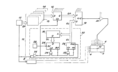
The apparatus shown in Fig. 5 comprises means 8 for
controlling the lines and means 10 for controlling the
columns. The intersection of a given line and a given column
defines an image element 12 which appears on the screen when
said line and said column are appropriately addressed.
Let us suppose. for example. m=15. whence 16 gray levels
located by the numbers 0 1 .... 15. which can be coded on 4
bits in the binary system. (For m+l gray levels. the latter
are coded on p bits. such that 2P~m+1).
The device shown in Fig. 5 also comprises means 13
provided to supply the inforrnation items concerning the gray
levels of the pixels. such information items beina coded in
the bir,ary system orl 4 ~its and dencted by GP. and the
synchroni7ation pulses. m.:re particularlv thc,se of the start
of the line.
The means 10 also comprise:
- a shift register 14 having as many positions as there
are columns in the screen each position comprising 4 bits
(if m~15).
- for each column a register 16 of 4 bits which. in the
embodiment shown in Fig. 5. is a D flip-flop of 4 bits. and a
comparator 18 and means 20 for amplifying the control signal
of the column in question. and
- means 22 which are common to all the columns and will
be described hereinafter.
~ .
- 21 - ~ 3 2~ ?J~
The information items GP are successively presented at
the input of the shift register 14 and so displaced therein
that at the start of the addressing of a line. each inform-
ation item which is associated with a pixel occupies thatposition in the shift register which i5 associated with the
column corresponding to such pixel. At the start of the
addressirl~ of the line. each information item GP is
transferred from its position in the re~ister 14 to the
inputs D of the flip-flop 16 of 4 bits associated with such
~ position. The non-inverting outputs Q of the flip-flop are
delivered to one P of the two inputs (4 bits) of the
comparator 18 of 2x4 bits. the other input Q (~ bits) of the
comparator rec~iving information items GC which are common tc~
all the controls of columns and coded on 4 bits. The
information items GC which have corne from the means 2~ corr~non
to all the columns develop increasinqly during the cc,urse of
the line time T. The output of the comparator 18 is
connected to the input of the corresponding amplificatiGn
means 20 whose output controls the corresponding column.
While the value GP is greater than the value of GC. the
output of the comparator 18 remains at the logic level O and
the column contact corresponding to the comparator 18 in
question is maintained at the potential 0 volts (activationi.
As soon as the value GC becomes equal to GP and then higher
than such value GP. the output of the comparator 18 passes to
and remains at the logic level 1. and the contact in question
.
.
.. ~. ~ ..
-. .
- 22 - 132~297
is taken to and maintained at the potential of 45 volts
(extinction).
The means 22 which are common to all the columns
comprise a first counter 24 of 8 bits adapted for reverse
counting. a second counter 26 of 4 bits, a clock 28 and a
memory 30.
The counters 24 and 26 are. for example. of the type
74193.
The means 22 also comprise a first AND gate 32 and a
second AND gate 34. The output of the gate 32 is connected
to the clock input CK of the counter 26. The output of the
gate 34 is connected to the load (inverting) input LD
("load") of the counter 24. An input of the gate 32 is
connected to the retainin~ (inverting) output RE ("carry") of
the counter 26 and the end-Gf-countina (invertina) output BO
("~orrow") of the counter 24 is connected to the c,ther input
of the gate 32 and to an input of the gate 34.
The means 13 are provided to deliver a start-of-lirle
information item to the means 8 for controlling the lines and
to the zero resetting input RA~ of the counter 26. This
start-of-line information item is also delivered to the clock
input CK ("latch") of each flip-flop 16 and to the other
input of the gate 34 via an inverter 36.
Fig. S shows that the clock input of the flip-flop 16 is
an inverter: the start-of-line pulse (logic state 1) is
inverted a first time (logic state 0) by the inverter 36.
~; ~
: ~. ;.
.,. ,. ~
~ ,, ., :-. ", . ,. :
. . ~ . . .
, - 23 _ ~32~2~7
then a second time (logic state 1) at the CK of the flip-flop
16. which is therefore charged with the information item
contained in the corresponding position of the register 14
S when the start-of-line pulse is emitte~.
The clock 28 is a regular clock of frequency 1/dt -
i.e.. N~T. The pulses supplied by the clock are delivered to
the countdown inpt DC ("down") of the counter 4.
The information items GC coded on 4 bits leave the
counter 26 and are delivered on the one hand to the input Q
of e-ach of the comparators 18 and on the other hand to the
address bus A of the memory 30 (the contents of the counter
26 therefore corresponding to an address of the memory). The
memory 3n is a memory of 15 words ~f 8 bits. The outputs Si
of the memory 30 are presented to the initialization bus of
the countel~ 24.
The c~unter ~6 is 7er~ reset at the start ,:f the line
and incremented by a signal of the end of cc~urlting down
emitted by the output BO of the counter 24, since at the end
of each countdown, the output B0 of the counter 24 passes to
the logic state 1 and. the output RE of the counter 26 being
at the logic state 1. the input ~K of the counter 26 receives
a pul-se. The counter 24 is decremented by the clock 28 and
takes into account the outputs Si of the memory 30 during the
emission of its signal of the end of counting down, since
this signal corresponds to the passage of the output B0 of
the computer 24 to the logic state 1 and. since the output of
the inverter is at the logic state 1. the input LD of the
counter 4 receives a pulse.
... . , ~
- ~
~: .
~32'~2~7
- Z4 -
The information item Si is placed at the address i of
the memory and is equal to the number of intervals dt to be
counted to pass from the number of intervals corresponding to
the gray level i to the r,umber of intervals corresponding to
the gray level i+1.
To obtain the results indicated in Table I. the contents
of the memory 30 are as follows:
10 Address0 1 2 3 4 5 6 7 8
Contents116 30 -23 20 18 17 17 16 15
__________ ________________________________________________
Address~ 10 11 12 13 14 15
Contents15 14 14 14 13 13
It can be seen in this e~:ample that the contents of the
address 15 of the memory does not matter. since it is
ignored.
The means 22 therefore operate as follows: at the start
of a line the counter 26 is zero reset. Its contents are
then 0. At the address 0, the memory 30 comprises the number
of intervals dt corresponding to the gray level 1. This
number is transferred to the courlter 24. which is decremented
by the clock 28 of frequency 1/dt. When the counter. 24 is at
zero. it delivers a pulse to the counter 26 which is
incremented as a result of the pulse. The new contents of
the counter 26 are then 1. At the address 1, the memory 30
comprises the supplementary number of intervals to be counted
:,, : . :
;.~ ~ : ; :
" .,- ~,: ,,. ,:- .: ~ ~ -:
-- .,: : . .
' - 25 - 132~2~7
to reach the number of intervals corresponding to the gray
level 2. This supplementary number is transferred to the
counter 24 ... and so on.
When the contents of the counter 26 reaches their
maximum value (15). its output RE passes to the logic state
0, something which blocks it. ~ fresh cycle starts with a
-fresh line.
The memory 30 is. for example. of the PROM type. To
perform the gray level regulations mentioned herein~efore,
something which implies modifications of the content of the
rnemory, it is enough to replace the memory by a device known
as a "PROM emulator". all other things being equal. and. once
the controls have been completed. to replace the emulator by
the memory 30. into which the values obtained by the emulator
are written. Moreover if these controls require a variation
of the number N. it is enough for this purpose to change the
clock 28.
Fig. 6 shows diagrammatically a second particular
embodiment of the apparatus according to the invention which
enables the screen 22 to be controlled with line
differentiation. The apparatus diagrarnmatically illustrated
in Fig. 6 differs from the device illustrated in Fig. 5 in
that it also cornprises a third counter 38 whose
incrementation is controlled by start-of-line pulses (which
are delivered to the clock input CK of the counter 38) and
whose zero resetting RAZ is controlled by a start-of-image
signal DI which is supplied by the means 13. The output
,
.. .,, , ~ ~ ,
. ~.- :. , -
, . - . : .
~ ~ ;, . .
: . - .
- 26 _ ~32 ~2~
number s of the counter 38 is such that 2s is at least equal
to L (number of lines on the screen). Also in the appar~tus
illustrated in Fig. 6 the memory 30 is replaced by a memory
31 of n words of 8 bits. n being at least equal to the
product of the number of lines on the screen by the nu~lber m,
equal to 15 in the example given.
The words presented on the addre--s bus A of the memory
31 comprise a part of low weight and a part of high weight.
The outputs SL of the counter 38 form the part of high weight
of each of-these words. whose part of low weight is the word
supplied at the output by the counter 26. T~e addresses of
the memory are therefore located by words of s+4 bits.
The app~ratus as described with reference to Figs. 5 and
6 mi~ht be used by an engineer in the art for controlling a
liquid crystal matrix screen.
Moreover. the present invention app]ies to the control
of both a black and white and a colour screell.
~ .
- , . . . . ..
t, , ~ , , . ., ., . ~ ,. ~ :
'' , .'.' ,' ' . .", . ~
' - 27 - 132~2~7
TABLE 1
~ _ ~ .~
1 i Nil Ii~I15 (?6) Ii/I15 (~) I
Invention Inven~iorl Pric.r art
_ . _
, O I O I , O O
10 1 1 116 1 6.7 0.1
2 146. 1 13.3 1 1
3 l 169 20.0 2.5
4 , 189 ~, 26.7 6.4
' 207 33.4 15.8
15 6 224 40.2 19.8
7 ,41 47.2 27.4
8 257 54.3 ~1.1
~ 272 60.9 45.4
i 287 67.8 54.0
2011 301 74.2 68.9
12 315 1 80.7 73.2
13 l~ 329 l 87.5 81.7
14 ' 342 93,7 95.7
, 355 100 100
. I
: ' : .