Note: Descriptions are shown in the official language in which they were submitted.
1325318 :;:
APPARATUS FOR PRODUCING A NONWOVEN FABRIC FROM `
CONT~NUOUS FILAMENTS, AND FABRIC PRODUCED THEREBY
The invention relates to an apparatus for producing a
nonwoven fabric from continuous filaments as well as to a
multiple-ply nonwoven fabric produced from continuous
filaments.
~.
Apparatus for producing a nonwoven fabric from continuous
filaments is already known from German Patent 17 85 158 and
British Patents 1,282,176 and 1,297,582. In such apparatus, a tow
o,~ filament~ i8 drawn from a liquefied composition from spinnerets ~-
with the aid of a gaseous propellant, and the individual filaments
are laid down on an apron, in the form of a belt, to form the
nonwoven.
A significant characteristic in terms of the quality of - -
nonwovens is their uniformity and strength; the strength, defined
as the ratios of the strengths in the longitudinal direction and
in the transverse direction, is determined substantially by the
angle at which the individual filaments are laid down - that is,
the delivery direction with respect to the production direction.
It is already conventional to use spinning beams with a
~ultiplicity of individual draw-off tubes for the filaments, with
one separator associated with each draw-off tube. The task of the
separator i8 to separate the filaments from the propellant air and
at the same time to spread apart the filament bundle. This
spreading at the same time defines the delivery angle.
When separators are used, allowance must be made in
- .
~'.: .. .
1325318
practice for the fact that the various separators have a major
influence on one another, because of the emerging propellant air.
Accordingly, there is only one favorable setting for the
separators, and it can be selected only once, and thus necessarily
defines the delivery direction. Hence only a very limited
opportunity exists for attaining different delivery angles.
If a slight change in the angular position of the various
separators should in fact be desirable, in order to enable
different delivery angles, then the entire apparatus must first be
shut off, because changes of this kind cannot be done during
ongoing operation of a system. Moreover, changing the delivery
angle is associated with considerable amounts of rejection in the
nonwoven fabric produced.
It has also already been proposed to provide two spinning
beams, with separators spaced apart from one another in the
production direction, and with each spinning beam having its own
delivery direction for the filaments. The result is so-called
crosswise delivery, with two respectively predetermined delivery
angles.
As noted above, the various separators affect one another
because of the emerging propellant air, so that work can only be
done with one favorable setting of the separators that is to be
selected once, so that the delivery direction is necessarily
predetermined. Thus in this version having two spinning beams,
still only limited delivery directions in crosswise delivery can
be attained. Moreover, to change the delivery angle, the entire
apparatus must first be shut off, with the attendant disadvantages
already mentioned.
A need exists in the industry for different strengths in
different directions, depending on the intended use of the
nonwoven, and this need cannot be met with the previously proposed
version having two spinning beams. -
-2-
i3253~8
In another apparatus for producing a nonwoven fabric from
continuous filaments, the so-called curtain method has also
already been used. This method dispenses with the many draw-off
tubes mentioned above; nor is any spreader (separators) used. The
tow, which forms a curtain of large surface area, extends at right
angles to the production direction; that is, the preferential
delivery direction is parallel to the production direction.
Because of the speed of the filaments, which here is higher
in every case relative to the speed of the delivery belt, the
delivered filaments move in a serpentine or wavy pattern. In
certain regions, individual filaments come to be stacked one on
the other.
Although a nonwoven fabric produced with such an apparatus
does have a preferred strength in the longitudinal direction, that
is, in the production direction, its strength in the transverse
direction is extremely poor.
The object of the invention is to devise an apparatus which
permits the production of a nonwoven fabric of high uniformity,
and which makes it possible to attain predetermined strength and -
stretching values of the nonwoven fabric in desired directions.
In the apparatus defined by the preamble to claim 1, this object
is attained by the invention by means of the characteristics of
the body of claim 1.
Because of the adjustability of at least one spinning beam,
the delivery angle can be adjusted to arbitrary values, and a
particular advantage is that such an adjustment can be done during
ongoing operation of the apparatus.
Delivery angles between 0- and 45-, and vice versa, that
is, from 0- to -45-, are preferred, so that the delivery
-3-
'' '' ,, ' ' ' ' ' , ' ' , ' '' '' ' . ., ',,'. '' '' ."' '" ' i',' .'i ',- ' i.~'. .. ;', '~ '.' . .
-
132~318
directions of the filaments of the first spinning beam and of the
second spinning beam form an angle with one another of less than
or equal to 90, resulting in a variable crosswise delivery.
A nonwoven fabric produced with the apparatus according to
the invention may have both isotropic properties and preferential
longitudinal strength. Preferential transverse strength is also
possible, without impairing the uniformity of the nonwoven fabric,
depending on the selection of the delivery angle.
The invention is also intended to produce a multiple-ply
nonwoven fabric produced from continuous filaments, which has
selectable strength values and high uniformity. This object is
attained by the invention with the characteris~ics of claim 7.
Suitable embodiments and advantageous and further
features of the invention are disclosed in the dependent
claims and in the ensuing description, as well as being shown in
the drawings.
The invention will now be described in further detail
in terms of the exemplary embodiments shown in the drawings:
Fig. 1 is a schematic side view of an apparatus having two
spinning beams; - ~-
Fig. 2 is a plan view on the apparatus of Fig. 1;
Figs. 3-5 show various delivery angles;
Fig. 6 is a more-detailed plan view on a spinning beam; and
Fig. 7 is a perspective view of a spinning beam of Fig. 6.
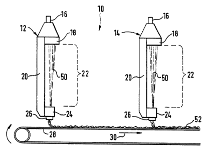
Fig. 1 shows a spinning station, identified overall by
reference numeral 10, which includes two spinning beams 12 and 14 ~-disposed spaced apart from one another in the transport direction
',
-
1 ~253~8
(production direction) 30. A liquefied spinning composition is
carried to the spinning plates 18 via liquefied-composition lines
16.
Each spinning plate 18 serves to distribute the liquefied
composition over the production width, that is, the width of an
apron or delivery belt 28. The spinning plates 18 are attached
interchangeably in the lowermost part of the spinning beams 12,
14. A variable number of holes, known as spinnerets, are provided
in the spinning plate 18, and through them the liquid spinning
composition emerges from the spinning plate 18 in the form of a
tow 50 in the manner of a curtain. The tow 50 moves along a
blower wall 20, which forms a stretching zone 20 for stretching
the tow.
The spinning station 10 also includes one filament draw-off
device 24 and one delivery apparatus 26 for each of the two
spinning beams 12, 14, by meanS of which devices the ~ilaments are
spread apart to attain high uniformity and laid down on the
delivery belt 28, which is moved in the transport direction 30, to
form a nonwoven fabric 52.
The curtain method used here accordingly operates with a
spreader - comparable to the known separators - to attain a
predetermined delivery direction of the filaments, namely a 90
direction with respect to the spinning beam. The filaments are
acoordingly moved oscillatingly back and forth up to 90- with
respect to the spinning beam. -~
-~ As Fig. 1 shows, the delivery takes place,first at the
spinning beam 12, and onto the thus-formed first layer, a second
layer is laid down at the other spinning beam 14, resulting in the
production of a multiple-ply nonwoven fabric 52.
From the plan view of Fig. 2, it can be seen that the
spinning beams 12, 14 are pivotable out of their position shown in
dashed lines, extending parallel to one another, in the direction
~ ~ ''' '
: :
1325318
of the arrows 56 and 53 about their pivot shafts 34; the
longitudinal axes 32 of the spinning beams 12, 14 here form an
angle 54. The individual plies of the nonwoven 52 accordingly
have the different delivery directions or angles predetermined by
the spinning beams 12 and 14. These different delivery directions
are shown in Figs. 3-5. Fig. 3 shows the delivery course 36 of
the one spinning beam 12, while Fig. 4 shows the delivery course
38 of the other spinning beam 14. The resultant delivery pattern
40 in the multiple-ply nonwoven 53, which is produced by the
superposition of the delivery courses 36 and 38, is shown in Fig.
5. As can be seen there, the individual delivery courses
intersect, so that the overall result for the multiple-ply
nonwoven is a crosswise delivery with variable angles. When the
intersecting delivery courses 36 and 38 in the delivery pattern 40
form an angle of 90- at the intersections, the result is an
isotropic nonwoven 52 with identical strength values in all
directions~
Part of the structure of a spinning station 10 is shown in
further detail in Fig. 6, which shows the spinning beam 12 in a
plan view. Like the spinning beam 14, the spinning beam 12 is
disposed on a rotary frame 42 and is retained and guided by means
of the guide rollers 46 along circular guide rails 44. The guide - ~
rails 44 enable a rotation of the spinning beam 12 about the ~ ;
central pivot shaft 34, so that different rotational angles 48 can
be attained. By suitably orienting the two spinning beams 12 and
14, it i8 accordingly possible to attain different delivery
courses 36 and 38 (see Figs. 3 and 4). This makes it possible for
the nonwoven 52 that is produced to be provided with the strength
values appropriate for its later use.
Guidance and retention of the spinning beam 12 on the guide
rails 44 is also shown in detail in the perspective view of Fig. -
~
7, and it should be stressed that it is also possible to set ~ :
' '. - ,
.,`
.- '. -. ' ':
' ': '; ," ' . ' . ' . . . . . , ' . , ' , ' ' .: . ' ,
1325318
different rotational angles ~8 during ongoing operation of the
entire spinning station 10. This is a considerable advantage in
the industry, because then it becomes unnecessary to shut off the
spinning station and keep it shut down for the setting of new
desired rotational angles 48 and thus for generating new delivery
patterns 40.
In summary, the spinning station 10 can accordingly be
operated in variable fashion, because during ongoing operation of
the spinning station a crosswise delivery with variable angles can
be attained. Accordingly, a desired new nonwoven product can be
produced immediately, during ongoing operation.
-7- ~ .