Note: Descriptions are shown in the official language in which they were submitted.
1 325345
~echanical Transduce~
~his lnventLon relates to a mechanical t~ansducer
wh ich cesponds ~o a forc~ which is applled to it in on¢
di~ection to exert a 0rc2 of a dlfferent magnitude in another
d~ rect~on.
It l~ a co~mon requi~ement to control a large
force by means of a small ~orce, ~or example a motor car ls
brouqht to rest uslng a re~ati~e1y light ~orce applied to a foot
brake pedal. It is also a co~mon requlcement ~o t~ke a weak
signal and generate sufficient ~orce to operate signalling
de~ices, fo~ example a vane in an alr duct can ~ense ve~y
sli~ht ai~ movement~ yet because o~ its size ie can exert a
suf~icient ~orce to ope~ate a control switch e.g. in boile~s and
ai~ conditioning apparatu~. However, the necessary control in
tbese examples ~equireR amplifyin5~ systeln~ of considerable size
15 and complexity or, in the case of the air valYe~ le~d to
possible disturbances fro~ vibratlon, overshoot or undershoot o~
tl~e delay lf ~lgnificantly damped. I~ pistons and 9i~i lar
devices a~e used as bu~fe~s, dampe~s or act~ator3, the force-to-
thrust rat}o is dcte:mined by the bore slze of the device: in
20 order to contain or to Senerate large forces the area, and hence
the diameter, ha~ to be lncreased unless unacceptably h~gh - -
pressures a~e used. However, the lncrea3e in bore ~ize, which
increases the sensitlvlty to lowec pressures, al~o ~esults in a
consideeable increase in the ine~tia of the axially displaceable
piston or cylinder, and thl~ can impalr the response and
reaction Oe the appara~us to exte~nal shock and vibcatlon
Eo~ces. Foc exa~ple, a pressure switch tWhich compcises an
e1ectrc switch ope~aeed by a pressure-sensitlve actuator) may
use a large clreu1ar diaphragm to generate a suff~cient force
from a low p~essure on its surface to overcome the teip force on
the switch tWhich may be a m~croswltch). Thls device h~s the
disadvantage that the plane in which the diaph~agm 1i~s {9
perpend~culàr to the axis o~ displacement needed to operate the
switch and thecefore the ~olume requi~ed fo~ the device is
' :
~ .
~'
: ~~ 2 1 325345
~ la~ge. Also the mass o~ the diaphragm and other moving partq
makes the device vulnerab~e to axial vibration and therefore to
spurious operation.
It is an ob~ect o~ this invention to prov~de a
5 mech~nical transducer which iq able to overcome the problems
noted ~bove.
In accordance with thls invention, there is
provided a mechanical tran~ducer, comprlslng a converter which
comprises a plurality of elongate flexlble elements joined
to~ether at their opposite ends and spaced at lntervals around a
longitudinal axis of the tran~ducee, the opposi~e ends of the
converter being displaceable towards and away from each other
along said axis, which displacement is accompanied by a bow~ng
o~ straightening of said element~, so tha~ an axial force
applied to said converter is conv~rted to a radial forca exerted
by ~aid elements, or a radlal force applied to saldelemen~s i~
convetted to an ax$al force.
It will be appreciated that the converter takes
the general form of a rib cage. ~n axial foece appl~ed between
~he end~ of the r~b cage may be a pushing force or a pul]ing
~oece, to cause the elements or cibs to bow radially outwards or
radially inwatds, or to straighten. The change in the volume
enclosed by the rib ea~e 18 substantially greater than the
volume displaced by the axially moving endQ of the rib cage. A
force applied to the rib~ radial~y inwaedly or outwardly,
produees a s~bstantlally a~plified axial oece at the ends of
the cib cage. This ~orce amplification $5 particularly large as
the ribs are deflected toward~ or away from their strai~ht
positlons.
Preferably the converter or rLb cage is provided
at l ts ends with me~ns for applying or delivering an axlal or
to~ional ~orce. ~he opposite end3 oE the rlb cage ~ay be
llnked, ln ordee to apply or dell~er ~he axial or torsional
force, either around the out~ide of the eib ca~e or theough the
rib cage oe both.
., ''' :.: , . , , ',~ ' -' : . . ...
A resll~ent element ma~l 3n~ ~d~s~posed around the
outs~e or within the rib cage oc integrally therewith, and may
secve ~o apply or absorb ~occes acting on the cib cage. ThLs
ee~ilient e~ement may comprise a membrane or pellicle the
S reslllence or elasticity o~ which resist~ the de~lection Oe the
ribs and so absorbs the ene~gy o~ axial fo~ces applied
externally to the rlb ca~e. The membcane may ~n5tead be non-
elastlc, or may be p1astlc and tend to ~eta~n its new shape
af~er deflection, or ~f elastic t need not exert any elastlc
force on th~ r~b caqeO
~ he ~e~brane may form a seal between the ~nslde
and outside o~ the rib cage. Fluid pressure may then be applied
to the inslde oc to the outside of the ~ib cage either to
pcoduce or to absorb an axal force applled between the ends of
the rib cage. The me~b~ane may comprise a tubulac membcane
appcopcla~ely c10sed oc sealed at ~ ts end~.
A ~top may be pcovided witbln the rib cagc oc
ou~side the rib cage, to llmit the inward or outward radial
displacement o~ the ribs and/or to limit the axial displac~ment
Oe ~he ends o~ the rib cage. In this manner, the stop~s) may
pcevent the rlbs straightening too much, oc golng b~yond
straight (i.e bowing in the opposite sense) or bowlng too much.
~ he rib cage may be ormed from one piece o~
sheet mat~rlal-or as a~one-piece mouldlng. Instead the ribs may
compeise separate ~e~bers llnked or pivoted at their ends to end
members Oe tbe rib cage.
~ he rib cage may be generally cylindrical in
shape, or o~ any other appcopr$at- cross-section le.~.
hexagonal), and ~t8 s$des may be parallel, conical, double
conical, stepped oe of any other pcofile.
If in the nocmal condition of the eib cage the
elbs are bowed out~ardly, t~e cibs may be wldec at their ~idd1es
than at theic end3 so a~ to reduce the gaps between adjacent
clbs. The individual rlbs may in geneca1 be of any appropclate
shape oe ccoss section. ~he rlbs may be const~cted 80 ~hat
.
. ~. -;
~ 4 1 325345
their own frictional or eLa~tic characteristicq modlfy or apply
foccç3 to the transducer.
An embodi~ent o~ th~ lnvention wil~ no~ be
desccibed by way of exa~ple only and with re~erence to th~
S accompanyin~ drawing~, in whlch:
FIGURE 1 i~ a long~.tudinal sect~on through a
transducer in accordance with this invention; showing the
transducer in a rest condition;
F~GURE 2 i~ a ~ectior. ~lmilar to Plgure l,
showing the transducec when rec~iving an applied pressure:
~ IGURE 3 ~s a plan view of a blank of sheet
material from which a ri4 cage of the transducec i~ for~Qd;
FIGURE 4 is a sec~ion through the r~b cage shown
in f lexed condi t~ons
lS ~ FIGURE S shows the rib cage wh~n formed from the
blank of ~ure 3, in lts unflexed condition;
F~GURE 6 show.~ the rib cage in its flexed
condition;
FIGURE ? is a section thro~gh an alternative rib
20 caqe, which ls assembled from lndivldual cib members; and
FIG~RE 8 is a section through a ri~ ca~e of
genecally con~cal shape.
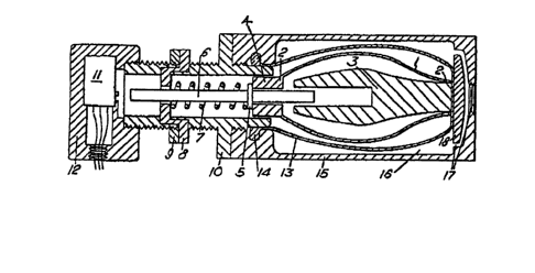
Referring to ~iguce 1 of the dcawings, there is
shown a mechanical transducer in which ~luid pressure acts
25 radially on a conveetec to produce an axial displacement oE a
push rod which actuates a ~icroswltch. The transducer
compc ises a housing lS having an internal chamber 16. l~he
converte~ 1, 2 .18 di~posed within the chamber 16 and is in ~he
~or~ oS a r1b^cage havins a plu~ality o~ elongate elements 1
30 spaced at lntervals around a longltudinal axis Oe the
transducer, the opposite ends of the e~ements oc ribs being
~oined ~ogether a~ 2, 2. One end o~ the rib cage ls flxed to or .
abuts one end 18 of the housing, whllst the other end of the rib
cage i~ ~ormed as a tbrust washer 4 recelvlng a pus~ rod 6, a
collac S on whlch abuts the thcust washec 4. A tubu1a~ membrane
:i:
~ .
'J ' . ' . . . , ~ ' , . . . ~
or pelllcle 13 cucrounds the rib cage and has one end closed oc
sealed to the end 18 o~ the housing, and i~ sealed to the
hous~ng at its other ~nd by a peripheral beadlng 14 on the
membrane be$ng ree~ived ln a groove in an apertur~ thcough the
S other end o~ the housing. This apectu~e is threaded and
rec~lves a threaded tube 10. A houslng 12, which contain~ a
~icroswltch 11, is sc~ewed onto the o~ter end o~ the tube 10.
~he push rod 6 extends along the axis o~ the tub~ 10 and a
compression spcing 7 enclrcles the push rod 6 and act5 between
the colla~ 5 on the push rod 6 and a stop member, shown
diagrammatically at 8, to apply an axial biassing force to the
cib cage, causing it~ ribs 1 to bow radially outwardly as shown
in ~lgure 1. ~he positLon of the stop me~be~ 8 along the tube
~0 can be ad~usted to prese~ the bias ~orce of the spring 7, and
the stop member 8 can be locked in position by means o~ a lock
nut 9~ An arbor or peofiled stop 3 extends along the axis Oe
the transducer ~rom the end 18 of the housng, to limit t~e
radially-inwacds displacement of the ribs 1 of the rfb cage.
1~he housing is provi~ed a~ one end with a port and with ducts 17
leadin~ ~rom this port to the intecior of the chamber 16.
In use of the t~ansduc~r shown in Figure 1, the
port 17 is connected to receive a ~l~id medium the pressure o~
which is to be monitored. Thc pressure of this medium within
th~ chamber 16 acts eadially inwards toward7 the axLs Oe the
transducer, whilst the interior of the membrane 13 is at
atmospheric pressure. ~he presuee from the medium within the
chamber 16 acts through the membrane 13 on the rlbsl o~ the ~ib
cage to dLsplace these ~ibs radially inwards: this ~as the
e~f~ct of disp1acing the thrust washer 4 axially outwards and
displacing the push rod 6 along the axis against the bias o~ the
compression spcing 7. When th~ pressuce of the medium within
the chamber 16 reaches a predetermlned value, the push eod will
bc dLsplaced sufficien~ly, against the bias-of sp~ing ~, to
contact and depress the actuator but~on of the microsw~tch ll:
th~s contition $s shown in Figure 2, in whieh al~o the ribs 1
6 1 32 53~c)
are p~essed aga~nst th~ pcof iled surface of the stop o~ arbor 3
to limi~ ~rther rad~ally-lnward displacement of these ribs.
~en the pressure of the medium wi~hin chamber 16 fall~ again,
th~ sp~ing 7 displaces the thrust washer 4 along the axis o~ t~e
tcansducer ~n the return directLon and the ribs bcw radially
outwardly again: also, the microswitch 11 resets itself.
The ~luld pres~ure at which th~ microswitc~ is
actuated can be adjusted by ad~usting the po3it~0n Oe the stop
mcmbec 8. Further ad~ust~ent is provided for by screwing the
10 tu~e 10 relatiYe tO the housing 12 so as to ad~ust its
penetration into the housing 12.
Referring to Figures 3 to 6, the ~lb cage may be
formed from a sheet o~ resiliently ~lexi~le materlal ~hich i3
cut with a seres o~ parallel slits to provide the plurallty Oe
15 e~ongate rlbs 1 ~olned eogether at their opposite ends by
marg~n-q 2 of the sheet. ~he sheet ~s then wrapped lnto tubula~
~orm as shown in Figur~ 5. ~he r$bs ~ will bow outwa~ds, a~
shown in Figures 4 and 6, by applying an axial force to displace
~he opposite end-q of the rib cage towards each other. Whi~st
the rib cage shown in Figures 1 to 6 i8 cylindrical in its r~st
condition, it may instead be conical in shape (Figu~e 8) or Oe
any other tubular shape. Instead of being a one-piece member,
the rib cage may compcise a number of resiliently flexlble
elongate members 1 fixed at theic oppos~te ends to end members 2
(Figure 7). In all of t~hese constructions, the elongate
elements 1 may be flexible ~oc made up of links pivot~d
togethec~ but not resilient: in the example shown ln ~igures I
and 2 the sp~ng 7 biasses the rib cage to a condltion in which
its rlbs are bowed outwardly. rn an alternative construction,
the medium the p~essure o which ls to ~e monitored by b~ing
introduced into the intecior of the eubular membrane 15 so as to
urge the ribs radially outwardly ~rom the con~lgurat~on shown in
Figure 2 and produce an axial dlsplacement to actuatc a
m~croswltch: in thls case the spclng 7 may act in the opposite
di~ection or the membrane 13 may be reslllent and serve to bias
~" " ~ 5~ ~f~x~ 5 ff ~ ~ y<~.~ 5.~ -
- 7 ~ 3?5345
th~ ribs l radially inwa~dly. It wlll be a~preciated that thc
transducQr may be uised as a fluid pump i~ an axlal d~lvc 1i3
applied be~ween the ends of the rib cage.
Preerably in the transducer ac~ord$ng to the
$nventlon, the ribi~ ace fllmsy and not themselves indivldualty
able to ~ithstand the stresses to wh~ch they would be subiected
i~ the membrane were absent. However, ~he membrane twhethec
provlded o~tside o~ within or integrally with the cibs~ ensureis
a stable support and distributed loading of the rib~.
In accordance with ~ucther features Oe the
invention, the membrane 13 may be permeable or apertured to
allow fluid flow between the ineerioc and exterlor ~olumes of
the r ib Cage at a predeters~ined ~ate.
Pre~erably the stop 3 prevents the e ibs I ~com
completely strai~htenlng Out, so that the ribs 1 always follow
a ~inusu~ly curved or ~lexed prof ile.
The r1b c~ge may include at least one furthec set
o~ ribs spaced apart around the axl~ of the device and
concentric with the set of rlbs 1 which are shown.
In the or each set of rlbs, the rlbs need not be
equally spaced fro~ each other nor equally ~paced from tbe axls.
The rib cage need not extent for a f~ll 360 around the ax~s.
~ he or each rib cage can be divided into two or
moce groups o~ ribs, able to displace independently of each
other. Particularly in this case, a tors~onal force may be
apptied to one end of the rlb cage ~turning about an axii3
intersectlng t~e longitudLnal axls at rlght angles), so that
ribs to one side of the longitudinal axis are bowed fucther and
the ribs to the other side of the longitudinal axis are bowed
less. Alternatively, differentlal radial forces may be applied
to the cibs tO dellver a tocsional force at the end or ends o~
the rib cage.
Whilst the transd~cer which is shown has been
de~cribed as operating an el~ct~ic switcb, it may operate any
other form of sensor, or it may operate a control device (e.g. a
~ I 325345
valve oc cla~p~.
.
~ ~ . ... . .
~, ; . -.
~ ~ , . . .
~ . . .. .
~' .