Language selection

Search

Patent 1325411 Summary

Third-party information liability

Some of the information on this Web page has been provided by external sources. The Government of Canada is not responsible for the accuracy, reliability or currency of the information supplied by external sources. Users wishing to rely upon this information should consult directly with the source of the information. Content provided by external sources is not subject to official languages, privacy and accessibility requirements.

Claims and Abstract availability

Any discrepancies in the text and image of the Claims and Abstract are due to differing posting times. Text of the Claims and Abstract are posted:

  • At the time the application is open to public inspection;
  • At the time of issue of the patent (grant).
(12) Patent: (11) CA 1325411
(21) Application Number: 603398
(54) English Title: SHIPPING AND STORAGE CONTAINER FOR SYRINGES
(54) French Title: RECIPIENT POUR LE TRANSPORT ET LE STOCKAGE DE SERINGUES
Status: Deemed expired
Bibliographic Data
(52) Canadian Patent Classification (CPC):
  • 217/146
  • 217/192
(51) International Patent Classification (IPC):
  • B65D 81/02 (2006.01)
  • B65D 43/02 (2006.01)
(72) Inventors :
  • PAYNE, JOHN B. (United States of America)
  • JONES, DAVID R. (United States of America)
(73) Owners :
  • MILES INC. (United States of America)
(71) Applicants :
(74) Agent: FETHERSTONHAUGH & CO.
(74) Associate agent:
(45) Issued: 1993-12-21
(22) Filed Date: 1989-06-20
Availability of licence: N/A
(25) Language of filing: English

Patent Cooperation Treaty (PCT): No

(30) Application Priority Data:
Application No. Country/Territory Date
212,683 United States of America 1988-06-20

Abstracts

English Abstract


ABSTRACT OF THE INVENTION
The container of the present invention for storing and
shipping syringes comprises a base with a plurality of
ports, each adapted to receive a syringe, and a cover which
fits over the syringes and locks onto the base. The base is
made of insulative material so as to protect the medicinal
fluid within the syringes from temperature extremes. The
cover is transparent for easy identification of the con-
tents. The sidewalls of the cover are corrugated to provide
strength to the cover. The top of the cover and the bottom
of the base are flat so that a plurality of containers can
be stacked one upon another for shipping and storage.


Claims

Note: Claims are shown in the official language in which they were submitted.


The embodiments of the invention in which an exclusive
property or privilege is claimed are defined as follows:
1.
A container for storing and shipping syringes, each
syringe including a barrel for holding fluid to he injected,
a needle attachable to the barrel, and a plunger for eject-
ing the fluid from the barrel and through the needle, the
container comprising;
a base having a top, a bottom, and interconnected sidewalls;
and having a plurality of ports extending downwardly
from the top, each port being adapted to receive a
syringe;
a cover having a closed top, interconnected side walls
terminating in a lower edge, and an open bottom so as
to fit over the syringes; and
means for securing the cover to the base.
2.

The container of claim 1 wherein the means for securing
the cover to the base includes outwardly projecting lip
means on the sidewall of the base and indentation means on
the lower edge of the cover, the sidewalls of the cover
being resilient such that said indentation means can pass
over the lip means to overlapping and retentively engage the
lip means so as to hold said cover in position on said base.

-6-


3.
The container of claim 1 wherein the sidewalls of the
cover are corrugated to provide strength to the cover.
4.
The container of claim 1 wherein the cover includes lip
means for engaging the top of the base to limit downward
movement of the cover with respect to the base.

5.
The container of claim 1 wherein the base is made of
insulative material to protect fluid in the syringes from
temperature extremes.

6.
The container of claim 1 wherein the top of the cover
is flat and the bottom of the base is flat so that multiple
containers are stackable one upon another.

7.
The container of claim 1 wherein the cover sealingly
engages the base to provide an air-tight enclosure for the
syringes.

-7-


8.
The container of claim 1 wherein the ports extend
partially into the base without extending through the base.

9.
The container of claim 1 wherein the cover is trans-
parent.

10.
The container of claim 1 wherein the cover includes
dimples adjacent the lower edge to provide frictional en-
gagement with the base.
-8-

Description

Note: Descriptions are shown in the official language in which they were submitted.


~ `:

132~


~ .

o


. .
X, BACKG~OUND OF ~rHE I~VE~ON
Syrln~ often pr~-~ille~ wi~h the fluld ~o be
ln~eated prlor to ~hlpplng ~nd ~toring o~ the illed ~-
rln~e~ . Su~h pre-fil lod syringe0 mu~t be proteated frC:Ih
.1 temperature extre~ t4 ~Iv~ damagl3 to the medlcinD.l flu4d.
A1BO~ it i~ de~ir~bl~3 to prot~ct th~ p~e-~illed oyrin~es
f~om phy~lcal damag~ during ~hipping and ~ts:~r~g~.
^ii Accordlngly, ~ prlm~,ry ob~ctive o~ th~ pr~nt lnvep-
,lj~ ; tion i~ tha provi~ an lmprw~d ~hipplng And ~tc~ra~e;
aontaLn~r or ~yring~
Ano~:her obJ~a~:lve of th~ pre~ nt lnvention lg ~hqs
p~ovi~lon o~ ~ syring~ con~tllner ~qhlch pro~ec~ the fluld
wlthin ~ho ~yrLs~ r~m~ t~mpQrature ~x~en~es.
A furtbor ob~ec~i~e of th~ pr~nt irlvention i~ th~
prc:~t~on of a ~yringe cont~lner whlch allow~= for eai~y
. .
~, ~; id~n~iPiceltlon o ~h~ con~ent~. ^
till ~no~he~ o~ec~lv~ of the pre~ent ln~ ntlon ~ he
i:~ pr~ ion oP a i~hippin~ arld ~t~r~g~ ~ontaine~ for ~iyrlng~
.~ wh~ h 16 e~:onomic:al.'co 3n~nu~ture and durabl~ u6e.
; :~

^i~ SU~ARY OF Ttl~ X~N~I~N.
~ho ~y~inge ~onkaine~ o~ kh~ pro~en~ ~ n~rention ~nclu,~
: ., a bas~ having a plurality o~ ho~ eB or port~ ~x~ndi.ns~ dowp-
~ wardly t:hereln, wi~h sach port bein~ ad~pteA ~o r~c:eive ~
6yx~nge. A cov~ ~it~ ov~x the ~rring~ ~nd loek~ ~nt~ ^the
~ i


11


~32~411
"
base to provide an enclosed container. The base is made of
an insulative material, such as styrofoam, so as to protect
the syringe from temperature extremes. The cover is trans-
parent so as to allo~ easy identification of the syringes.
Also, the top and bottom of the container is flat so that
multiple containers can be stacked one on top of another.

:1 .
.,
BRIEF DESCRIPTION OF THE DRAWINGS
Figure 1 is a perspective view of the syringe container
of the present invention.
i Figure 2 is a side elevational view of the container.
. ,1
, Figure 3 is an end elevational view of the container.

l~ Figure 4 is a top plane view o the container.

-, Figure 5 is a sectional view taken along lines 5-5 of
.,
i, Figures ~.
Figurs 6 is an enlarged partial ~ectional view taken
along lines 6-6 of Figure 4.


DETAILED DESCRIPTION OF THE DRAWINGS
The syringe container of the present invention is
generally designated by the reference numeral 10 in the
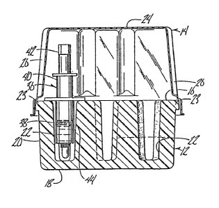
drawings. Contalner 10 includes a base 12 and a cover 14.
Base 12 includes a top surface 16, a flat bottom sur-
face l~, and interconnected side walls 20. A plurality of
ports or holes 22 extend down~ardly from top surface 16 and


::i
. ~, .
-3-
,. . ~,, ,~,

'^r
."~, . . . .
.. . . . .


~' ' :' ; ' ' ' i . ' ' ' .'
: - : .' . . '
,',; , ~ ' ~ : : ~: i , . . , : . ...
; .: ~ ~ : .
.. , , ~ .
.

: 132~411
:i

terminate within base 12. Each port 22 is adapted to re-
ceive a syringe, as seen in Figure 5. Base 12 also includes
~i n outwardly pro~ecting lip 23 which extends around the
sidewalls 20 ad~acent top 16.
.l Cover 14 includes a flat top 24 and interconnected
i. ~idewalls 26. The bottom of the cover ij open 80 that the
:~i
cover can fit over the syringes, as seen in Figure S.
Sidewalls 26 are corrugated so as to provide strength for
the cover. Sidewalls 26 of cover 14 terminate in an out-
` wardly projecting lip 28, a downwardly extending flange 30,
~ and an outwardly extending lower edge 32, as seen in Figure
.l 6.
:, Lip 28 of cover 14 provides a stop surface for engaging
l the top surface 16 of base 12 and thereby limiting downward
;l movement of cover 14 with respect to base 12. Along the
~;,
lower edge 32 of cover 14, are a plurality of indentations
. 34, at least at the corners vf the cover, which allows cover
.~ 14 to snap fit over the lip 23 of base 12, and thereby
secure the cover to the base. Dimples 35 may be provided on
.~ flange 30 of cover 14 to provide increased frictional
~l engagement wLth lip 23 of base 12. While.the drawings show
.~ lip 23 extending continuously around base 12, it is under-
stood that individual spaced apart projections could also be
;
,~ provided for overlapping engagement by the indentations 34
on cover 14.
.~
-4-
. ~ i:.,


;

.
:. : .. . , : , ::
... . . .
. ,-., : : - . . ,
.. ~ ; , . ,

' ' . ~ ! '

1325411


.


In u ~, 6y~1ng~a ~ ~r~ p~ed ~n 1;h~ ~:e~pective port¦s
22 o~ b~e 12 ~nd cov~r 14 i~ pla~ed over the ~ringe~ anl
.l ~n~p ~1~ onto ~h~ lip 23 o ba~e t2. Ao ~e~n ln l~iQU~13 5,
'! porte 22 ~lre ~u~ lGrll;ly ~p to r~ceive ~he b~rI~i31 3~ o~
~y~lnçl~ 3fi, but the port~ ~o n~t oxt6~d ~l~ar through the
ba~e. A~ ~hown in the tr~wing~, ~yring3 35 al~o $nclucl~
9 hollo~ plun~er 40 with a hou~lng 42 ~or the needl~ ~nt~t
., ~hown) being rec~lv~d within th~s plu~lge~ und~r~;toc~d
.: th~t p~J:tB 22 cRn b~ Gf ~n~ ~h~pe and con~lgurA~ion to
eceivf3 other l3tylfs~ o$ ~yrlng-3æ, ~L~hout departing ~rs: m t he
~ ~cope of ~he pr3~6}nt i}W9nt;$0n. PLçlur~3 5 al~o illu~r~te~
.1 ~yrin~a 36 ~ being pr~ d wlth a medlclnal ~uid 44,
~ Els~e~ 12 is m~de ~o~ An in~ul~tlve n~te~ uch ~
~tyro~o~m or ~he lik~, whioh pr~tects the m~dicinal ~lu~d~44
fxom temperature extr~me~ over 14 ~Qalin~ly eng~ e~
ba~6~ 12 ~ to pro~r~de an ~lr-tl~ht enolo~ure for the
7 ~ 6yringe!la . Such a$~-ti~htne~ pr~ e~ $o~ the in~ul~tic~n
i, ~o~ th~ ~luid. Pr~ar~bly, ~over 1~ ran~par~nt EiC~ ~h~Lt
,j : identifyin~ indîci~ on the ~yringe6 can be e~ily ~iew~d.
A1GO~ ~ince the bo~tom of th~ b~e an~ the t:Dp of the c~r
.id
e ~làt, ~ultipl~ contaln~ 10 oaln be ~t~cked on~ upen
'I
anoth~L ~or ~hipping ~nd ~tor~ge~.
From the ~orogoing d~s~rl~t~.~n, it c~n be ~een ~,h~t ~he
pr~ t lr~v~ntion acaompll~he~ a~ lo~t all o~ th~ ~t~
; ~b~ctiv~.

.: I

, . _5_
,
''''' .
. ~ . .. . . .

Representative Drawing
A single figure which represents the drawing illustrating the invention.
Administrative Status

For a clearer understanding of the status of the application/patent presented on this page, the site Disclaimer , as well as the definitions for Patent , Administrative Status , Maintenance Fee  and Payment History  should be consulted.

Administrative Status

Title Date
Forecasted Issue Date 1993-12-21
(22) Filed 1989-06-20
(45) Issued 1993-12-21
Deemed Expired 2002-12-23

Abandonment History

There is no abandonment history.

Payment History

Fee Type Anniversary Year Due Date Amount Paid Paid Date
Application Fee $0.00 1989-06-20
Registration of a document - section 124 $0.00 1990-06-22
Registration of a document - section 124 $0.00 1993-09-10
Maintenance Fee - Patent - Old Act 2 1995-12-21 $100.00 1995-11-24
Maintenance Fee - Patent - Old Act 3 1996-12-23 $100.00 1996-12-05
Maintenance Fee - Patent - Old Act 4 1997-12-22 $100.00 1997-12-04
Maintenance Fee - Patent - Old Act 5 1998-12-21 $150.00 1998-12-09
Maintenance Fee - Patent - Old Act 6 1999-12-21 $150.00 1999-12-02
Maintenance Fee - Patent - Old Act 7 2000-12-21 $150.00 2000-12-01
Owners on Record

Note: Records showing the ownership history in alphabetical order.

Current Owners on Record
MILES INC.
Past Owners on Record
DIAMOND SCIENTIFIC CO.
JONES, DAVID R.
PAYNE, JOHN B.
Past Owners that do not appear in the "Owners on Record" listing will appear in other documentation within the application.
Documents

To view selected files, please enter reCAPTCHA code :


To view images, click a link in the Document Description column. To download the documents, select one or more checkboxes in the first column and then click the "Download Selected in PDF format (Zip Archive)" or the "Download Selected as Single PDF" button.

List of published and non-published patent-specific documents on the CPD .

If you have any difficulty accessing content, you can call the Client Service Centre at 1-866-997-1936 or send them an e-mail at CIPO Client Service Centre.


Document
Description 
Date
(yyyy-mm-dd) 
Number of pages   Size of Image (KB) 
Drawings 1994-07-16 1 84
Claims 1994-07-16 3 86
Abstract 1994-07-16 1 31
Cover Page 1994-07-16 1 28
Description 1994-07-16 4 187
Representative Drawing 2002-01-08 1 17
PCT Correspondence 1990-04-30 3 55
Office Letter 1989-10-20 1 37
Office Letter 1989-10-24 1 61
Prosecution Correspondence 1990-05-14 1 16
Office Letter 1990-06-08 1 43
Office Letter 1990-06-08 1 44
Prosecution Correspondence 1993-09-24 1 35
Prosecution Correspondence 1992-09-24 2 48
Examiner Requisition 1992-05-27 1 56
Fees 1996-12-05 1 44
Fees 1995-11-24 1 49