Note: Descriptions are shown in the official language in which they were submitted.
132~622
PR~SSURE REGULATORS
There ls now a well-establishedi wish for aerosol dls-
penser packages which use compressed rather than llqulfied gas
1~; propellants. A fundamiental need in satisfylng this wish 19 the
provision of a regulator whereby the product to be dlspensed ls
propelled from the package at a generally constant flow rate. In
the aibsence of such regulation the dispensed flow rat0 will inl-
tlally be too great and progresslvely reduce wlth the propellant
pressure as the package emptles. Thls i5 not compatible wlth the
maintenance o~ a generally consistent spray and other discharge
characteristlcs whlch are required for most products.
Various forms of regulators have been proposed whereby,
as the gas pressure reduces, the product metering orifice is
effectively progresslvely increased in slze in order to maintain
' the flow rate. However, none o~ these proposals has proved prac-
tlcable in large scale manufacture.
An ob~ect of the present invention is to provlde an
lmproved such form of regulator and, to this end, there ls pro-
vlded a pressure regulator comprlsing: a pressure regulator
comprlslny: a chamber formlng a successive pair of compartments
at respectively opposlte ends thereof, one of sald compartments
- partly defining a restricted passageway leadlng to an outlet open-
a ing from said chamber, and the other of said compartments havlng
~j an inlet opening into said chamber; a diaphragm located across one
j end of sald chamber to close said other compartment, sald one end
belng remote from sald one compartment; a sprin~ operable to urye
sald dlaphragm to move lnto said other compartment towards sald
1 ~. . . . .
132!~22
la
outlet openlng; and a piston connected wlth said dlaphragm for
movement therewlkh and located in sald one compartment to deflne
~ therewith sald passageway, said one compartment and plston co-
.j operatlng progresslvely to lncrease the effective slze of sald
,: passageway as sald dlaphragm moves towards sa~d outlet opening,
~,
;~ sald diaphragm havlng a suspended part and ~he suspended part
~J having a larger surface area than the mutually faclng sur~ace of
,.......... the plston so that the respectlve forces actlng on the dlaphragm-
to-plston connection due to an lnput pressure actlng on the sur-
faces ln sald other compartment are substantlally equal and oppo-
site, whereby the resultant output pressure ln said one chamber
;j
which acts on the plston surface remote from the diaphragm ls
,J determined essentially by the force o~ sald sprlng.
.~
In use of the present regulator pressurlsed product
~ enters the chamber by way of the lnlet openlng and other
;'31 compartment ln
JI :
~' 1
: ~j
-
~ 32~2'~
-- 2 --
a relatlvely unrestrlcted manner and so acts on the lnner face of
the dlaphragm and the opposed lnner faee o~ the plston wlthout
any pressure reduct~on of slgn~flcance. Product leaves the
chamber by way of the one compartment and outlet openlng and so
05 add~t10nally acts on the outer face of the plston, but at a
pressure dependent on the actlon of the restrlcted passageway
through the one compartment. At the same tlme, the spr1ng acts
on the outer face of the dlaphragm.
Generally speak~ng the sum of these actlons ls that of a
balanced plston assembly because the d~aphragm can be equated
w~th a further plston of predetermlned d~ameter. The use of a
d~aphragm rather than a further plston ls, however, beneflclal ln
facllltatlng closure of the chamber wlthout the need for 0-rlngs
or equlvalent sl~dlng seal members.
15Ideally the d~aphragm equates w1th a p~ston d~ameter wh~ch
equals that effectlve for the inner face of the f~rst-mentloned
p~ston. In these clrcumstances the spr~ng force w111 act to move
the flrst plston untll the effectlve slze of the restricted
~ passagsway produces a pressure wh1ch acts on the outer face of
; 20 the plston to balance such force. In the result the regulator
operates to control the product output pressure ln dependence
i upon the spr~ng force and thls force can be malntalned
~, substantlally constant.
~i In practlce the provlslon of a dlaphragm whlch equates wlth a
plston dlameter whlch ls suff~clently constant over a range of
operatlng pressures, and resultant dlaphragm deflectlons, may not
be a stralghtforward matter. Accordlngly the dlaphragm sultably
approxlmates the relevant dlameter.
It w~ll be appreclated that the spr~ng ls located outslde the
;' 30 chamber effectlvely to act on the outer face of the dlaphragm and~ also that th~s last-mentloned face ~s not to be sub~ected
`3 dlrectly to product pressure. For these purposes the sprlng ~s
preferably slted ln a tubular member havlng one longltudlnal end
open, and the dlaphragm ls formed across one end of a sleeve of
slmllar tubular form for sealed mounting over the member one end,
I
:,
~ - ~ . ;: : . . . .
~ , ,
~ ~;
:
;~
132~62?J
- 3 -
pressure wlth1n the chamber other compartment act~ng on the
sleeve to ald lts seal~ng on the me~ber one end wlth the sprlng
.l aetlng central1y o~ the dlaphragm.
Var~ous forms can be used for the one compartment and plston
05 whereby these elements cooperate in the requ~sl~e manner.
~i The present preference ls for these elements to have
respect~ve mutually faclng annular surfaces between whlch the
restr1cted passageway ~s deflned these surfaces each belng
slmllarly ~ncllned relat~ve to the dlrectlon o~ regulator
~ovement and separat~ng 1n progress~vely lncreas1ng manner ~rom
near-seallng engagement as the plston moves towards the outlet
openlng. The annular sur~aces ln questlon are themselves
suitably mutually incl~ned at a small angle such as 3-5 to
extend dlvergently towards the outlet open~ng.
In an alternat~ve form the plston ls ~n a near-sealing
relatlonsh~p wlth~n a portlon of the one compartment such
port~on belng of cyllndr~cal form and havlng a keyway of whlch a
`~ closed end sect~on 1s progresslvely lntreaslngly exposed to the
flrst compartment as ths plston moves towards the outlet openlng.
In thls last context a near-seallng relat~onsh~p ls to be
understood as one in wh~ch fluld flow past the p~ston occurs
predom~nantly by way of the keyway but wlthout the p1ston
contact~ng the ad~acent compartment to glve r7se to fr~ctlon.
Preferably ~n appllcation to an aerosol dlspenslng package
the proposed regulator ls located downstream of an operatlng
valve relat~ve to the product ln the package whlch valve ls
operable to open and shut the package lnterlor for the purposes
~ of product release or not. In thls event the regulator ls
-¦ pre~erably of a form ~n whlch the plston cooperates wlth a probe-~ 30 to close the outlet openlng when the operatlng valve ls shut.
The probe for thls purpose can be connected wlth the p~ston ~or
movement therewlth. AlternatlYely a separate sprung probe can be
used the sprlng act~on o~ such probe be~ng normally effect~ve ~o
open the orlflce and the probe being operable agalnst lts spr~ng
3~ b1as to close the outlet openlng by plston movement to engage the
probe.
'.
'~" ` . ' ~,
132~22
,
Also, when the proposed regulator ls located downstream of an
assoclated operat1ng valve, an addltlonal valve ls preferably
- connected between the operatlng valve and lts operatlng button or
other actuator to reduce the loss of propellant wh~ch may
05 otherwlse occur wlth operatlon of the package when t~lted
substantlally from an ~prlght dlspos~tlon.
Such an add~tlonal valve compr~ses a chamber havlng lnlet and
outlet openlngs, and a ball housed ln the chamber for movement
towards and away from the outlet open1ng, the outlet openlng
belng outwardly convergently tapered for substantlal seallng
;engagement of the ball thereln, and the chamber be1ng def7ned by
two parts sealably sl1dably ln~erconnected for llmlted mutual
telescop~ng movement.
In the presently proposed use, the lnlet and outlet open~ngs
of the addltlonal valve are respectlve1y communlcated w1th the
operat~ng valve outlet and the regulator ~nlet. If the package
ls rotated substantlally from an uprlght dlsposltlon, actuatlon
of the operat1ng valve does not cause d~spenslng because the
propellant pressure and modlfled grav~tatlonal actlon on the ball
are such as to move the ball lnto sealed engagement 1n the
, tapered geometry of the openlng. Any tendency for the ball to
,~ stlck 1n the tapered open~ng ls allevlated by the fact that
actuatlon of the operatlng valve wlll act to compact
telescoplcally the chamber of the addltlonal valve and,
correspondlngly, when the operatlng valve ls released, propellant
pressure ln the chamber ls relleved by causlng telescoplc
expanslon. If necessary, further pressure reductlon and,
posslbly, back-flow may be caused by manually llftlng the
operatlng button to the extreme of lts limlts. The ball can then
1 30 fall from the tapered openlng on returnlng the package towards an
upr~ght dlsposltlon, or such ball movement can be eaused by
shaklng the d~spenser.
Examples of ~he above forms of the ~nventlon are descrlbed
below, whcreby these and other forms can be be$ter understood and
appreclated, wlth reference to the accompany~ng drawlngs, ln
whlch:-
.
, . - , ,
': ~ ; ., ~
~32~2~
- 5 -
Flgure 1 schemat~cally lllustrates one form of a regulator
accordlng to the ~nventlon, whlch regulator ls provlded wlth an
outlet closure probe and a t~lt protectlon valve,
Flgure 2 s~m~larly lllustrates a ~od~flcatlon of the
05 regulator of Flgure 1,
F~gure 3 lllustrates ln sim~lar manner an alternatlve form of
probe from that of F~gure 1, and
Flgures 4 and 5 lllustrate one embod~ent of the form of
Figure 1 respectlvely in cross-sect~onal v1ew when assembled and
partlally sectloned exploded vlew.
Flgure 1 shows the upper port~on of an operatlng button 10
for an aerosol d~spenser package. Thls button ~s sultably
operable by depresslon relative to the package to open a
normally-closed valve communlcated by way of a dlp tube wlth a
lS fluent product packed ~n a can or other vessel under gas
pressure. De~all of the valve, dlp tube, can, product and gas ls
not necessary to an understandlng of the regulator of Figure 1
and lts operat~on, except to note that the gas pressure wlll
reduce as descr~bed ~n ~he ~ntroductory passage above and that,
ln use, product to be d~spensed ls applled under gas pressure to
the regulator by way of passageway 11 ~n the button.
The regulator of Flgure ~ ls denoted generally at 20 and ~s
housed ln a transverse dlametral bore 12 in the button.
The regulator has a maln body 21 f~tted ln the bore 12 to
extend partway therethrough from one end. Thls body ls axlally
hollowed from lts other end to deflne a chamber 22 formed by
~lrst and second compartments 23 and 24 leadlng success~vely to
an outlet openlng 25 formed by the orlflce of a spray nozzle 30
at the one end of the body. At lts other end the rad~ally outer
surface of the body is clrcumferentlally relleved to form an
annular channel 26 bet~een ltself and the button, thls channel
communlcates ~th the passageway 11, and the body at the floor of
the channel ls formed wlth apertures 27 at lntervals therearound
addlt~onally to commun~cate the channel w7th the f~rst
compartment of the chamber.
'': . ' : ~ -
- 132~22
- 6 -
; A regulator control member 40 ls located ln the chamber.
Thls member comprlses a dlaphragm 41 dlsposed transversely across
the flrst compartment the dtaphragm havlng a plstcn rod 42
pro~ectlng from lts centre towards the second compartment and a
05 tubular flange 43 pro~ectlng from lts perlphery ln the opposlte
i dlrectlon. At lts end remote ~rom the dlaphragm the piston rod
carrles a plston 44 sited 1n the second compartment and from the
p~ston centre a probe 45 pro~ects towards the outlet open7ng.
The plston and a long~tudlnal port~on of the second compartment
are formed wlth respect1ve mutually fac1ng annular surfaces 46
and 28 whlch are slmllarly lncllned ln dlvergent manner towards
the outlet openlng. Preferably these surfaces are mutually
lncllned at a small angle of 3-5 ~n d~vergent manner towards the
outlet and deflne therebetween a restrlcted passageway 29 of
l~ 15 variable slze dependent on the poslt10n of ~he plston ln the
second compartment.
The control member ls held ln posltlon by a closure member 50
for the chamber. Thls closure member ls of capped plug form
havlng an end part 51 to close the chamber and a tubular part 52
- 20 extendlng wlthln the body to serve as a mount for the dlaphragm
flange 43.
A compresslon sprlng 60 ls located to act between the closure
member end part and the control member dlaphragm the end part
and dlaphragm belng sultably formed wlth respectl~e proJectlons
53 and 48 to seat the ends of the sprlng.
Operatlon of thls regulator ts essent~ally as descrlbed
above. Depresslon o~ the button lO opens the assoclated valve to
allow flow of product from wlthln the can under gas pressure
1nto passageway ll lnto the annular channel ~6 and through the
1 30 apertures 27 lnto the chamber 22 where regulation occurs.
It wlll be noted that release of the button closes the
; associated valve and supply of pressurtsed product to the
chamber 22 ceases. In these clrcu~stances the control member 40
ls urged by the sprlng 60 to close the outlet openlng by
engagement of the probe 45 wlth the latter. Thls ls beneflclal
: 1n malntalnlng the open~ng free of blockage by drled product.
.. ..
,. ~ .
?.`: `: . : `
` o
. 132~622
-- 7 --
Lastly ln Flgure 1 an lncllnatlon protect~on valve ls
assoclated wlth tlle regulator and denoted generally at 70.
. The valve 70 ~ncludes a chamber 71 formed by two parts 72 73
each of generally tubular form and ~nterconnected for sealed
05 llmlted mutual telescoplng movement. Part 72 ls connected wlth
the button 10 and defines for the chamber 71 a convergently
tapered outlet openlng 74 communlcated wlth passageway 11 of the
button. Part 73 w~ll be connected wlth the operating valve and
deflnes an lnlet openlng 75 for the chamber wh~ch wlll be
commun~cated wlth the outlet of such valve. Part 73 also
~ncludes an apertured transverse member 76 located across lts
lnter~or to render captlve wlthln the chamber a ball 77 of
dlameter greater than the mlnlmum for tapered outlet openlng 75.
In use of the relevant dlspenser actuatlon of the button
wlll open the operatlng valve and at the same tlme
telescop7cally compact the parts 72 and 73. If ln thls
s1tuatlon the package is suff~clently rotated from an upr~ght
dlsposltlon as to render d~spens1ng act~on undeslrable because of
a consequent loss of propellant the ball w~ll move to close the
protectlon valve as descr~bed earl~er above. Thereafter when
the ~neffectlve operat~on ls appreclated and the button released
the operat1ng valve is closed and the propellant pressure
otherwlse retalned between thls last valve and the ball ls
reduced by actlon of th~s pressure to telescop~cally expand the
parts 72 and 73. Thls pressure reductlon facllltates release of
the ball from the tapered open~ng agaln as descrlbed above.
In the mod~f~catlon of F~gure 2 the p~ston perlpheral
surface 46~ ls close to a seallng relat~onsh~p wlth a cyllndrlcal
surface portlon 28~ ~n the second compartment except for a
keyway 29a formed axlally ln such surface port~on. Thls keyway
forms a restrlcted passageway of progresslvely lncreaslng
effectlve slze as the plston moves towards the outlet openlng to
expose mor~ of the closed end portlon of the keyway to the flrst
compartment.
i 1325622
i - 8 -
In the mod1f1cat10n of F19ure 3 an alternat1ve form of
probe 45b ls shown. In th~s alternatlve the probe is of sprung
form mounted dlrectly wlth~n the regulator body 21k rather than
on an assoclated plston. The spr~ng actlon of the probe ls such
OS that the ad~acent outlet openlng 25b ls normally open, but the
openlng is c10sed by plston movement to engage the probe and urge
the latter aga7nst lts spr~ng blas towards the openlng.
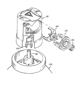
In the embodlment of Flgures 4 and 5 the parts are deslgnated
by the same reference numerals as those o~ F~gure l for
correspondlng ports, but with the add1t10n of a one hundred dlg1t
for purposes of d~stinct10n. Much of the nature of th1s
embodlment and ~ts operatlon accords wlth the preced1ng
descriptlon of Flgure l, but some dlst~nctlve features of
practical s~gnlf~cance arlse and 1t 1s use~ul to note these.
A group of such ~eatures ~nvolve manufacture of parts for
push-f~t and snap-flt 1nterconnectlon to ~acllltate assembly.
For example, the tubular part 152 ~s formed w~th the button llO
and rece1ves the dlaphragm flange 143 ln a seallng push-flt. The
dlaphragm ls, ln turn, formed separately from the p~ston 144 and
these parts are connected by snap-f1t of the p~ston rod through
the d1aphragm centre. Also the p1ston engages 1n the body part
120 by snapp1ng the ~ncl~ned annular surface of the former past
the relat1vely ~ncllned s1m~1ar surface of the latter. Aga1n,
the body part ls engaged ln the button with a rlb-and-groove
snap-f~t formatlon, whlle the spray nozzle ls a push-flt ln the
body 120. Lastly, the t11t protectlon valve sl1d1ng part 173 ls
connected wlth lts related part 172 by way of a snap-f~t.
The two-part construct~on o~ the control member 130 from
plston and d~aphragm parts represents another feature of
slgnlficance. Th~s construct~on facllltates the prov~s~on of the
qu1te different physlcal propertles approprlate to the
const1tuent parts by allow~ng the use of eorrespond~ngly
I dlfferent mater1als.
I Another ~eature 1nvolves the prov1s10n of a vent 154 to
atmosphere from the space beh1nd the dlaphragm to avo1d varlat10n
of pressure ~n th~s space 1n assoc~at~on wlth d~aphragm movement.
:
.. ,. , .. ~ - . :
~32~22
~ 9
Also ~t ls to be noted as seen from F~gure 5 that the
slldlng part 173 ls formed for d~rect engagement wlth the tubular
outlet openlng 181, or so-called stem, of the operatlng valve
pro~ect1ng from the can 190 of the package part1ally shown 1n
05 thls f~gure. The operat1ng valve can, of course be o~ any
su1table form and to the extent that there are a var1ety of
well-establ~shed commerclally-avallable op0ratlng valves w~th
d~f~erlng s1zes of stem lt may be approprlate to make the
proposed regulator wlth a correspondlng var1atlon o~ slldlng
parts 173. Alternatively the slldlng part 173 may be
standard~sed for use w~th vary~ng adaptors for connectlon wlth
dfferent operatlng valve stems.
Hhlle the ~nventlon has been descrlbed wlth more part1cular
reference to the lllustrated forms and embodlment ~urther
modif1cat7On and varlatlon ~s poss~ble w1thln the 1nventlon as
presented more broadly ~n the precedlng lntroductory passages.
It ls also appropr1ate to note that some features of the
lnvent~on as descr1bed above are not necessarlly related to the
proposed regulator. Thls ls true of both the probe and
lncl~nat~on protect~sn valve. The probe ls equally appllcable
for example to other regulators simllar to that above ln
comprlslng a control element rec1procable w~thln and along a
flu1d path to regulate the same ln response to propellant
pressure varlat~ons and a b~as sprlng wlth the spr~ng urglng the
element towards an outlet orlflce for the path. The protectlon
valve ~s slm~larly appl~cable to other regulators and ~ndeed
other aerosol d1spenser package sltuatlons where propellant loss
by operatlon in lncl~ned attltudes ls to be avolded.
Lastly whlle the proposed regulator has been concelved and
developed to date for appllcatlon to aerosol dlspenser package
other appl~catlons are poss1ble 1n relat~on to slmllar regulatlon
requ1rements ln d~fferent con~exts.