Note: Descriptions are shown in the official language in which they were submitted.
1 325954
This invention relates to a cleaning device of the type
adapted to entrain a cleaning material such as metal
particles, ceramic particles or sand in a pressure fluid
stream and impinge it against a surface to be c]eaned.
Cleaning devices of the type adapted to impinge a
pressure fluid stream containing a cleaning mate!rial such as
metal particles, ceramic particles or sand against a surface
to be cleaned through a nozzle flow passage disposed in a
cleaning head have been in widespread use for cleaning the
surface of a large-sized structure such as an oil reservoir
tank, a tall building and a ship. Usually, this type of
cleaning device includes a closing member defining a
pressure-reduction space in cooperation-with the surface to
be cleaned. The cleaning head is mounted on the closing
member, and the tip of the nozzle flow passage is positioned
within the pressure-reduction space. A suction means is also
provided which draws the fluid from the pressure-reduction
space through an outflow passage. By the action of the
suction means, the pressure-reduction space is kept in a
pressure-reduced condition, and the closing member having the
cleaning head mounted thereon is vacuum-attracted to the
surface to be cleaned. The cleaning material impinged against
the surface from the nozzle flow passage is entrained in a
fluid stream sucked from the pressure-reduced space through
the outflow passage, and recovered from the pressure-reduced
space. The specification, claims and drawings of U. S. Patent
No. 4,095,378 (Japanese Patent Publication No. 26752/1985)
may be cited as a typical example of the prior art disclosing -~-
conventional cleaning devices.
-- 1 --
-., . - ~ :. ~ - .. . . .- .. , .,, . - . . :
595~ :
The cleaning efficiency of the above type of cleaning
device depends upon the amount per unit time of the cleaning
material impinged against the surface to be cleaned through
the nozzle flow passage. Accordingly, in order to increase
the cleaning efficiency, it would be appropriate to increase
the amount per unit time of the pressure fluid stream
containing the cleaning material which is fed to the nozzle
flow passage and thereby to increase the amount of the
cleaning material to be impinged against the surface to be
cleaned. However, to increase the amount of the pressure
fluid stream, it is necessary to increase the size of a
pressure fluid supply source that can be constructed of a
pressure pump or the like, and the equipment and operating
costs will increase considerably. It may seem possible to
increase the amount of the cleaning material alone without
increasing the amount of the pressure fluid stream which is
to entrain the cleaning material. If, however, the amount of -
the cleaning material becomes excessive with respect to the
amount of the pressure fluid stream, the cleaning material
cannot be smoothly conveyed through a feed passage (which may
be made of a flexible hose~ extending from a source of supply
of the cleaning material to the nozzle flow passage. As a ~ -
result, the cleaning efficiency is rather reduced and the
cleaning material might block up the feed passage.
This invention increases the aforesaid cleaning
efficiency by increasing the amount per unit time of the ~ -
cleaning material to be impinged against the surface to be
cleaned without increasing the amount per unit time of the ~ ~-
pressure fluid stream to be fed to the nozzle flow ~-`-
~
- 2 - -~ ~-
`' ~--
- -
' ~:'`
. - : . -- :~. :.. .. : . - - : . , ~ . . : . . .. . .
. .~ .
1 325954
- 3 -
passage and therefore without involving a considerable
increase in equipment and operating costs.
The essential characteristic feature of tb.e invention is
that (a) in addition to an upstream nozzle flow passage
through which a pressure fluid stream containing a cleaning
material is fed, a downstream nozzle having a sufficiently
larger sectional area than the sectional area of the upstream
nozzle flow passage and adapted to be positioned opposite to
a surface to be cleaned is provided apart from the upstream
nozzle flow passage in the downstream direction so that the
pressure fluid stream containing the cleaning material fed to
the upstream nozzle flow passage may be impinged against the
surface to be cleaned through the downstream nozzle flow : -
passage: and that (b) in relation to the downstream nozzle . ~:
flow passage, a re-impinged cleaning material in flow passage .
and a cleaning material returning means for returning the
cleaning material impinged against the surface to be cleaned
to the re-impinged cleaning material in flow passage are ..
provided, and a portion of the cleaning material returned to .
the re-impinged cleaning material in flow pa~sage is sucked : -
to the downstream nozzle flow passage by the sucking action
created by the advancing of the cleaning material-containing
pressure fluid ~tream in the upstream nozzle flow passage
~nto the downstream nozzle flow passage, and re-i~pinged from
it against the surface to be cleaned.
According to this in~ention, there is provided a
cleaning device comprising: a cleaning head having a first
nozzle flow passage with an associated cross-sectional area,
to be positioned opposite to a surface to be cleaned, a
second nozzle flow passage with an associated cross-sectional
,~, "~ -. .
~ . ' . : ~ .................. , - , :
~ . . . . . . . .
1 325954
area, spaced upstream of the first nozzle flow passage, a re-
impinged cleaning material inflow passage and an outflow
passage, means for feeding a pressure fluid stream containing
a cleaning material to the second nozzle flow passage, means
for sucking a fluid from the outflow passage, and means for
returning the cleaning material impinged against said surface
from the first nozzle flow passage to the re-impinged
cleaning material inflow passage: whereby the pressure fluid
stream containing the cleaning material which has been fed to
the second nozzle flow passage from said cleaning material --.
feed means passes through the second nozzle flow passage,
advances into the first nozzle flow passage and is impinged -: :
against said surface from the first nozzle passage; said
cross-sectional area of the first nozzle flow passage be$ng :~.
sufficiently larger than that of the second nozzle whereby
the flowing of the pressure containing the cleaning material
creates a sucking action in the first nozzle flow passage, ~ . :
and a portion of the cleaning material returned to the re-
impinged cleaning material inflow passage is sucXed into the
first nozzle flow passage by the sucking action, and re- ~- :
impinged against said surface from the first nozzle flow
passage while a portion of the remainder of the cleaning
material returned to the re-impinged cleaning material inflow
passage is entrained by the fluid sucked from the outflow -
passage.
In the cleaning device of this invention, the amount per :~
unit time of the material to be impinged against the surface --~ -
t~ be cleaned is increased by the amount of the re-impinged
cleaning material sucked from the first nozzle flow passage ~ .
(the nozzle passage on :
~' ,-
: : :
~ '''''. '~
- , , ' ' ', . . ~ . ~ - ; -: : . .
1 325q54
the-downstream side) from the re-impinged cleaning
material inflow passage. This is accomplished without
increasing the amount per unit time of the pressure fluid
flow to be fed into the second nozzle flow passage (the
nozzle flow passage on the upstream side). Since the re-
impinged cleaning material sucked into the first nozzle
passage is not ed into the second nozzle flow passage but is
led to the first nozzle flow passage downstream of the second
nozzle flow passage, the flowing of the re-impinged cleaning
material does not obstruct the feeding of the pressure fluid
flow into the second nozzle flow passage.
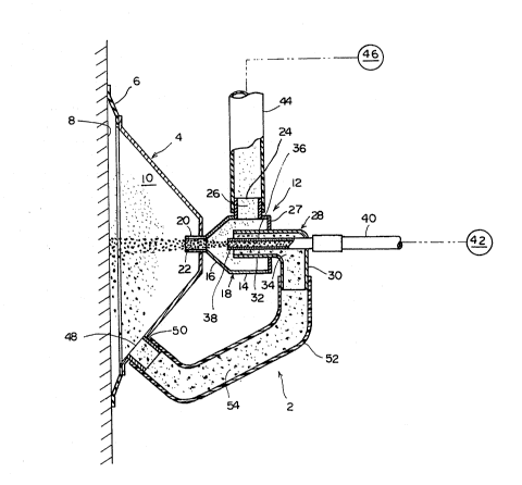
Figure 1 is a sectional view showing the principal parts
of the cleaning device of this invention;
Figure 2 is a diagram showing variation in the amount of
the cleaning material impinged against a surface to be
cleaned by the cleaning device of Figure l; and
Figure 3 is a sectional view showing a modified example
of a cleaning head in the cleaning device of Fiqure 1.
Preferred embodiments of the cleaning devi~e of the
invention will be described in detail with reference to the
accompanying drawings. -
With reference to Figure 1, the cleaning device shown -~
generally at 2 includes a closing member 4 which may be of a
nearly frustoconical shape. The closing member 4 is formed of
a rigid material such as a steel plate. A partitioning wall
6 is disposed in the annular free end portion of the closing
member 4, and extends forwardly while inclining radially
outwardly. The partitioning wall 6 is formed of a
5 --
.~ - .
. .
, ~ - . : : : ~ . ~
1 325954
- 6 -
flexible material such as natural or synthetic rubber.
As Figure 1 clearly shows, the closing member 4 having
the partitioning wall 6 is positioned opposite to a
surface 8 to be cleaned by contacting the free end
portion of the partitioning wall 6 with the surface 8,
and in cooperation with the surface 8, defines a
pressure-reduction space 10. As will be described
below, the pressure-reduction space 10 is evacuated to
maintain it in a pressure reduced condition. The
closing member 4 therefore suction-adheres to the
surface 8. A plurality of wheels to be contacted
intimately to the surface 8 and a driving source (not
shown) for driving the wheels are also mounted on the ~ ~
closing member 4. Accordingly, the closing member 4 -- -
suction-adheres to, and simultaneously travels along,
the surface 8. For details of the suction-adhering and
travelling of the closure member 4, see U. S. Patent -
4,095,378 cited herein as prior art.
A cleaning head 12 is fixed centrally to the
rear side (right side in Figure 10) of the closing
member 4. The cleaning head 12 is constructed, for ~-
example, by proper metal working or casting and;~
includes a housing 18 comprised of a cylindrical rear ~ -
portion 14 and a frustoconical front portion 16. A
25 forwardly projecting cylindrical member 20 is disposed -
at the front end of the housing 18 and defines a first ~
nozzle flow passage 22. The cylindrical member 20 ~-
defining the nozzle flow passage 22 extends through the
closing member 4, and the tip of the nozzle flow
passage 22 is positioned within the pressure-reduction
space 10. An opening is formed in the upper surface of -
the cylindrical rear portion 14 of the housing 18. A - - -
cylindrical member 24 defining a outflow passage 20 is -
disposed extending upwardly from this opening. A
35 member 28 is disposed in the housing 18 extending - ;
1 325954
-- 7
through its rear wall 27. The member 28 extends in an
L-shape, and has an upstream portion 30 extending
upwardly from its inlet end and a downstream portion 32
extending forwardly from the upstream portion 30
through the rear wall 27. The member 28 may have a
circular cross-sectional shape, and defines a re-
impinged cleaning material inflow passage 34. A
cylindrical member 36 of a relatively small diameter is
also disposed in the cleaning head 12. The cylindrical
member 36 extends from rearwardly of the curved portion
of the member 28 (the boundary between the upstream
portion 30 and the downstream portion 32) and through
the downstream portion 32. The cylindrical member 36
extends concentrically with the cylindrical member 20
and substantially straightforwardly. The cylindrical
member 36 defines a second nozzle flow passage 38.
Accordingly, in the illustrated embodiment, the first
nozzle flow passage 22 and the second nozzle flow ; -~
passage 38 extend substantially straightforwardly and
concentrically with each other. The downstream portion
32 of the re-impinged cleaning material inflow passage
34 extends outwardly of, and concentrical]y with, the
second nozzle flow passage 38. It is critical that the
cross-sectional area Sa of the first nozzle flow
passage 22 should be sufficiently larger than the cross
sectional area Sb of the second nozzle flow passage 38.
Preferably, Sa=2 to 8 Sb. -
The inlet end (upstream end) of the
cy~indrical member 36 defining the second nozzle flow
passage 38 is connected to cleaning material feed means
42 via a flexible hose 40. The cleaning material feed
means 42 may be of a known type, and includes a
compressor pump and a source of supplying a cleaning
material. It feeds a pressure fluid stream (which may
be, for example, a compressed air stream) containing
1 , . . : . . .
.. - . - - . . ..... : : - . ...... . , . . : .
- . - :- ; - .- ,, : . . , . ~-
- . :. ~ : . . .. .
1 325q54
- 8 - ~ .
the.cleaning material to the second nozzle flow passage
38 through the flexible hose 40. If desired, it is
possible to include the cleaning meterial into a liquid
such as water instead of the compressed gas stream and :
thus feed the cleaning material. The inlet end
~upstream end) of the cylindrical member 24 defining
the outflow passage is connected via the flexigle hose
44 to suction means 46 which may be a vacuum pump. The
suction means 40 sucks a gas ~or a liquid) from the out :~
flow passage 26 through the flexible hose 44. A
discharge opening 48 is formed in the closing member 4 ~ :~
which defines the pressure-reduction space lO in -:
cooperation with the surface 8. A cylindrical member ~ .:
50 projecting rearwardly from the discharge opening 48 .;- - .
15 is disposed. The cylindrical member 50 is connected to .~
the inlet end (upstream end) of the the member 28 by : .-
means of a pipe 52 (which may be made of a synthetic
resin or rubber). The pipe 52 and the cylindrical -~ -
member 50 constitute a re-impinged cleaning material
20 return passage (return means) 54 for returning the . ~
cleaning material, which has been impinged against the -
surface 8, to the re-impinged cleaning material inflow . .
passage 34 defined by the member 28.
The operation and advantage of the cleaning - .:.:
25 device described above will now be explained. To clean ~--
the surface 8, a pressure fluid stream containing the
cleaning material is fed to the second nozzle flow .
passage 38 from the cleaning material feed means 42 via . :` .
the flexible hose 40. The compressed fluid stream
30 containing the cleaning material passes through the :-
second nozzle flow passage 38, advances into the first
nozzle flow passage, and is impinged against the
surface 8 from the first nozzle flow passage 22. In
the meantime, the suction means 46 commun.icating with . .
the outflow passage 26 via the flexible hose 44 sucks
' "
- :... . ~ . .. . . . .. . ... : .
1 325~54
_ 9 _
the fluid from the pressure-reduction space 10 through
the re-impinged cleaning material returning passage 54,
the re-impinged material inflow passage 34, the space
within the housing 18 and the outflow passage 26. As a
result, the space 10 is reduced in pressure. When the
pressure fluid stream containing the cleaning material
comes into the first nozzle flow passage from the
second nozzle passage 38 and flows through the first
nozzle flow passage 22, the first nozzle flow passage
22 acts as a mixing chamber in an ejection to crease a
sucking action at the inlet portion (upstream portion)
of the first nozzle flow passage 22. Accordingly, the
fluid in the pressure-reduced space 10 is not sucked
into the housing 18 via the first nozzle passage 22.
lS The cleaning material which has been impinged against
the surface 8 and performed a cleaning action flows
through the re-impinged material cleaning material -
returning passage 54 while being entrained in the fluid
flow sucked from the space 10, and is returned to the
re-impinged cleaning material inflow passage 34. The
returned cleaning material flowing through the flow
passage 34 flows into the space within the housing 18
and a portion of it advances into the first nozzle flow
passage 22 by its own flowing inertia and the sucking
action created at the inlet portion of the first nozzle
flow passage 22, and is again impinged against the
surface 8. A portion of the remainder of the cleaning
~aterial which has been returned to the space within
the housing 18 from the re-impinged cleaning material -
flow passage 34 is entrained by fluid stream sucked
through the discharge flow passage 26 and the flexible
hose 44 and fluidized. Generally, the cleaning
material undergoes breakage by collision with the
suface 8 or otherwise. Since the broken cleaning
35 material has a relatively large surface area for its ~-
.:
.
,-,.- -:. :.:: . . . - - -.: . . .. - ,... .- :, ~.. : . . . ; . . .
1 325~54
-- 10 --
weight and does not much flow by its own lnertia, the
broken cleaning material tends to be entrained in -the
sucked fluid stream and drawn through the outflow
passage 26 and the flexible hose 44 without entering
the first nozzle flow passage 22. On the other hand,
the cleaning material which retains its good cleaning
properties without breakage has a small surface area ~ -
for its weight and flows well by its own inertia.
~ccordingly, it tends to enter the first nozzle flow
passage 22. Foreign materials, paints, rust, etc.
which are peeled or otherwise removed from the surface
8 are entrained in the fluid stream sucked from the
pressure-reduction space 10 and drawn through the re
impinged cleaning material return passage 54, the re-
impinging cleaning material flow passage 34 and theoutflow passage 26. The flexible hose 44 connected to
the outflow passage 26 may be caused to communicate
with the suction means 46 via a known mixture
separating device (not shown) so that the cleaning `~
20 material, contaminants, paints, rusts, etc. are -
separated from the suction fluid stream in the foreign
material separating device. The partitioning wall 6
disposed in the closing member 4 makes contact lightly
or intimately, but the space between the partitioning
wall 6 and the surface 8 is never sealed up tightly.
When the inside of the pressure reduction space 10 is
maintained under the reduced pressure, some fluid flows
into the pressure reduction space 10 from between the
partitioning wall 6 and the surface 8.
Accordingly, in the cleaning device 2 of the
invention, not only the cleaning material originally
contained in the compressed fluid stream fed into the
second nozzle flow passage 38 from the cleaning
material feed means 42 but also the cleaning material
returned to the re-impinged cleaning material inflow
- . -- : ; . . - . - : . -: - - - : . : . . . . - - . . . . . .. .. . . . . .
- . - . : ~ . - . . .:
: . : , :. . ~
1 325954
-- 11 .
passage through the re-impinged cleaning rnaterial
return passage 54 are impinged against the surface 8
from the first nozzle flow passage 22. Thus, as
compared with a conventional cleaning material in which
the cleaning material is not re-impinged against the
surface 8, the amount of the cleaning material impinged
against the surface 8 is increased and thereby the
cleaning efficiency is improved.
If the amount of the cleaning ~laterial fed
to the second nozzle flow passage 38 from the cleaning
material feed means 42 is M kg/min., the rate of re-
impingement of the cleaning material is R~ and the
number of re-impingements of the cleaning material is
n, the amount of the cleaning material impinged per
minute is as follows:
F(n) = F(n-l) x R/lO0 + M
Figure 2 is a diagram showing the variations of the ~ -
amount of t~e impinged cleaning material for M=35 and
R=50, 60, 70 and 80 respectively, which were calculated
by a computer. In Figure 2, the axis of ordinates
indicates the amount of the cleaning material impinged
(kg/min. SDD) and the axis of abscissas, the number of
re-impingements. It is seen from Figure 2 that when R
is constant, the amount of the cleaning material
impinged is stabilized within a specific range if time
passes beyond a predetermined period of time. In the
cleaning device 2 described above with reference to
Figure 1, the re-impinging rate of the cleaning
material can be properly adjusted by, for example,
30 varying the amount of the fluid stream to be sucked -
from the flow passage 26 by the suction means 46, the
amount of the fluid stream to be fed to the second
nozzle flow passage 38 from the cleaning material feed
means 42, or the distance between the first nozzle flow
passage 22 and the second nozzle flow passage.
-::
- ., . , - , . .. . . . . . . .
1 32595~
Figure 3 shows a modified example of the cleaning head.
In a cleaning head 112 shown in Figure 3, a cylindrical
member 120 defining the first nozzle flow passage 122 and a
cylindrical member 130 defining the second nozzle flow
passage 138, as in the embodiment shown in Figure 1, extend
substantially straightforwardly and concentrically with each
other with a distance therebetween in the left-right -
direction in Figure 3. On the other hand, a cylindrical
member 124 defining a flow passage 126 extends inclinedly
rearwardly and upwardly from between the upstream end of the
first nozzle flow passage 122 and the downstream end of the
second nozzle flow passage 128. A re-impinged cleaning
material flowing passage 134 is defined by the cylindrical
member 128. The cylindrical member 128 extends rearwardly and
downwardly from between the upstream end of the first nozzle
flow passage 122 and the*.downstream end of the second nozzle
flow passage 138. The other structure of the cleaning head
112 shown in Figure 3 is substantially the same as the
structure of the cleaning head 12 shown in Figure 1, and
therefore, a description of the other structure will be
omitted herein.
In the case of using the cleaning head 112 shown in
Figure 3, too, the cleaning material impinged against the
surface from the first nozzle flow passage is returned to the
re-impinged cleaning material inflow passage 134. Thereafter,
a portion of the returned cleaning material again enters the
first nozzle flow passage 122, and is again impinged against
the surface from the first nozzle flow passage 122. Another
portion of the returned cleaning material is discharged while
being entrained in the fluid stream sucked through the
outflow passage 126.
- 12 -