Note: Descriptions are shown in the official language in which they were submitted.
- 1 326 1 51
8TRUCT~RAL FRANB FOR 8EPARATB NIP8 I~ A PRB98 8ECTION
The present invention concerns a frame
construction for a press section of a paper machine in
which there are at least two, preferably three
- 5 successive and separate press nips in a direction of
running of the web from which water is removed, the
press nips substantially dewatering the web and being
formed between two opposite press elements such as
press rolls. The web runs through these nips supported
by a dewatering and/or transfer fabric.
In prior art press sections of a paper
machine such as the Valmet so-called Sym-Press (TM)
press section, there have been horizontal beams above
the press rolls both at the service side and at the
operating side of the paper machine, which connect the
front frame and the rear frame of the press section
permanently together. In this connection and also in
the following description, the front frame means the
frame part that is situated in the running direction of
the web at the front side, with a pick-up suction roll
of the press being fixed, e.g., to the front frame. In
a corresponding manner, the rear frame means the frame
part situated at the rear side of the press section,
i.e. closer to the drying section.
~ 25 From the Valmet U.R. Patent Applications No.
- 2,127,448 and Canadian Patent Nos. 1,278,448 and
1,268,649, paper machine press sections provided with
separate press nips are previously known in which there
are two or three succeeding, separate press nips in a
running direction of the web substantially dewatering
the web, these nips being formed between two press
rolls. The web runs through the nips between two
fabrics. At least in the first one of the nips, the
dewatering takes place through both faces of the web as
the nips are formed between two hollow-faced press
rolls or between a hollow-faced roll and a smooth-faced
roll. In the press section, the first upper or lower
;~,
t~ ~
' ~
. . .
1326151
fabric acts as a pick-up fabric, onto which the web is
transferred from the forming wire.
According to the Valmet Finnish Patent
Application No. 823187, it is considered an important
S feature in the press section described therein, that
the press section includes two upper fabrics and two
lower fabrics. The first fabrics in the running
direction of the web are press fabrics that receive
water, and are arranged in a manner such that one of
these first fabrics acts as a press fabric in the first
nip, and the other fabric acts as a press fabric both
in the first nip and in the second nip.
According to Fig. 3 of U.K. ~atent No .
2,127,448, the press section is provided with a front
frame, a rear frame, and with an intermediate frame
between the same, these frame parts being
interconnected by means of horizontal beams situated
both at the service side and at the operating side of
the paper machine. These beams interconnect the
vertical frame parts above the press rolls. Under
t~ese circumstances, the concerned frame part is
permanently fully closed from above, which ma~es the
replacement of the press rolls and of the various
fabrics more difficult and slow.
In connection with the prior art frame parts
of these press sections, difficulties and relatively
long standstills have occurred in relation to the
~; replacement both of the press fabrics and of the press
rolls. These problems have been increased with an
increase in the widths of the paper machine, in
particular because the press rolls have become much
longer and heavier. These problems have also been
increased by the fact that press fabrics which are made
of plastic material and which are rigid in the
transverse direction thereof, has started being used
ever increasingly. These press fabrics cannot be
jammed into a bundle because of their rigidity.
,.,~
3~ 1326151
Accordingly, the present invention is
directed towards elimination of the difficulties and
problems noted above with respect to the prior art
structures and towards further development of the frame
constructions of press sections provided with separate
nips, so that the replacement of the press rolls and of
the various fabrics can be made considerably easier and
faster.
The present invention is also directed
towards the provision of a frame construction in a
press section of a paper machine provided with separate
nips that is essentially shorter than prior art frame
constructions. By shortening the frame construction,
investment costs both in the paper machine and in the
paper mill can also be decisively reduced in other
respects, because a paper machine hall of shorter
length in the machine direction is required.
In accordance with one aspect of the present
invention, there is provided a frame structure in a
press section of a paper machine having, in a running
direction of a web from which water is removed, at
least t~o separate press nips formed by respective
separate pairs of press rolls substantially dewatering
th~ web and being formed between opposite press
elements through which the web runs supported by a
fabric, comprising a front frame and a rear frame
separate from and unlinked to one another and defining
a permanently open space therebetween above the two
separ~te press nips which is situated for use in
replacement of fabric and press elements; the front
frame having a rear part at which an upper press
element comprising one of the press rolls of one of the
nips is mounted; and the rear frame having a front part
at which an upper press element comprising one of the
press rolls of another nip is mounted; an intermediate
frame situated between the front and rear frame and on
~'
-` 1326151
3a
which both a, first lower roll of one of a first pair of
press rolls forming a first press nip and a second
lower roll of a second pair of press rolls forming a
second press nip are supported: and a plurality of
intermediate parts disposed between the intermediate
frame and the first and second lower rolls, the
plurality of intermediate parts being movable so as to
open and to load one of the first press nip and the
second press nip.
Accordingly, a frame construction or
structure of a press section provided with separate
nips in accordance with the present invention, is
principally characterized by a front frame and a rear
frame
",
I
" 1 3261 51
separate from one another, between which a space is
provided which is substantially open at the top. This
free space is arranged so as to be utilized in
replacement of both of the upper press and/or transfer
fabrics and of the press rolls. At least an upper roll
or corresponding press element of a first or second nip
in the press section is attached in conjunction with a
rear part of the front frame, and at least an upper
roll or corresponding press element of a second or
third press nip in the press section is fitted in
connection with a front part of the rear frame.
- Due to the present invention, faster replacement
of the rolls in a press section and in particular of
the press and transfer fabrics, is quite significant in
view of the production output of the paper machine,
because the durations of standstills resulting from the
replacements of press rolls and fabrics can be made
essantially shorter. In particular, the replacements
of press fabrics must be repeated at quite short
intervals.
It is a further advantage of the invention that at
the service side of the paper machine, an equally
abundant space is not needed as when closed frame
constructions of a press section are used, ~ecause the
rolls, at least heavier rolls, can be lifted above the
frame construction of the press section and, if
necessary, be turned thereat to a position parallel to
the machine direction. In the latter case, so-called
center lifting of the rolls is preferably used.
The present invention will now be described
in grèater detail below, with reference to exemplary
embodiments thereof illustrated in the accompanying
drawings, and to which the present invention is not
intended to be strictly confined. In the drawings,
Fig. l is a schematic side view of a first
embodiment of the present invention;
,~ ,
1326151
Fig. 2 is a schematic side view of a second
embodiment of the present invention;
Fig. 3 illustrates replacement of fabrics as
applied to the press section of Fig. 1; and
Fig. 4 illustrates replacement of rolls as
applied to the press section of Fig. 1.
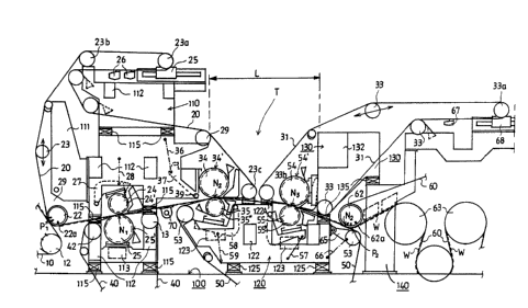
According to possible exemplary embodiments
of the present invention shown in Figs. 1 and 2, a web
W is formed on a wire 10 which is either a fourdrinier
wire or the carrying wire in a twin-wire former. On a
downwardly slanting run of the wire 10 between a
suction roll 11 and a wire drive roll 12, the web W is
transferred at detaching line Pl on a suction zone 22a
of a pick-roll 22 and onto a first upper fabric 20
which is both a press fabric that receives water and a
pick-up fabric.
The fabric ~0 carries the web W on a lower
face thereof into a first press nip N~ which is formed
between two press rolls 24 and 25. The nip Nl is
provided with two press fabrics, i.e. the upper fabric
20 and a first lower fabric 40 which is a press fabric
that received water. According to Fig. 1, the upper
press roll 24 in the nip Nl i5 provided with a hollow
face 24' that receives water. The lower roll 25 in the
nip Nl is a hollow-faced 25' press roll with a
. .
1~ `
- 1326151
diameter prefQ~bly slightly larg-r than the diaroeter of the upper
roll 24. One of the pre~s roll~ 24 and 25 can also be a
pre~s-~uction roll. One or botl~ of the pross roll~ 24;25 l~/are
provided with a drivs. In the ~irst nip N~, the dewatering tak~
; place through both fac-s o~ ~hR web W both into th- upper fabric 20
ana into t~e lower f~bric 40.
~; Art~r ~e firs~ nip ~1~ in th~ run of the web w, ther~ is
a second ~eparate nip N2 wh~ch i~ for~ed betw~en two pres~ rolls 34
and 3~. Accord~n~ to Fig. 1, t~ firat uQper fabric 20 carrle~ ~he
w-b N on a low~r facQ into tbe ~cond nip N2. ThH web W following
~long wit~ th8 upper ~a~ri~ 20 and not with ~he low~r fabric 40 ~fter
the ~ir~t nip N~ ~nsur d by ~ean~ o~ well-known ~rrangements.
According ~o Fig. 1, in the second nip N2 the lower fabric i~ a
p~rticular trans~er fabric ~0 whic~, compared to the press fabri~
propcr, i8 r~latively or fully impervious and which fully or
~ub~tantially doe~ not recoive water Thu~, in ~ig 1, the
dswat~ring t~king plac~ in the ~cond nip N2 i~ primarily toward~
tho fir~t ~a~ric 20, ~ o upuardly Due to the surface prop~r~ies
(~uootbne-s and adhesion) o~ the tran~fer fabric 50, and due to th~
~rr~ng~oQnt~ ~ich ~$11 be ~urthor explain~d b~low, ~he web W
accord~ng to Fig 1 follows along with tho ~ran~f~r fabric 50 whlch
carrio~ the web W into a third, separate dewatering pre3s nip N3 in
the pr ~ ~ection
According ~o Fig. 1, a ~econd upper fabric 31 is a pre~s
~elt ~hich receive~ wat-r and which runs throuqh the nip N3 Th-
upper S~bric 31 is guid~d by guid~ roll- 33, 33a and 33b and
reconditioned by devices 67
According to Fig a, th- w~ W i~ arranged to follow along
with a ~irst lower ~bric 51 a~tor the fir~t nip Nl, whiah carries
-6-
1326151
~he web w on ita upper f~ce into the -cond ~parate nip N2. Thls
nip N~ i~ formed b~twe~n ~wo press roll~ 34 and 35, with the roll
35 ~eing pro~id~d w~th a hollow faced 35", and the roll 34 being
provid~d wit~ a ~ollow fac~d 34'. In Fig. a, th~ ~econd nip N2 is
al~o provid~d wit~ two f~brics, with A low~r f~bric being th~ fir~t
lowe~ f~bric 51 whic~ i~ a pres~ fabric t~at rece~ves water and is
perviou- to water, ~.g. an ordinary prc~s folt. A~cording to Fig. 2,
the upper fabr~c ln the ~eoond nip N2 ~ ~ pr~s~ fel~ 30.
According ~o Fig. 2, thc d-wat~ring takes plac~ both
upwardly ~nd do~nwardly in th~ nip N2. Af~e~ the nip ~2~
~ollowing of the wab W along with tha upper presa felt 30 i~ ensured,
e.g., by nean~ of t~8 felt anglos or by m-~ns of a ~uction device.
Tho w b W ~ passed into A third nip N3 in the pre~ section along
wtt~ t~a upper prass felt 30.
According to Fig. 2, the thir~ nip N3 whic~ i~ a separ~te
n~p and t~- la~t ~ub~tanti~lly d~wat~ring nip in t~e pr~ss s~ction,
iB fon~Rd bQtween two pre88 roll~ 5~ and S5, one of wh~ch i8 provided
w~th a hollo~ face S~ and ~ho othor ono with A ~mooth fAce 55~.
A~cord~ng ~o F~ , in the third nip N3 the lower f~bric i8 a
~ran8~r fabrla 50 ~nd the upper f~bric is ~ pres~ fabric 31 that
r~coivo- w~t-r. According to Fig. 2, t~o upper fabri~ is a press
: folt 30 and aftor the nip ~3, ~e web W ~ollow~ along with the
s~ooth-faced 55' ~owor roll 55, from w~ch the web W is detached and
tr~n~rr~d as an opon dra~ Wp onto the drying fabric 60 in a
~ulti-cylinder dryer.
According to Fig. 1, the tran~fer fabria S0 carries the web
W ~ter th~ nip N3 onto a tran~fer-~uction roll 62 over whose
~uction zon~ 62~ t~ drying wir- 60 in the drying ~ection of the
p~p r ~achine is passod. Tho web W is tran~fer~ed at the line P2,
: -7-
t326151
by the eff~ct of a ~uction zona 62a, from the transfer ~abric 50 onto
tbe drying wire 60 and onto w~o~- rac~ t~e web w i~ ~ade to adhQre.
The drying wir~ 80 pas~es over a ~irst drying cylind~r 63 or a
corre-ponding lead~cylinder in the drying ~-ction. Tbe web W
proce~d~ along it~ run b~inq supported by the drying wir~ 60, as a
so-called singl~-fabric dr~w, at lQast in ~he initial part of the
drying ~Qction.
In Fig~. 1 and 2, t~e quid~ roll~ of th~ fir~t uppar fabric
20 arQ denoted by r~f-r~nc- nu~ral~ 23, 23a, 23b. Correspondinqly,
in Fig. 1, and in t~o runnin~ direction of th~ w~b W, the f~r~t guide
roll o~ the ~rst low~r fabric 40 i8 denoted by reference numQral ~2,
~nd tn~ other guid~ roll3 by r~ferenco numeral ~3. The guide rolls
of tho ~cond upp-r fabric~ 30, ~1 ar~ denoted by r~f~r~nce nu~erals
33, 33a, 33b, whil- t~ guide rolla of t~e lower fabrics 50:51 are
denotQd ~y reference numeral 53.
Aceording to ~iq8. 1 and 2, a stoa~ box 70 i~ fitted between
the first ~1 and socond N~ nips, to op-rat- aqain~ the web W,
~ith ~ea~ ba~n~ appl~-d into tho stea~ box 70. ~h~ functioning of
t~- teae box 70 i8 known in a m~nner in and of ~tself, for
int-n-ifylng t~o da~ataring.
A fra~a con-tructlon in accord~nce with the pre~ent
invention ~ill be describ~d belo~, which i~ synergic with the press
concept~ described ~bov~, and by ~hich an ~i-r and faster
r plac~nt of pr~s f~brics and pre~s rolls, as well as
const~uctional adv~ntages/ aro achieved. ~h~ fram- con~truction in
~ccordance ~ith Figs. 1 And 2 conprise~ a front fra~ 110 constructed
aa upportad on foundat~ons 100 of the paper machine hall, an
int-r~ dl~te frama 120, and re~r ~rame~ 130 and 140. Moreover, in
F~. 2 th~r- i~ a th~rd r~nr fra~ part 150. At a front side of the
-8-
.
- 1326151
~ront frame l1o, t~r< i~ a pro~action pArt 111 on which th- guid~
roll a3 of ~e fir~t fabric 20 and th~ pic~-up-suct~on roll 22 are
support~d, th- uction roll 22 ~y ~anc o~ loadlng arm~ 29 The
~ront fra~e 110 is provid~d with cantilever-d tran~v~rse beam~ 112.
Moreover, th- s~rvicQ-side ~id~ frame of the front frame 110
provided with op-n~ble inter~diat- pieces 115
-~ Th~ interm~diate frame 120 co~pri~e~ canti}ev-r-d transver~e
beam~ 122 The guide roll 23c of ~he fir~t fabric 20 and the guide
roll 33b of the third fabr~c 30i31 are mounted on an upp~r side 121
o~ th- intarmedi~te frame 120 through supports 122A The sid~ frame~
of t~e intor~-diate fra~e 120 at the ~er~ieing ~id~ are provided with
op~nable lntermediat- piece~ la5
The rear ~ram~ 130 comprisas cantil-ver-d ~ransversQ b~ams
132 as w-ll a~, in tha ~ide fra~es at ~he ~ervicing sida, openabl~
intarDed~Ate pi-ce~ 135
It is char~ctcri~tic of the fra~o part~ in accordance with
ebe pre~nt inv-ntion that bet~eon the ~ront ~rame 110 and the rear
fr~oe 130, i a ~bove the r lativ-ly lo~ intermediate fra~o 120,
there ia an opon ~pacQ ~r In oth r words, ~he ~ront ~rame llo and
the rear Sraae 130 are not interconnect~d at the upper part~ of the
fr~e, at l-a~t not by ~eans o~ ~tronq fr~e ~eama prop~r ~he open
~pace ~r c~n bo ut~ d in the presen~ inv ntion in a number of way~,
as ~ill be d ~cribad ~n greater detail belo~
A~ can be not-d i~ediately from Figs 1 and 2, th~re ar~
nip- at bot~ ~ide~ o~ t~e opon sp~ce T~ na~el~ the ~econd and third
nip N2 ~nd N~ in Flg 1, a~ well ~- tha fir~t and th~ sccond nip~
Nl and N2 in Fig 2 Moreover, th-r- is al~o an open space ~
in Fig ~ betw -n t~e for~er xear ~ramc ~30 and the latter r~ar frame
1~0 ~bove the nip N3 Th- rolls of the third nip N3 can b~
r-placod t~rough thi~ apace T~
~ 1326151
According to F~g. 1, tho pr--s roll~ 24 a~d 25 in the ~ir~t
n~p Nl are rount~d in~idQ the front fra~ 110. The upp-r pr~
roll 24 i8 ~ttach-d to an artlculat~d int-r~ediate part 27 wh~ch can
bQ displaced by ~ean~ or power un~ts 28 for the purpose of opaning
and clo~ing and lo~ding of th~ nip Nl. Aocording to Fig. 1, the
upp-r roll 34 in th~ ~-cond nip N2 is su~ort~d on an articulat~d
inter~ediate p~rt 3~ which c~n b- pivotQd by ~ean~ o~ pow~r un~t~ 36
80 as eo facilitat~ th~ rap}acement of th~ folt 20 or, i~ rQquir~d,
~o as to open ~he nip N2. Th~ loading of th~ nip N2 takea placR
primarily by ~eans o~ pow-r unit~ 59 of th~ low~r roll 35.
Accordinq to Fig. 1, th~ upp-r roll 34 in th~ ~-eond nip
N~ ~ ~ounted on the rear s~d~ of tha front fram~ 110. T~e low~r
roll 35 of th~ ~ cond nip N2 i~ support~d on in~er~ediat~ part~ 58,
wh~ch c~n be displaced by ~eanc of the power units 5g so as to opon
and to load th~ nip N2. Furt~eroor~, according ~o Fig. 1, thQ
upp~r roll 54 of tho third nip N3 ia ~ount-d in ~tationary bearing
~upport8 pla~d on tho front side o~ the rear frame 130~ on the
other h~nd, the louer soll 55 of t~e third nip N3 i~ oupported on
intern~di~t- part~ S6 ~lch cAn b~ pi~ot-d around an articulat~d
~oint by neAns o~ po~ r unit~ 5~ in connection with the ~ntermediatQ
fra-~ 120, o a~ ~o load and to open the nip N3 In Fig 1, the
tr~nsfer-#uction roll 62 1- mouneed on the rear fram 140 ~y mean of
~t~tionary bearin~ ~upport~, and th- guide roll 53 for th~ fabric 50
pl~cod und-rneath the roll 62, i~ attacb-d to articulated
int-roed~ate p~rt 65 ~hic~ c~n be plvoted by ~eans o~ powe~ units 66
in conn ation vith the intermediate frame 120
According ~o Fiq 2, th~ fir~t nip Nl iY situated in the
~aoe location a~ th- oecond nip N2 in Fi~ 1 According to Fig 2,
th- upper roll 24 of the firot nip Nl i~ mounted o'n in~ermediate
--10--
,
~ 1326151
part~ 37 which arQ connected to t~o front ~ide of the front fra~e llo
by mea~ of articulAt~d joints 39, being pivot-d by mean~ o~ pow-r
unit- 3~. In Fig. 2, th~ int~rmediate frame 120 i~, in the m~chin~
dir ct~on, longer than in Fig. 1. According to Fig. 2, thQ upper
roll 34 o~ th~ ~cond nip ~2 i~ ~ountod on int~rmediatB parts 71
which are loaded by powor units 72. T~ inter~ediate part~ 71 ~re
~ount~d at the proxi~ity of tne front side of tho rear ~rame 130 by
mean~ of ~rticulated ~oi~t 73 pl~c-d therQat. In other words, th-
~ir~t nip Nl is s~uated ~n connection with th~ rear side of the
fron~ }r~n 110, ~nd th~ ~-cond ~ip N~ ~ fitted in conn-c~ion with
the front ~ide of tho ro~r ~r~m 130, ei~er stationarily or through
intor~ a~o part~ 37, 71 whic~ a~ att~chod to tb~ front frame 110
and~or to the rea~ frame 130 ~y m~n~ Of Articulat~d joints 39, 7~.
According to Fiq a, tbe third nip N3 i8 placed abovo the
rear fr~o 14~ Th~ lowor roll 55 of th- third nip N3 i8 mounted
on the rear fra~o 140 And t~ upper roll 54 i~ mounted on
inter~diate part~ 74 ~hioh can be pivotQd by ~eans ot power units 75
~round the articulat~d ~oint ~6 Th~ ~oint 76 is placed in
conn~ction ~ith tbo r~ar ~ido of the r-ar frame 130 Finally, the
fr~m part inelude- a tnlrd r~ar fra~e 150, with the tr~nsfer roll fi2
and t~e gulde roll 33c rOr the f~brio 30 being permanontly or
rt~tionarily ~ount~d to a ~ront id~ th~reof
Rep~ceaont of difforent fabric~ in conn-ction with the
fr~ue ~tructure ln accordance ~itn the pre~ent invention, will b~
de~crib-d b~low ~t~ re~-r~nce to Fig 3
Wh-n th- upp r fabric 20 i8 being replacêd, the old fabric
i~ removed and tho intermediat- piec-8 115 ar- opened ~o that free
int~r~ diat- paees 115A are opened at the area of the ~ervice ~ide
of th- front fr~m- 110. The suction roll a2 is di~placed to the open
--11--
~` 1326151
po~ition 22A. The pre~ roll~ pl~c-d in~id- tho fabr~c loop 20 arQ
8hift~d to positions 24A And 34A that open the nip~ Nl and ~2 by
pivoting the intermediate par~ 27:37 by moan~ of the pow-r units
28;36 In order that all the roll~ to be plac-d in~ide the loop of
th fabric ao can bo brought suffici~ntly clo~e to one ~noth~r, thQ
upper guid~ roll 23a ~hic~ is support~d on t~ t-n-ioning means 25 ~3
di~placed to i~B par~ing Sito at po~ition 23A~ By the sa~e tok~n,
tho oth~r guid~ roll 23b 8~ tuatsd ab~ve the front frame llo 1
displacod to a parking sito in po~ition 23B, ~upported on thQ
pro~eotion part 111 of the fra~o. T~e rol~ 23c i~ di~placed nlon~
routo C to t~- po~i~ion 23C~
When the piCk-up point Pl and th~ nip~ Nl and N2 are
opened, and w~en tho rolls 23a, 23b and 23c ar- in their inner
position~ 23A, 23B and 23C whllo t~o inte~ediate piece~ 115 ar~
op n~ t~ fabric loop is pae~d through tho intermedia~o spac~s 115A
at the ~ide fr~o at tho ~rvicing ~d- ~o that it forms a loop 20A
a~ ~o~n in Fig. 3~ having bQen opQned f~o~ the fabric roll 200 which
i~ pl~ced on t~ r plac-m nt pol- 20~. The replacement pole 205 i~
auw orted ~ro~ both o~ it~ nda by m an- o~ lifting wireH 210, which
A~O att~ched to ~ho traverae crane ~not illu~trat~d) in the paper
~achln hall. Th~ loop 20A i8 then ~pread out by unwinding the
~abrio 20 froD the t~o~old roll 200 to i~ ~ull width and lQngth by
alt~rnatln~ly di~placing th~ guide rolls 2~A, 23B and 23C to th~ir
nor~al op rating po~ition~ along th- route A, B and C. After the
~brl¢ 20 ha~ boen ~proad out and t~n~ion~d, tho pick-up point P
i8 closQd along ~ith the nip~ Nl and N2 and th~ int~rm diat-
pi~ae~ 115, and ~e fabric 20 are tightened.
Wh-n th~ ~ir t low-r ~abric 40 i6 b~inq replaced, the guids
roll located in the base~ent ~pace i8 di~pla~ed to upp-r po~ition
-12~
1326151
42A, int~rm~dlat~ piece~ 115 are op~n-d, and th~ fabr1c loop 40A i~
pa~d fro~ the roll 400 around t~- beam~ 112, 113, th~ pre~a ~o~l 25
and the guido roll~ 42 and 13, wheroupon ~he intermediat- pieoe~ 115
are closed, the roll 42A ~ di~placed into the basement space, and
th- fabr~c 40 i8 ten~ion-d
In conn~ctio~ w;th the ~cond lowe~ fabric so, it is
o~p~cially a~vantagsously pos~ibl- to utillze the con~tantly open
~pac- T placed batween th- front and rear fra~ llo and 130 In
order ~o op~n the space T compl~t-ly, the fore~ost guide roll 23c of
the fabri~ 20 i~ dl~placed along t~ route ~ to the parXing ~ite at
position 23C in connect~on ~ith tho r~ar ~ide of the front frame llo
Corre~pondlngly, t~e Sor~o~ gu~de roll 33b of the s~cond upper
f~bric 31 i~ di-placea along the rout~ D to thQ parking ~i~e 33B in
conn-~tion w~th the upper part o~ the rear fr~e 130 W~en the nips
N2 and N3 and the inteDedi~t- pieces la5 are thon in the open
pos~tion, and uhen the roll 53 i~ in th~ inner position S3A hav~ng
been p~oted by ~ an- of e~e power unit 66, th~ fabric loop saA lo
pa-ood around the pro~s and guido rolls to ~e placed inside the loop
50A. T~ guld~ roll 76 or guid~ roll- situated in the basQm~nt space
i~Jare di-pl~c-d to t~e upper posi~ion 76A abov~ the intermediate
~pac~ 125A, 90 that tho roll b~co~ase placed inside th~ fabric loop
SOA.
The roll soo of the fabric 50 i~ supported on the
replac~nt pol- 505. The replacement pol- ~05 i~ supported at bot~
end~ by ~ an~ of lirting wires 510 wh~ch ar- upport~d by the
traverse crane op rating at a ceiling of the pap~r machine hall. At
the same ti~e ~ thQ ~abr~ loop 50A i~ w~dened by unwinding from the
roll 500, tho guide roll or guido roll- 7~A are displaced to th~
lower po~ition and th fabri¢ 50A is spread out to it~ full width ancl
-13-
~ 1326151
l-ng~h, w~orQupon ~he intermediato pieces 125 and th~ nips N2 and
N3 are closed, the guide roll 53A i~ ~hifted to its normal
po-ition, and thQ fabric 50 is tensioned.
Th~ ~econd upper S~bric 31 i- replaced 80 that th~ old
fabric is removed, t~e intermediate pieces 135 are op~ned, and the
fore~ wt guide roll 33b i~ ~hi~t~d along tho rout~ D to its parking
site a~ e~Q positlon ~3B. Corr~spondingly, th- r~armo~t guide roll
33a is ~hift~d along route ~ to it~ parking ~ite at th~ ~ide of ths
roll 33B to t~e position 33A. Afterward~, the f~bric roll 300
~upport~ by ~he replacemQnt pola 305 and ~y tbo lifting wir~ 310,
and ~a~ing been spread ou~ to ~ak~ a loop 31A, i~ pa~sed around the
press roll 54 and tho guid~ rolls 33, 33A ~nd 33a through the
intermediate BpaCQs ~35A. The rolls 33A and 33B are th~n shiftQd
~long t~o routes D and ~ to t~ir operating positions while at the
su~a ti~e unwinding t~o }~bric 31A from t~e roll 300 and spreadinq
it, ~her~upon the nip N3 i- alosed and tho fabric 31 iR tenSionQd
by ~oAn~ o~ the ~en~ioning devices 6~ of tho guide roll 33A.
W~t~in the 8cope of the pre~ent invention, it is also
po~lblo to u~- ~-am~ble pre~- and trAn~fer ~bric~. In ~uch a aase,
the ~r~me parts do not require openable intermediat~ pieces 115, 125
or l~S.
T~- repl~c-~-nt of the pic~-up roll 2a and of th~ various
pr--~ roll~ will b- d-~crib-d below with r~ferencR to Fig. 4. Wh~n
the plck-up roll 22 i8 belng replaoed, it i~ in ~he po~ition 22B and
tb fabric 20 haa been re~ov~d. ~he loop~ 221 of th~ p~ir of lif~ing
wire~ 220 a~e attac~ed to t~e ~xle ~ournal- of the pick-up roll 22~.
The lifting ~ires 220 are attached to the traver~e crane of the paper
~ac~ne ~all.
1326151
The lower roll 2s of the f~r~t nip N~ i~ replaced so that
it i~ d~ch~d ~ro~ it~ bearing upports and ~u~p-nded by mean~ of
i~6 axlo ~ournals on wir- loops 251. Th- roll 25 1~ thon lowered
onto a roller conveyor 80 or quivalent tran~f~r m~ans which ~8
support~d c-n th~ tran~verso b~ 13, z~nd by ~neana of whlch the roll
25 ~ pulled oue to the ~ervico ~id- from in~ide th~ frame part of
the pap-r ~chine. Th upper roll 2~A of the first nlp Nl i~
replaced in a corre~ponding ~anner or in the traditional ~annQr by
~lipping it ~y m~an~ of thrse hooks~
~ he upper roll 34B of t~e second nip la r~placed by
ut~ lng th~ opQn ~paco ~ betwe~n th- fr~e parts 110 and 130.
After th~ ~abri~ 20 ha~ b- n r~ooved, the roll 3~B is ~uspend~d on
~hQ ~ira 3~0 loops 3~1, d~tached ~rcm it~ bearing support~, and
lifted by mean~ of th~ trav~r~ crane abOVQ ~he pr~s sect~on while
m~klng u~ o~ thQ sp~c~ T~
Tno low~r roll 3S of tho second nip N2 i- roplaced ei~her
~y pulling out by mn~n~ o~ the roll-r conveyor 80 r8~ting on ~e beam
12~, or by ~A~ing ~8- o~ t~e ~paCQ T after the roll 34B has b~en
reaov~d, ~y llftlng tho roll 35 u-pend~d on the loops 351 o~ the
llftiDg ~ires by both o~ it~ axle ~ournal-
~
~ he upper roll 54b of the third nip i8 replac~d by li~tingit by ~oans of th- ll~ting loops 5~1 of the lifting wires 540 whil~
N ~lng u-~ o~ t~e sp~co T The lowor roll 55 of tho third nip N3
i- repl~ced eit~-r by l$ftln~ by aean~ of th~ lif~ing-wire loop~ 551,
or by pulling lt out longltud~nally on th- rol~r oonveyor 80 resting
on t~a b am 123, aid-d and supported by the lifting wire~ 551
Instead of the aupporting by the axle ~ournals, which wa~
de~cribed abov-, th~ press roll-, at lea~t the h~aviest roll~, ean
also be li~t-d as ~o-called c-nter lifting, in which the lifting
-15-
takes place by means of one ~ ng5wire which isplaced at the verticle plane of the center of gravity
of the roll to be lifted, the lifting loops arranged in
the form of a downwardly open V being provided around
the roll at both sides of this plane. The center
lifting provides the advantage that the roll can be
turned more freely above the frame construction of the
press section in the machine direction, whereby the
displacement of the roll becomes easier. The new rolls
can be brought to their proper location
correspondingly.
The new rolls are inserted in their location
by performing the operations described above in the
reversed sequence. The roll 25 must be brought to its
location by pushing it longitudinally into the frame
construction on support of the roller conveyor 80 while
one of its ends is supported by a wire loop 251, at
least at the initial stage of the lifting. The rolls
35 and 55 can be brought either throuqh the open space
T or by pushing in on the roller conveyor 80.
In Figs. 1 and 2, the length of the open
space T in the machine direction is denoted by L. The
lengt~ L must bs dimensioned optimally, e.g. so that
the range of the length L is related to the (maximum)
diameter D of the press rolls 24, 34 as follows: L=kD,
- wherein k=about 2 to 5, preferably k=about 3 to 4.
The present invention can also be applied to
press sections provided with an extended nip or
provided wi~h only two separate nips. In such a case,
one of the nips, preferably the latter nip, may be a
so-callad extended nip. In its details, the press
section concept concerned may be, e.g., similar to that
described in the Valmet Canadian Patents Nos. 1,278,448
and 1,268,649.
In principle, a two-nip solution in
accordance with the present invention may be, e.g.,
similar to that shown in Fig. 1 with
. '',..''''.' ,` ~'
` , ` ' ` ;~
't 1326151
t~- ~ir~ nip Nl omitted nnd~ .g., with the th~rd nip replaced ~y
a corre~ponding xtQnded nip or altQrnativ-ly, similar to that shown
in Fig. 1, ~o th~t the third nip and the latte~ rear framo 140 ~r-
omitted ~nd thQ ~cond nip N2 or both nip~ N1 and N2 are
replaced hy corr~cponding ex~ended nips. Al-o, the run~ and ~he
~rrange~ent of ~ha f`abrios and the quality of ~he various fabric~ mAy
differ fro~ above.
When the pres~nt invention i~ appliod, tb- draw of the ~eb W
doos not n~c~9carily h~ve to ~e ~ully closed, even though a clos~d
dra~ adv~ntA~eou~. In ot~er word~, the guid- roll~ and press
roll- o~ correspondin~ pr~ss ele~snts that aro plaoed ~n~ide the
loops o~ t~e upp r fabrios 20, 30, 31 and lower fabric 51 or lowor
fabric ~0, S0, m~y bQ fitt~d in ~ manner in connection with th~ front
fr~e 110, ~e inter~adiate fram~ 120, and th~ rear framee 130, 140
and lS0, ~o that a sub~antially clo~eid draw is obtained $or th~ wob
W fro~ the pick-up point Pl to t~- drying ~ectl~n P2, Wp o~ the
pAper ~ac~ine The n~p~ Nl, N2 ~nd N3 may al~o ha~e larger
~utual dir~e~ncQe ~n hoig~t than what is ~h~wn in F~gs 1 and 2
Tb- ~u e refqrenoe nuoorals denote ~o ~am~ or similnr
co~ponant- t~roughout th~ variou~ f~gur~
Varlo~s detail- o~ t~e pre~nt invontion ~ay vary wlthin the
~eop o~ t~e ln~-n~lvo oonoept- ot fo~th ~bo~e which have been givan
~or ~v nplary purpo~-- only In oth-r word~, the pr-ced~ng
do~crlption of t~e present invontion i~ m-roly exomplary, ~nd i~ not
intended to l~it the ~cop- thereof in any way
-17-