Note: Descriptions are shown in the official language in which they were submitted.
1 326333
ELECTRIC VACUUM CLEANER AND FILTER BAG FOR SAME
The present invention relates to an electric vacuum
cleaner and to a vacuum cleaner filter bag for same.
The changing of filter bags, including the removal of the
full filter bag, requires some dexterity.
It is the object of the invention to improve an electric
vacuum cleaner in a manner which is simple to manufacture, with
respect to the handling thereof and, in particular, in such a
manner that the clean, convenient removal of a full filter bag
is possible.
Accordingly the present invention provides an electric
vacuum cleaner comprising: a fan-motor housing and a chamber
arranged above the fan-motor housing for receiving a filter
bag, the housing having an inlet for receiving incoming air
under suction and an outlet for directing the air to the
chamber; a filter-bag intermediate support, and a swing shaft
about which the intermediate support is pivotally mounted, the
swing shaft being supported by the housing, the chamber being
pivotally mounted to the housing by the swing shaft, the
intermediate support being located between the housing and the
chamber, the chamber having an opening facing the intermediate
support for removable insertion of the filter-bag into the
chamber; a socket connection extending from the filter-bag
intermediate support for connecting the filter bag to the
filter-bag intermediate support, the intermediate support being
carried along upon a swinging open of the chamber about the
swing shaft, the socket connection of the intermediate support
having a valve closure body, and the filter bag being c~pable
1 326333
of separation from the intermediate suppoxt at a point somewhat
beyond a vertical position of a cross-sectional plane of the
socket connection; and wherein the chamber has lugs securing
the chamber to the shaft, the shaft being formed with bevelled
heads located for contacting the chamber lugs, the lugs
bypassing the heads so that the chamber can be removed from the
vacuum cleaner upon pivoted alignment of the lugs with the
bevelled heads by disengagement of the lugs from the swing
shaft.
As a result of this development, the handling of the
filter bags on a certain type of vacuum cleaner is made
substantially easier. The emergence of dust of the falling out
of larger, heavier particles is substantially prevented. The
filter bag can even be changed in the normal position of use of
the electric vacuum cleaner. Handling is made optimal by the
initial automatic separation of the socket attachment
connection by the stopping of the swinging motion of the
intermediate support and the further swinging of the chamber
socket, and the possibility, then established, that the chamber
socket can be disengaged from the swing shaft. In this
way, the entire chamber containing the filter bag can be
detached from the apparatus in an instant. This is not only an
advantage from the standpoint of assembling, but to a
considerable extent also an advantage in use. For example,
the chamber can in this way be cleaned conveniently from
time to time without the entire apparatus being attached to
it. One then proceeds, in a structurally advantageous
- la -
~ 326333
manner, in the way that the detent means are formed of pins
which are under spring action with respect to each other in
outward direction, each of the pins having a beveled trap
head which cooperates with, in each case, a locking shoulder
of journal-pin bearing lugs. This leads to a dependable
detent plug connection which can be loosened at any time. It
is furthermore favorable in this connection for the trap
heads to have a flattened cross-section and for the journal-
pin bearing lugs to have a radial slot adapted thereto. The
corresponding flattening can be used as means Eor fool-proof
attachment. The pins are Éixed against rotation in order to
assure in all cases proper alignment of the position of the
trap head. Easier plug attachment results from the measure
that the radial slot widens outward in funnel shape. A
favorable attachment furthermore results from the fact that
the journal-pin bearing lugs are arranged on the intermediate
support which, in its turn, is mounted, fixed on the housing,
coaxial to the lugs. It is furthermore proposed to provide
the intermediate support with an extrusion around it which
forms the valve flap and the sealing lip for the transition
over the housing air duct. Such an extrusion is made
correspondingly soft. As a result, it performs, on the one
hand, the function of a type of edge-bead seal while its
further function resides in the formation of a valve. Since
the material forming the valve flap extends over the region
of the socket which is formed on the intermediate support and
the wall surface of which is formed by the extrusion, a
resilient plug seal is produced also in this region. A
further function of the extrusion resides in the fact that it
simultaneously forms the cams which engage in position-
centering manner into the grip openings. A precise fixing of
the filter-bag bottom on the edge of the chamber socket is
1 326333
.
obtained in simple manner by the fact that at least two
projections located on both sides of the opening grip over
the filter-bag bottom. The specially shaped filter bag
cannot be incorrectly inserted, it is extremely favorably
fixed in position and applied elastically, and is for a long
period of time tightly connected to the socket attachment and
can be removed at any time without destruction, even when the
bag is filled to the maximum.
The subject matter of the invention will be explained in
greater detail below with reference to an embodiment shown in
the drawing, in which:
Fig. 1 is a view of a further developed version of the
electric vacuum cleaner, with the swung-out
position of the chamber containing the filter bag
shown in dash-dot line,
Fig. 2 shows the region of swing of this vacuum cleaner in
closed position, partially broken away,
Fig. 3 is a section along the line III-III of Fig. 2, the
section being broken away only in part,
Fig. 4 shows, greatly enlarged, the right-hand edge
portion of Fig. 3, illustrating the cam engagement,
Fig. 5 is a sectional view corresponding to Fig. 2 but in
opened condition and approximately vertically
stopped position of the intermediate support,
Fig. 6 shows, greatly enlarged, the region of the socket
with valve flap formed by the edge extrusion
Fig. 7 is a top view of Fig. 5,
Fig. 8 is a top view of the edge portion of the apparatus,
on the side of the swing shaft,
Fig. 9 is a section along the line IX-IX of Fig. 8,
Fig. 10 is a section along the line X-X of Fig. 8,
illustrating the detent attachment position,
1 326333
.
Fig. ll shows the position of the swing shaft in the
condition of Fig. 7,
Fig. 12 shows the position of readiness for removal, in
which the chamber socket must still be swung
slightly outward for the lifting out of the trap
heads, so that the trap head assumes a congruent
position to the radial slot above it,
Fig. 13 is a front view of the region of the swing shaft,
Fig. 14 is a perspective view of the corresponding filter
bag, and
Fig. 15 is a section along the line XV-XV of Fig. 7.
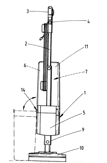
The electric vacuum cleaner shown is designed as a hand-
held apparatus. It has a housing 1 with a rod 2 at the top
which has a handle 3 at its end. An on/off switch 4 is
provided in the transition region between handle 3 and rod 2.
The connection of the electric cord is not shown.
The housing l i9 divided into a motor housing 5 and a
chamber 6 above it to receive a filter bag 7. The motor fan
has also not been shown in deta~il in the drawing.
The side of the filter bag 7 facing the motor housing S
is in communication via a socket V with the fan air duct 8.
The motor housing 5 passes on its bottom into a tube
coupling 9 which establishes the air flow connection to a
suction nozzle lO.
The suction nozzle lO can be a so-called suction-brush
nozzle which has a brush roller in the mouth of the nozzle,
the brush roller being placed in rotation by a separate
drive.
The fan motor therefore operates in upward direction and
consequently forces the dust-laden air into the filter bag 7
arranged upside down above the motor housing 5.
The entire cross-section of the housing l is a long
1 326333
rectangle with slightly bulging broad sides and similar
narrow sides. Figure 1 shows the vacuum cleaner, seen from
its broad side.
The chamber 6, which receives the filter bag 7 of
corresponding cross-section is formed by a textile bag 11
which is stiffened by a wire basket and which passes on the
bottom, i.e. on the side of the motor housing, into a
stiffened edge in the form of a chamber socket 12. The
stiffened textile bag 11 can be attached to this chamber
socket 12 by means of releasabIe clip-plug connection. The
plug-on region is stepped-down for this purpose. The step
can be noted from Fig. 1. It permits a well-defined inner or
outer attachment of the textile bag. An inner plug
attachment is preferred.
For the removal of the filter bag 7, the housing 1 can
be swung open with practically total freeing of its cross-
section. The swung-open position can be noted from Fig. 1
(shown there in dash-dot line) and from Figs. 5 and 7. The
swing shaft 14 which makes this possible is located on one
narrow side of the housing 1. Its bearing lugs on the
chamber-socket side bear the reference number 15. These
bearing lugs are located in the transition region between the
narrow side and the broad side of the chamber 6. A
continuous bearing lug of the motor housing 5 extends between
the two bearing lugs 15.
In the region of the parting joint between motor housing
S and chamber 6 there is furthermore integrated an
intermediate support T on which the filter bag 7 is seated.
The filter bag intermediate support T has a cross-section
which is adapted to the cross-section of the housing but is
set back from the wall of the housing so that in the coaxial
position of motor housing S and chamber 6 shown in Fig. 1 it
1 326333
.
is substantially completely blocked from view. Except for a
small place for access, it is namely gripped by the
projecting lower edge of the chamber socket 12 of the filter
bag intermediate support T which is also attached in
swingable manner, and swings around the same swing shaft 14
as the filter-bag chamber 6. On the hinge side, the
intermediate support T therefore also forms, in the same
manner as the chamber socket 12, two bearing lugs provided
here with the reference number 16.
The filter bag 7 which directly adjoins the intermediate
support T has a bottom 17. Its general contour also
corresponds to the cross-sectional shape of the chamber
socket 12 which for the supporting application in the region
of the narrow sides of the bottom 17 forms one edge step 18
each on the inner wall. As a result of this, the bottom 17
cannot slide into the chamber;6 in the swung-open position of
the apparatus. The bridge-like application of the bottom 17,
on the other hand, results in a certain ability of the bottom
to bend in the central region. The common swing shaft 14 of
the chamber socket 12 and the filter-bag intermediate support
T extends approximately at the level of the supporting edge
step 18 of the filter-bag bottom 17. In the closed housing
~Fig. 2), the edge step grips over the top side of said
bottom 17 so that it is not pushed off in upward direction
upon the suction blowing. As already indicated, the lower
side of the bottom 17 rests on the top side of the filter-bag
intermediate support T. There results in this connection, in
the regions of the narrow side of the bottom 17, a sort of
clamping-jaw fastening between the chamber socket 12 and
intermediate support T.
In this position, with the stepped-down, cylindrical
mouth end 8' of the blower air duct 8 extends into the lower
~ 326333
region of a socket 19. The latter protrudes above the top
side of the filter-bag intermediate support T. The socket 19
is formed from the very start on the intermediate support T
and, passing through an opening 20 of corresponding cross-
section in the filter-bag bottom 17, extends into the inside
of the filter bag 7, sealing the edge.
In order to prevent sucked-in material falling back into
the region of the motor housing 5 in view of the upside down
position shown, the socket 19 is provided at its free end
with a valve flap 21. The latter freely rests with the
predominate part of its edge region on the end of the socket
19. It is fixed in position merely at the place designated
22, so that it lifts off under the action of ~he flow of air
but returns into its closed position upon a reduction in the
corresponding load on the bottom side. The valve flap 21 can
be made as a separate part and be associated with the place
22 by means of a clip attachment; as an alternative there is
of course the possibility of forming it thereon in the case
of correspondingly flexible material of the socket 19 of the
filter-bag intermediate support T.
The socket 19 tapers toward its free end so that its
introduction into the opening 20 has practically a centering
effect.
As can further be noted from Fig. 2, the end edge is
beveled. It extends downward in the direction of the swing
shaft 14. A theoretical line extended in this direction
intersects the swing shaEt. The connection point 22 is
located in the higher region of the end edge of the socket.
The socket 19 furthermore has advisedly a radial
curvature with respect to the shaft 14. The intermediate
support T has window-like openings between the base region of
the socket 19 and the region on the side of the swing shaEt.
1 326333
The arm of the frame on the hinge side has, in this
connection, a larger width than the two arms of the frame
facing the broad sidewall of the housing.
On its free end, the intermediate support T forms at its
end there a freely accessible handle 24. It is an angular
extension on the bottom side. This extension comes from a
region which is set back with respect to the end side 25
there. The corresponding leg extends vertically. The
adjoining, substantially horizontal leg extends back to the
outer wall of the housing and terminates in the same plane as
the latter. In the region of the handle there is a hook
detent device tnot shown in detail) which can be actuated by
a push button and secures the closed condition of the
housing. The corresponding area of the motor housing 5 has a
niche-like recess to receive the handle 24. The recess bears
the reference number 26.
Upward-directed projections 27 extend also from the top
side ~in the position shown in Fig. 4) in the region of the
longer frame arms of the intermediate support. The
projections close grip openings 28 on the longer side edges
of the filter-bag bottom 17. Both grip openings 28 are
beveled and open toward the corresponding inner wall of the
chamber socket. In the open position of the housing 1, the
filter bag can be conveniently grasped by a clamping grip
around the central zone of the bottom 17 of the filter bag,
which zone has been constricted in the manner of a wasp's
waist, and then be lifted out of the chamber 6. The filter-
bag intermediate support T is furthermore so associated and
developed in this connection that it moves through a limited
angle of swing, i.e. it cannot pass into the 180 angle
position of the chamber socket 12; rather it remains in the
position which lies approximately in or beyond the vertical
1 326333
position E-E of the cross-sectional plane of the socket
connection, so that the socket connection V is already beyond
the bisector of the maximum region of swing of 180. In this
position, there is sufficient free space for the filter bag 7
in order to pull it off from the intermediate support. The
transfer into the position opposite the upside-down position,
i.e. with the opening 20 pointing upward, takes place without
it being possible for dust or larger particles to escape~
The filter bag can therefore be grasped conveniently and
lifted out in the above-described manner or after removal of
the chamber. The wall of the bag is not pushed in. Its wall
need not be touched upon its removal; any blowing out is
eliminated. By stretching the bag a suction effect can at
most be produced. The insertion of a new filter bag is
possible in very simple manner in the same way, since the
chamber is open toward the top over its entire cross-section
(see Fig. 1). It is therefore merely necessary now to swing
the chamber 6 back into the position shown in solid line in
Fig. 1, in which position the upper structure of the housing
1 comprising the chamber 6 is automatically locked on the
motor housing 5. Upon this swinging-back movement, the
opening 20 entraps the socket 19, or vice versa. This can
take place in the vertical position of the filter-bag
intermediate support T which is possibly still present by
frictional engagement or else only when the intermediate
support rests with its back again on the top side of the
motor housing S. In the closed position, the projections 27
again fill the grip openings 28 practically completely, i.e.
to such an extent that no outward bulges in the non-woven
type paper filter wall 31 can occur upon the inflating of the
filter bag or else due to the weight of the filling.
In order to enlarge the grip openings 28 which lie
_g_
1 326333
opposite each other, the wall region 12' of the inner wall of
the chamber socket 12, which lies in this direction and
therefore points outward, is hollowed out somewhat.
For a foolproof attachment of the filter bag 7 in proper
position, the bottom 17 of the latter has, in the region of
the two narrow sides, orientation features 32 which engage in
mating features 33 in the region of the inner wall of the
chamber socket 12. The orientation features consist of
trapezoidal projections on the narrow side of the plate-
shaped body forming the bottom 17. In this way there is
obtained a properly aligned positioning of opening 20 and the
socket 19 before an improper attachment is noticed by a
coming together of the housing parts which does not permit
closure. The facing longitudinal sides 27' of the
projections 27 are rounded transversely, which also serves
properly to position the bottom 17. They act as guide
surfaces on the corresponding rounded base of the recess of
the grip openings 28. Tongues 31a, 32b and 32c are provided
in addition at symmetrical angles to the opening 20. The
side-edge tongues 32b and 32c extend obliquely into the grip
openings. They are covered on their top side with a foam
material Sch which forms a sealing-ring zone of the hole 20.
The fold edges K of the wall (paper) of the filter bag held
against the bottom side of the bottom 17 intersect the grip
openings, and the tongues 32b and 32c extend over them.
The chamber or chamber socket 12 can be disengaged from
the swing shaft 14. In this way, it is possible to carry the
chamber containing the full filter bag 7 conveniently to the
garbage pail or the like. Furthermore, the chamber 6 and the
textile bag 11 stiffened by a wire basket can be easily
cleaned from time to time without the entire apparatus being
attached to them.
--10--
1 326333
The connection point on the chamber-socket side is a
housing-like projection 12' formed thereon and extending into
the region of the shaft 14, the projection extending
practically in coincidence with the bearing lugs 15 fastened
on the housing and the journal-pin bearing lugs 16 of the
filter-bag intermediate support T. The detent means are
formed by pins 50 which are under spring action with respect
to each other and in outward direction. The pins extend
beyond the end surface of the projection 12'. This
protruding section is developed as a beveled trap head 51.
The trap bevel bears the reference number 52. The trap heads
51 have a flattened cross-section and cooperate with the
journal-pin bearing lugs 16 of the intermediate support T
which lie in front of them. Each of these bearing lugs 16
forms an outwardly open radial slot 53. The radial slot 53
widens outward in funnel shape. The funnel shape favors a
centering on the shaft centerline but it also forms a run-on
flank 54 which corresponds to the angle of inclination of the
trap bevel 52. The inverse end of the run-on flank 54 then
continues into a blocking shoulder 55 transverse thereto, the
back of the trap bevel engaging under the shoulder in locking
manner The blocking shoulder 55 is the partial wall region
of a receiving recess 56 for the trap head 51 of the journal-
pin bearing lugs 16. The narrowest width of the radial slot
53 corresponds to the flattened width of the trap heads Sl.
The disengagement is only possible in the swung-down
position o the chamber socket 12 and with the support T
swung against the housing since the trap heads are then in
the ready-for-disengagement position, as shown in Fig 12. To
be sure, in this position a fur~her slight swinging of the
chamber socket must be effected, since a partial region of
the top of the trap head 51 is still in slight blocking
1 326333
engagement with respect to the receiving recess 56. Once the
proper position for disengagement has been assumed, the
chamber socket need only be lifted upward. The trap bevel 52
which points upward in this position then runs over the
blocking shoulder 55. For the engagement, the run-on flank
54 of the radial slot 53 proves useful. It guides the trap
heads back against the force of the compression spring 57
acting on the pins 55.
The compression spring 57 is a helical compression
spring.
The pins 50 are secured against rotation. For this
purpose they are provided with longitudinal ribs 58 which
engage in longitudinal grooves 59 of corresponding contour in
the recesses of the projections 12'. The inward directed
ends of the pins 50 have stops so that the pins 50 do not
jump out of their housing despite the spring pressure.
In all other possible angular positions, the trap heads
51 assume a blocking position relative to the corresponding
journal-pin bearing lugs 16.
A different development of the swing-limiting stop for
the intermediate support T can be noted from Figs. 10 to 12,
to the extent that the journal-pin bearing lugs 16 come
against a shoulder 61 on the housing side by a radial stop
projection 60.
The shaft 14 proper i3 formed by stub shafts 14' of the
journal-pin bearing lugs 16, the stubs being formed in the
back of the receiving recess 56 for the trap head 51. They
extend into corresponding cavities in the bearing lugs 15 of
the housing.
The receiving recess 56 is enlarged in the manner of a
slot in the direction of the plane of extension of the
intermediate support T.
-12-
1 326333
A further feature of the intermediate support T
consists, in accordance with the version starting from Fig.
17, in providing the intermediate support T with an extrusion
U. This extrusion consists of somewhat softer material than
the intermediate support T. The extrusion extends at least
on the edge side, so that not only is the narrow end edge of
the plate-shaped intermediate support T covered but also the
top and bottom sides of the intermediate support. The
flexible material provides in this way an edge seal not only
between the bottom 17 of the filter bag 7 but also with
respect to the cover of the motor housing 5. Furthermore,
the material of the extrusion U is also extended into the
region of the socket 19 of the intermediate support T,
surrounding this socket 19 in jacket-like manner. The
corre~ponding change in the sides toward the top side of the
intermediate support is provided by an edge perforation in
the region of the base of the socket 19. The perforations
are designated 63 and can be noted from Fig. 22. In the
region of the base of the ~ocket 19, facing the blower air
duct 8 located there, the extrusion forms a sealing lip 64
which extends into the stepped-down blower air duct. The
sealing lip 64 tapers in ~unnel-shape on the duct side.
The extrusion furthermore forms the above-described
projections 27 which extend into the grip openings 28 of the
bottom 17 of the filter bag. The relatively soft material
has at the same time sufficient flexibility so that no forced
coupling occurs. The projections 27 are formed of upwardly
bent off wall sections of the extrusion material ~rubber or
plastic), which wall sections have a curvature extending in
longitudinal direction or else terminate only at their ends
in curved sections, so that the desired standing ability is
present despite the softness.
-13-
1 326333
In order to increase the seal, the edge of the chamber
socket 12 on the filter-bottom side is pointed in the manner
of a cutting edge tsee Fig 4).
Furthermore the filter-bag bottom 17 is gripped over by
at least two projections 65 located on both side~ of the
opening 20 in the bottom 17. As can be noted from Fig. 15,
the gripping width is rather small, so that the filter bag
can be lifted out by a deliberate pull on the bottom 17.
Zones free of extrusion are only taken into account in
the region of the emergence of the journal-pin bearing lugs
16 and in the region of the handle 25.
The orifice edge of the opening 20 of the bottom 17 is
lined with an elastic layer 66 on the support side. This
layer extends around the opening 20 up to the periphery of
the bottom. It may be a foam material.
The extrusion U is utilized to form the valve flap 21.
It is a cover which extends over the mouth of the socket and
which is cut all around except at the hinge place 22.
The reference numbers have otherwise been applied by
analogy, without repeating the description.
All new features mentioned in the specification and
shown ln the drawing are essential to the invention even if
they have not been especially set forth in the Claims.
-14-