Note: Descriptions are shown in the official language in which they were submitted.
132~9
Ul.TRA-HIGH SPEED TWO-DI~:ENSIONAI. COORDINAI* TRANS~M PI~OCESSOR
1 BACKGROUNV OF l~lE INVENT~()N
1. Technical Field
This invention relates to information processors, and more
particularly to high speed coordinate transform processors
utilizing associative coupling between adjacent conductive layers.
2. Discussion
Coordina*e systems are schemes for locating points in a given
space by means of nu~erical quantities specified with respect to
some frame of reference. Common coordinate systems include the
Cartesian coordinate system, the Polar coordinate system, the
Spherical coordinate system and the Cylindrical coordinate system.
IDformation in one coordinate system may be transformed to another
~15 coordinate system by means of a system of equations which express
each point in one coordinate system as some function of the point
in the other coordinate system~ Such transfo~mations, for
example, frcm cartesian coordinates *o polar coordinates, are
required in a number of applications.
Prior approaches to performing rapid cnordinate
transformations have typically involved solving the transformation
equations in software on general purpose computers. A drawback to
- ,
~ 3 2 ~
-- 2 --
1 software approaches is that they are not fast enough for some
real-time or near real--time problems~ This is because of the time
required to sol~e the transformation equations. An alternative to
software approaches is to use a hard-wired implernentation o~ the
CO~DIC algorithm to perform coordinate transformations. This
provides an improvement in sp~ed over software solutions but still
requires on the order o~ microseconds to perfo~n a coordina-te
transform. Further, the hardwired CORDIC algorithm approach is
limited to trigonometric and transcendental transforms.
Consequently, it cannot perform extremely fast linear and/or
non-linear bi-directional transformation of two-dimensional
coordinate vectors. Other approaches, such as those used in
digital scan convertors, use a signi~icant num~er O:e active RAM
components in a memory loolsup table technique for coordinate
conversion. These devices have the drawback of being relatively
expensive and bulky because of the large number of RAM componen-ts
required. Also, such systems still do not achieve a~equate speeds
for some applications.
Accordingly, ik would be desirable to provide a processor
capable of performing coordinate transformations at higher speeds
than currently available processors. It is also desirab]e to
provide a processor that avoids the necessity of solving
transformation equations in performing coordinate transforms, to
thereby achieve faster processing speeds. It would also be
desirable to provide a coordinate transform processor that is
inexpensive and compact so that its processing capabilities can be
replicated a number of times in a relatively small space for
relatively little cost.
SUM&~RY OF THE INVENTION
Pursuant to the present invention, a coordinate transform
processor is provided that can rapidly solve coordinate
transformations. The invention consists of a multi-layer
substrate each layer having geometric patterns that conduct
signals. The geometric patterns are an analogue of the coordinate
..
i~2~ 9
- 3 -
systems being transformed. The transforlnation o~ an inpnt vector
to an output vector is per~ormed by interactive coupling among the
su~trate layers as a function o~ the geometric pattern on
adjacent layers.
In particular a first set o~ layers tlaving a geo~ ric
pattern corresponding to coordinate lines in a first coordinate
system is positioned between successive layers in a second set
having geometric patterns corresponding to coordinate lines in a
second coordinate system. A signal is then a~plied to the lines
in the first set of layers which intersect at a point that
represents a point in the first coordinate system. lhis signal is
coupled to adjacent layers in the second set. l`he couple~ signal
is then sensed and the intersecting l~int in the second set o~
layers that is nearest the point where the signal was introduced
in the first set o~ layers is determined. rhis determination may
be made by c~nparing the induced signal strength at intersectin~
points in the second set of layers and choosing the intersecting
point having the strongest induced signal. The chosen point in
the second set o~ layer~ represents the point in tl~e second
coordinate system that is the transformation o~ the equivalent
point in the first coordinate system. The above process may be
reversed to transform a point in the second coordinate system into
a point in the ~irst coordinate system. The resulting coordinate
transfonm processor perfonms extremely ~ast transfo~lations is
inexpensive to produce and may be replicated n-times to mllltil)ly
the capability n-fold.
Other aspects of this invention are as follows:
In a processor ~or per~o~ming coordin~te
trans~ormations the improvement comprising:
a first set o~ layers o~ p]anar members each having
signal conducting lines representing cocrdinate lines in a ~irst
coordinate system;
a second set of layers of planar members each having
signal conducting lines representing coordinate lines in a second
coordinate system;
. i, ;,.,~,.
~326~v~
- 3a -
layers in said first set being positioned adjacent to
said layers in the second set so that each layer in said first set
is positioned ~etween successive layer~ in said second set;
means for applying a signal to selected ones of said
signal conducting lines in said first set of layers, said selected
lines intersecting at a point that represents a point in said
first coordinate system;
means ~or detecting a signal in lines in said second set
of }ayers, said signal being induced by said signal applied at
said first intersection in said ~irst set of layers; and
means for comparing said detected signal at various
intersecting poin~s in said second set o~ layers, wherein the
intersecting point that is nearest said ~irst interseoting point
in said first set o~ Iayers can be determined by the strengt~J o~
the detected signal. t
A processor ~or per~orming coordinate transformations
comprising;
a ~irst set of layers of planar members each having signal
conducting lines representing coordinate lines in a first
coordinate system;
a second set of Iayers of planar members each having signal
conducting lines representing coordinate lines in a second
coordinate system;
layers in said ~irst set being positioned adjacent to said
layers in the second set so that each layer in said ~irst set is
positioned between successive layers in æaid second set;
means for applying a signal to selected ones of said signal
conducting lines in said ~irst set o~ layers, said selected lines
intersecting at a point that represents a point in said ~irst
coordinate s~stem;
means for detecting a signal in lines in said second set of
layers, said signal being induced by said signal applied at said
first intersection in said ~irst set o~ layers; and
means for comparing said detected signal at various
intersecting points in said second set o~ layers, wherein the
intersecting point that is nearest said first intersectin~ point
in said first set of layers can be determined by the strength o~
the detected signal.
.. .. .. .
~L~2~t~5~
- 3b -
A method for tr~sfcrming data from one coordinate
system tv another, said method comprising:
positioning layers of planar members so that a first set of
layers o~ planar members are adjacent to layers in a second set of
planar n~olbers and each layer of said first set is positioned
between s wcessive layers fran the second set, said first set of
layers having signal condu¢ting lines representing coordinate
lines in a first coordinate system and said second set oi layers
havi.ng signal conductive lines representing coordinate lines in a
second coordinate system;
applying a signal to selecte~ lines in said first set of
layers, said selected lines intersecting at a point that
represents a point in said first coordinate system;
detecting a signal in said conductive lines in said second
set of layers, said signal being induced by said signal applied to
said adjacent conductive lines in said first set of layers; and
comparing said detected signal at various intersecting points
in said second set of layers wherein the intersecting point that
is nearest said first intersecting point in said first coordinate
system can be dete~nined by the strength o~ the detected signal.
BRIEF DESCRIPTION OF TH~ DRAWINGS
The various advantages o~ the present invention will become
apparent to one skilled in t~le art ~y reading the followin~
speci~ication and by reference to the following drawiogs in which:
FIG~ 1 is a diagrammatic description of the c(~rdinate
trans~orm problem and tbe concept o~ the present i.n wr~ti.on ~br t:tle
(R, ~) to tx. Y) case.
~a
. I'i ~
~ ,, 1 .
,
- .
:: `
1326.~59
-- 4 --
FIC. 2 is a description of the coordinate trans:Eorm prob]em
and the concept of the present invention for the ar~itrary
transform case.
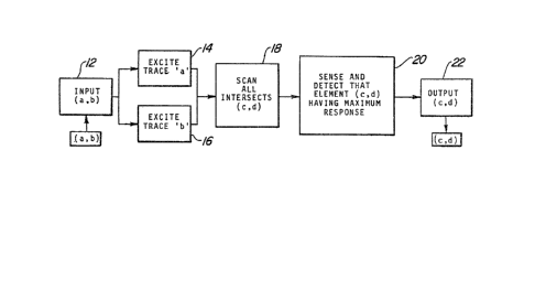
FIG. 3 is a flowchart showing the processing of a coor~inate
transform processor in accordance with the present invention.
FIG. 4 is a diagram of the various substrate layers showing
the conductive lines in accordance with the present invention.
FIG. 5 is a drawing of condllctive pads in the prei!erred
embodiment of the present invention.
FIG. 6 is a drawing of a board layout o~ a coordi~ate
transform processor in accordance with the present invention.
DESCRIPq'ION OF THE PRI~ U~) EME~U)I~EN'I'S
~ eferring to FIG. l, a descrip-tion of the coordinate
transform problem is sbown for the case of transformation be-tween
polar and cartesian coordinates. In particulaI, ~IG. 1 shows a
point (R,~ ) in a two-dimensional space A X B represented by polar
coordinates. A is the maximum distance in the Y direction and B
is the rnaximurn in the X direction. R represents the range or
distance from the lower ~e~t most point. ~ represents the angle
from a starting reference point on a 360 circ]e. The problem is
to find the point (x,y~ in cartesian coordinates that corresponds
to the point (~, ~). Alternatively, a given point (x,y) shown in
a two-dimensional space A X B represented by cartesian
coordinates, ma~ be transforme~ to a point on l~olar coorc~inates
(1~
One way of viewing the problem is to superimpose the polar
coordinates on top of the cartesian coordinates in a coordina1e
transforrn processor lO) as shown in the right side of ~(1. l. The
resulting space A X B represents the entire space of the resulting
superimposed coordinates, and is equal to the s~ace A X l3 covered
by the polar and cartesian coordinates. To perform coordjnate
trarlsformations without using transformation equations, the
concept, in accordance with the present invention, is t;o excite a
: .. ; . ~; - ~ .
,
~ 326~5s~
-- 5 --
1 point (R,~ ) and to detect the signal induced at the nearest
superimposed (x>y). That (x~y) will then represent the transform
o~ the (R,~ ) point. Alternatively, a point (x,y) may be excited
and the induced signal at the nearest (R,~ ) will be the transform
of the (x,y) point.
Similarly, FIGo 2~ shows the tran~orm problem ~or the case
of an arbitrary space. In particular, a given point (a,b) is
shown in space A X B in a first coordinate system. It is desired
to find the corresponding point (c,d) in a second coordinate
system representing the same space A X B. Alternatively, given
point (c,d) in a second coordinate system, the problem is to find
the corresponding point (a,h) in the first coordinate system. As
shown in FIG~ 2~ the first and second arbitrary coordinate systems
can be superimposed on each other in the same A X B space in the
coordinate trans~orm processor 10. A signal exciting a point on
the first coordinate system wi]l induce a signal in the second
system. This induced signal will be strongest at the point which
represents the transformation of the excited point in the first
coordinate system.
Re~erring now to FIG. 3, there is shown a flowchart ~or the
control/processing algorithm in accordance with the preferred
embodiment of the present invention. This algorithm accomplishes
the trans~ormation of a point (a,b) on a first coordinate system
into point (c,d) on a second coordinate system. Initially, the
coordinate transform processor 10 accepts as input the coordinates
~a,b). This input may be, for example, a digita] representation
(to any arbitrary accuracy) of coordinates (a,b). (Step 12) The
line in the first coordinate system representing "a" is then
excited. (Step 14) This line may be a conductive trace, and the
excitation may be by means of an applied electrical signal, as
will be explained in more detail belowO At approximately the same
time, the "b" line is also excited. (Step 16) Next~ a sensor
scans all (c,d) intersects in the second coorc]inate system. (Step
18) This may be donc, ~or example, by measuring voltage or
current in each (c,d) trace either serially or in parallel. The
.
~32~59
1 (c,d) intersect having the maximum response is then i~entified.
(Step 20) This identification may be accomplished by u~ing a
sensor threshold. MoreoverJ tne thresho]d may be adaptive to
further increase the speed of the coordinate trans~orm processor
1~. 'rhis maximum (c,d) intersect is then provided as output ~rom
the coordinate transforrn processor 10. (S-tep 2~) This output n~ay
be, for example, a digital representation (to arbitrary accuracy)
of coordinates (c,d).
I-t is important to note that resolution to any desired degree
1~ of accuracy may be obtained by re-processing a given in~ut
coordinate having a known resolution, in successively sma]~er
scales. In this way, a smaller and smaller space will be covered
with each re~etition. Thus, the accuracy of the output is only
limited by the accuracy of the input.
In FIG. 4 there i8 shown a substrate layout fOI' a first
embodiment oY the coordinate transform processor ~0 in accordance
with the present invention. The coordinate transform processor 10
is composed~ of ten layers. ~ach layer has signal conductin~
patches that follow a prescribed geometric pattern. ~`hese
2~ conducting patches may comprise copper conductors on a printed
circuit substrate. In layers one, five and seven, are the X
lines, and in layers three and nine are the Y lines o~ the X-Y
coordinate system. In layers two and eight are the ~ lines7 and
in layers four, six and ten are the ~ lines in the R-~ coordinate
system. Each layer is arbitrari]y thin and is separated from al]
adjacent layers by an arbitrarily thin dielectric. It is
preferred that at least one layer of each type of trace in one
coordinate system be sandwiched between two differellt types of
layers in the other coordinate system. Layers of the saMe pat-tern
~o are repeated in order to insure maximum coupling among all the
traces. It may be desirable to cover the coordinate tranS~oJm
processor 10 above and/or below by a ground plane to shield the
processor IQ from unwanted e]ectromagnetic interference.
In ~'IG. 5 there is shown a second embndimellt o~` the
coordinate transform processor 10 in acc:ordance with the present
., ,: . ~
~ 3~5~
- 7 - :
l invention. The second embodiment (~iffers from the first by the
use of conductive pads 24 at each (x,y) intersection and at each
(r, ~ ) intersection a]ong each trace line. Thus, in this
embodiment, it is the array of conductive patches which fo]lows
the prescribed geometric patterns shown in FTG. 4 rat;her than
continuous conductive lines. The first embodiment is less
expensive because the separate conductive pads ~4 are ~ot used,
but nlay require more sensitive sensor circuitry. In the second
embodiment the conductive pads 24 provide improved coupling
between layers. It should be noted that in the left side of FIG.
5 only the (x,y) geometric pattern of c~nductive pads 24 i.s shown.
Conductive pads 24 for the (r, ~ ) lines are not shown. In
addition, each conductive pad 2~ is independently accessible
through independent access lines 2~. On the right side of FIG. 6
the ten layers of the coordinate transform processor 10 are shown.
l`he access lines 26 connecting each conducti.ve pad 24 are also
shown. However, the bundle of indivi.dual access lines ~hown on
the left of FIG. 5 are represented by single lines 26 on the right
o~ FIG. 5. Additional layers which may be required for access
li.nes are also not shown.
In FIG. 6 the functiona]. descri.ption of the total boarcl
layout o~ the coordinate transform processor ~0 is shown. X-Y
drivers/sensors 28 are connected to the traces in the X-Y layers
in the first embodiment or to each indi.vi.dual conducti.ve pad 24 in
the second embodiment, through access lines 2~. Simi.lar]y R-3
drivers/sensors 30 are connected to the traces or to the
conductive pads 24 i.n the (r-~) layers through access lines 26.
~oth the drivers/sensors 28, 30 perform the functi.on of exciting
the traces. This step is shown as æteps 14 and 16 i.n FI~. ~. The
~riverslsensors 28, 30 also perfoI~n the flmction of scanning an(l
detec-ting the intersect with the maxim~n resl~onse as descril)e(l in
steps 18 and 20 in FIG. 3.
0verall, the processing performed by the coor(linate trans:forM
processor 10 is as follows. The initial illpUt indicatin~ the
poi.nt (a,b~ in the first coordinate system is fed to the
,
.
~326~ ~
1 coordinate transform processor ~0 by a host processor (not shown)
to an interface circuit 32, shown in FIG. ~. This information
(a,b) is then ~ed from the interface circuit 32 to a control
circuit 34. The control circuit 34 directs the (a,b) signal to
the appropriate driver/sensor, which may be the X-Y driver/sensor
28 or the ~-~ driver/sensor 30. The driver/sensor then excites
the traces, or pads 24, corresponding to the point (a,b).
The above processing may be accomplishe~ in a number of ways
using a combination of the control circuit 34 and the
1() drivers/sensors 28, 30. For example, the processing may be in the
amplitude domain where single pulses are appropriately timed and
sensed via threshold levels to direct a signal to the appropriate
trace. Alternatively, the processing may be in the frequency
domain where signals of appropriate frequency content are used and
localized combinations sensed using the appropriate filters. Once
the (a,b) traces are excited by1 for example, the X-Y
drivers/sensors 28, the R-~ drivers/sensors 30 will scan and
sense the (r,~ ~ intersection having the maximwm response. This
response will be caused by coupling of the signal from the (x,y)
intersection to the nearest (r,~ ) intersection. For examp}e, in
the preferred embodiments, where there are electrical signals
passing through the traces, there may be capacitive coupling
between the adjacent layers. It should be noted, however, that
other means of coupling are possible such as magneti(: or optica~
coupling between successive layers. For example, in an optical
embodiment, sone or all of the functions of the coordinate
transform processor 10 may be implemented with optical components.
Whatever the mode of coupling, it is an important characteristic
of the coupling that the speed of coupling be fast, and the
coupling strength decrease with the distance away fron the excited
intersection (a,b). In this way, one intersection (c,d), that is
closest to (a,b) will have a stronger induced signal than any
other (c,d) point.
:,
'
,,
1 3 2 ~
1The signal induced in the (r, ~) intersection will then be
detected by the R- ~ driver/sensor 30. As described above, this
sensing may be in either the amplitude or the :erequency domain.
It should be noted that the support circuits, specifically the
5drivers/sensors 28, 30, the control circuit 34, and the interface
circuit 32, need not reside on the same circuit board as the ten
layers containing the traces.
It will be appreciated that the coordinate trans~orm
processor 10 described above is inexpensive to produce using
conventional printed circuit board technology. Also, it requires
only simple support circuitry. Moreover, it performs coordinate
transformations at extremely fast speeds. In the amplitude
processing domain, for example, one nanosecond pulses may be used
to perform one billion ~X,Y)-to-(R, ~ ) or (R, ~ )-to-(X,Y)
coordinate transformations per second. This is at least three
orders of magnitude faster than availa~le coordinate
transformation processors known to the inventor. Even higher
speeds are obtainable, limited only by support circuitry and
millimeter wave effects in the multi-layer printed circuit
substrate itself. Resolution of the coordinates is arbitrarily
fine and is limited only by the printed circuit substrate or
equivalent manu~acturing technology. Those skilled in the art can
appreciate that other advantages can be obtained fron -the use of
this invention and that modi~icaticns can be made without
departing fron the true spirit of the invention a~ter studying the
specifications, drawings, and following claims.
. .
: